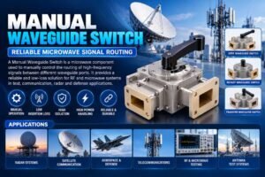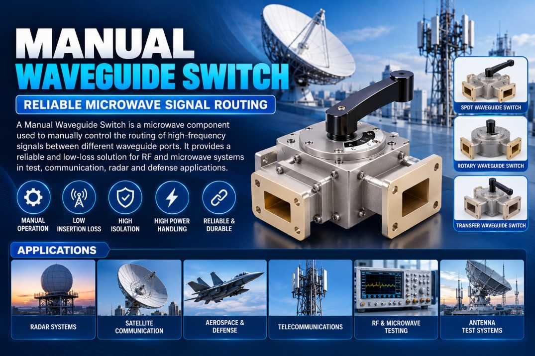
A Manual Waveguide Switch is a microwave component used to manually control the routing of high-frequency electromagnetic signals between different waveguide ports. It allows an operator to physically select one signal path from multiple available paths without requiring an electrical control circuit or automated actuator.
Manual waveguide switches are widely used in microwave laboratories, radar systems, satellite communication equipment, RF testing, telecommunications, and defense electronics. They are particularly useful when reliable and repeatable signal-path selection is required without the complexity of motorized or electronically controlled switching systems.
What Is a Manual Waveguide Switch?
A Manual Waveguide Switch is a passive microwave switching device designed to direct an RF or microwave signal from one waveguide port to another. The switching operation is performed manually using a mechanical handle, knob, lever, or rotary mechanism.
Unlike an electronic RF switch, a manual waveguide switch does not normally require electrical power for changing the signal path. The operator physically changes the internal mechanism to connect the desired waveguide route.
Waveguides are hollow metallic transmission structures that guide electromagnetic energy, particularly at microwave and millimeter-wave frequencies. Because waveguide systems can provide low transmission loss and high power-handling capability, manual waveguide switches are useful in applications where signal integrity and mechanical reliability are important.
How Does a Manual Waveguide Switch Work?
The working principle of a Manual Waveguide Switch is based on mechanically changing the connection between waveguide ports.
A typical switch consists of multiple waveguide ports, a switching mechanism, a movable internal section, and a mechanical actuator. When the operator moves the handle or rotary control, the internal waveguide section changes position.
In one position, the internal path connects one input port to a selected output port. Moving the mechanism to another position changes the electromagnetic path and connects the signal to a different port.
The switch therefore provides controlled RF signal routing without requiring an electronic switching circuit.
The basic operation can be described as:
Input Waveguide → Mechanical Switching Mechanism → Selected Waveguide Path → Output Waveguide
The internal geometry is carefully designed so that the electromagnetic field can transition between the selected ports while maintaining acceptable insertion loss, return loss, and isolation.
Construction of Manual Waveguide Switch
A Manual Waveguide Switch generally includes several important components.
Waveguide Ports
The ports provide interfaces for connecting the switch to waveguide transmission lines, antennas, filters, amplifiers, test equipment, or other microwave components.
Switching Mechanism
The switching mechanism physically changes the RF path. Depending on the design, this may involve a rotary or sliding structure.
Mechanical Actuator
A handle, lever, knob, or rotary control allows the operator to select the desired signal path.
Waveguide Body
The main body provides the electromagnetic transmission path and mechanical structure. It is typically manufactured from conductive materials suitable for microwave applications.
Position Indicator
Many manual switches include a visual indication of the selected position. This helps operators identify the active RF path during testing or system operation.
Mounting Structure
Mounting provisions allow the switch to be securely integrated into microwave equipment, test racks, panels, or RF assemblies.
Key Features of Manual Waveguide Switch
Important features can include:
- Manual mechanical operation
- Multiple waveguide port configurations
- High-frequency microwave operation
- No electrical power required for switching
- Low insertion loss
- High isolation between selected and unselected paths
- Reliable mechanical construction
- Repeatable switching positions
- High power-handling capability depending on design
- Compact microwave system integration
- Suitable for laboratory and field applications
- Long mechanical operating life when properly designed
Actual performance depends on the specific waveguide size, frequency band, construction, and manufacturer specifications.
Types of Manual Waveguide Switches
Manual Waveguide Switches can be classified according to their port configuration and switching arrangement.
SPDT Waveguide Switch
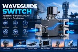
A Single Pole Double Throw configuration allows one input to be manually connected to either of two output paths.
This configuration is useful when an RF source needs to be routed between two different microwave components.
Transfer Waveguide Switch
A transfer switch can route signals between multiple waveguide ports according to its mechanical position. It can be useful in test and measurement systems where different signal paths need to be selected.
Rotary Waveguide Switch
A rotary configuration uses a rotating internal mechanism to change the RF path. Rotary designs can provide multiple selectable positions depending on the application.
Multi-Port Waveguide Switch
Multi-port switches provide several possible signal-routing configurations. They are useful in complex microwave test systems and RF distribution architectures.
Important Technical Specifications
When selecting a Manual Waveguide Switch, several specifications should be evaluated.
| Parameter | Importance |
|---|---|
| Frequency Range | Defines the supported microwave operating band |
| Waveguide Size | Determines physical and electromagnetic compatibility |
| Insertion Loss | Indicates signal loss through the selected path |
| Isolation | Indicates separation between selected and unselected ports |
| VSWR | Indicates impedance matching performance |
| Power Handling | Determines maximum RF power capability |
| Switching Configuration | Defines available signal paths |
| Mechanical Life | Indicates expected operating cycles |
| Operating Environment | Defines suitability for temperature and environmental conditions |
| Interface Type | Determines compatibility with the microwave system |
The actual values should always be verified from the manufacturer’s technical datasheet before system integration.
Why Is Insertion Loss Important?
Insertion loss is an important parameter in any microwave switching system. It represents the amount of RF power lost as the signal passes through the selected switching path.
Lower insertion loss is generally desirable because it helps preserve the available signal power.
In high-frequency systems, even relatively small losses can become important when multiple microwave components are connected in series. Therefore, the switch should be selected according to the frequency, power level, and total system loss budget.
Importance of Isolation
Isolation describes how effectively the switch separates the selected RF path from an unselected port.
High isolation is important when unwanted RF energy reaching another signal path could interfere with measurements or system operation.
For example, in a microwave test setup, an operator may need to switch between two antennas or two measurement paths. Adequate isolation helps reduce unwanted coupling between the unused and active paths.
Manual Waveguide Switch vs Electronic RF Switch
Manual and electronically controlled switches serve different requirements.
A Manual Waveguide Switch is operated mechanically and normally does not require electrical power to change position. This makes it useful for laboratory setups, configuration changes, maintenance operations, and systems where switching does not need to happen automatically.
Electronic or motorized switches can provide remote or automated switching but may require control electronics, power, and additional system integration.
The appropriate choice depends on whether the application requires manual operation, remote control, rapid switching, automation, or mechanical simplicity.
Applications of Manual Waveguide Switch
Manual Waveguide Switches are used in a wide range of microwave applications.
Radar Systems
Radar test and development systems can use manual waveguide switching to select between different RF paths, antennas, loads, or measurement equipment.
Satellite Communication
Microwave and satellite communication systems can use waveguide switches for signal-path selection and equipment configuration.
RF and Microwave Testing
Laboratories use manual switches to simplify the connection of multiple microwave components during testing and characterization.
Aerospace and Defense
Defense electronics often require reliable microwave signal routing between subsystems, test equipment, antennas, and RF components.
Telecommunications
Microwave communication systems can use waveguide switching for controlled routing between different RF paths.
Antenna Test Systems
A manual switch can allow operators to select different antennas or microwave measurement paths during antenna characterization.
Research and Development
Microwave laboratories benefit from manual switching because engineers can quickly change experimental configurations without modifying electronic control systems.
Advantages of Manual Waveguide Switch
The major advantages include mechanical simplicity, reliable operation, no requirement for electrical switching power, and straightforward integration into microwave test setups.
A manual switch can also provide clear physical feedback regarding the selected RF path. This can be particularly useful during laboratory testing and maintenance.
Because waveguide switches are designed specifically for microwave transmission, they can also provide suitable RF performance for applications where coaxial switching may not be appropriate.
How to Select a Manual Waveguide Switch
Before selecting a Manual Waveguide Switch, consider the following factors:
- Operating frequency: Ensure the switch supports the required frequency band.
- Waveguide size: Match the switch to the existing waveguide standard.
- Port configuration: Determine whether SPDT, transfer, rotary, or another configuration is required.
- Insertion loss: Check the maximum acceptable signal loss.
- Isolation: Select suitable isolation for the application.
- Power handling: Verify peak and continuous RF power requirements.
- Mechanical operation: Consider switching mechanism, position indication, and required operating cycles.
- Environmental conditions: Check temperature, humidity, vibration, and other requirements.
- Mounting: Verify dimensions and mounting provisions.
- System compatibility: Ensure the interfaces match the existing microwave components.
Maintenance of Manual Waveguide Switches
Proper maintenance can help maintain reliable operation. Operators should periodically inspect the mechanical actuator, mounting hardware, waveguide interfaces, and switching mechanism.
Waveguide flanges should be kept clean and properly aligned. Excessive mechanical force should be avoided when operating the switch. If the manufacturer specifies lubrication, inspection, or operating procedures, those instructions should be followed.
For precision microwave systems, RF performance can also be periodically tested to identify changes in insertion loss, isolation, or VSWR.
Conclusion
A Manual Waveguide Switch is a practical microwave component used to mechanically control RF signal routing between different waveguide paths. Its combination of mechanical operation, reliable signal routing, and microwave compatibility makes it valuable in radar, satellite communication, aerospace, defense, telecommunications, RF testing, and research applications.
When selecting a Manual Waveguide Switch, frequency range, waveguide size, insertion loss, isolation, power handling, port configuration, mechanical life, and environmental requirements should all be considered. Choosing the correct switch ensures that the microwave signal path remains compatible with the overall RF system.
FAQs About Manual Waveguide Switch
1. What is a Manual Waveguide Switch?
A Manual Waveguide Switch is a microwave component that allows an operator to mechanically select and route an RF signal between different waveguide paths.
2. Does a Manual Waveguide Switch require electrical power?
Normally, no. The switching operation is performed mechanically using a handle, lever, knob, or rotary mechanism.
3. Where are Manual Waveguide Switches used?
They are used in radar, satellite communication, aerospace, defense, telecommunications, microwave laboratories, antenna testing, and RF measurement systems.
4. What is insertion loss in a waveguide switch?
Insertion loss represents the RF power lost as the signal passes through the selected switching path.
5. Why is isolation important in a waveguide switch?
Isolation helps prevent unwanted RF energy from coupling into unselected ports or signal paths.
6. What frequency range can a Manual Waveguide Switch support?
The frequency range depends on the waveguide size and specific switch design. The manufacturer’s datasheet should be checked for the exact operating range.
7. What is an SPDT waveguide switch?
An SPDT, or Single Pole Double Throw, waveguide switch allows one input to be manually connected to either of two output paths.
8. Can Manual Waveguide Switches handle high RF power?
Some are designed for high-power microwave applications, but the actual power-handling capability depends on the specific design and frequency.
9. What is the difference between a manual and motorized waveguide switch?
A manual switch is operated directly by an operator, while a motorized switch uses an actuator and control system to change the RF path.
10. What should be checked before buying a Manual Waveguide Switch?
Check the frequency range, waveguide type, port configuration, insertion loss, isolation, VSWR, power handling, mechanical life, dimensions, and environmental specifications.