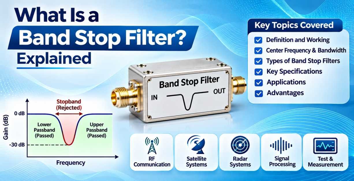
A band stop filter is an electronic filter designed to attenuate or reject signals within a specific frequency range while allowing frequencies below and above that range to pass through. It is also known as a band reject filter or band elimination filter. This type of filter plays an important role in electronic circuits, RF communication systems, microwave engineering, audio processing, and signal transmission applications.
In modern electronic and communication systems, unwanted frequency components can affect signal quality, cause interference, and reduce overall system performance. A band stop filter helps overcome these challenges by suppressing unwanted frequency bands without significantly affecting the frequencies outside the rejected range.
Band stop filters are widely used in wireless communication equipment, RF systems, radar technology, audio devices, instrumentation, and industrial electronics. They are particularly useful when a specific frequency range needs to be removed from a signal while preserving the remaining frequency components.
Understanding the working principle, frequency response, types, specifications, and applications of a band stop filter helps engineers select the right filtering solution for their electronic and RF systems.
This guide explains everything about band stop filters, including their operation, technical characteristics, advantages, and importance in modern RF and microwave engineering.
1. What Is a Band Stop Filter?
A band stop filter is an electronic circuit or RF component that blocks or significantly attenuates signals within a specified frequency range while allowing signals outside that range to pass.
In simple terms, a band stop filter removes unwanted frequencies from an electrical signal.
Unlike a low pass filter or high pass filter, which attenuates frequencies on one side of a cutoff point, a band stop filter rejects a selected range of frequencies between two frequency limits.
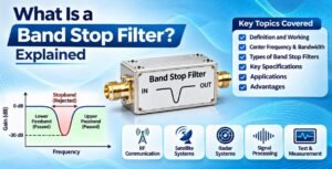
A band stop filter generally has three important frequency regions:
- Lower Passband: Frequencies below the lower cutoff frequency pass through the filter.
- Stopband: Frequencies between the lower and upper cutoff frequencies are attenuated.
- Upper Passband: Frequencies above the upper cutoff frequency pass through the filter.
For example, a band stop filter designed to reject frequencies between 900 MHz and 1 GHz will attenuate signals within that range while allowing frequencies below 900 MHz and above 1 GHz to pass, subject to its specified performance characteristics.
Band stop filters are especially useful in applications where unwanted interference occurs within a particular frequency band.
2. How Does a Band Stop Filter Work?
A band stop filter works by creating a frequency-dependent response that suppresses signals within a selected frequency range.
Its operation depends on the filter design and the electrical characteristics of the components or transmission-line structures used.
A basic band stop filter can be constructed using combinations of resistors, capacitors, and inductors. More advanced RF and microwave band stop filters use resonant structures and electromagnetic coupling techniques to achieve precise frequency rejection.
The working principle can be understood through three main stages.
2.1 Lower Frequency Passband
Signals with frequencies below the lower cutoff frequency pass through the filter with relatively low attenuation.
These frequencies are outside the rejection band and are generally unaffected by the filtering operation, apart from the filter’s normal insertion loss.
2.2 Stopband Frequency Range
When the input signal reaches the specified stopband, the filter begins to attenuate the signal.
The amount of attenuation depends on the filter design, resonant frequency, bandwidth, and stopband rejection specification.
The purpose of this region is to suppress unwanted signals, interference, or noise concentrated within a particular frequency range.
2.3 Upper Frequency Passband
Signals with frequencies above the upper cutoff frequency pass through the filter.
This allows the system to retain useful higher-frequency signals while eliminating unwanted frequency components within the stopband.
The performance of a band stop filter depends on its center frequency, bandwidth, insertion loss, return loss, stopband rejection, and impedance characteristics.
3. What Is the Center Frequency of a Band Stop Filter?
The center frequency is one of the most important parameters of a band stop filter. It represents the central frequency of the rejected frequency range.
It is generally calculated using the following formula:
\[ f_0=\sqrt{f_1\times f_2} \]
Where:
- \(f_0\) = Center frequency
- \(f_1\) = Lower cutoff frequency
- \(f_2\) = Upper cutoff frequency
For example, if a band stop filter has a lower cutoff frequency of 900 MHz and an upper cutoff frequency of 1.1 GHz, its center frequency is:
\[ f_0=\sqrt{900\times1100} \]
\[ f_0\approx995\text{ MHz} \]
Therefore, the center frequency is approximately 995 MHz.
The geometric mean is commonly used when defining the center frequency of a band stop filter, particularly in RF and microwave applications.
4. What Is the Bandwidth of a Band Stop Filter?
Bandwidth refers to the range of frequencies that the filter rejects.
It is calculated by subtracting the lower cutoff frequency from the upper cutoff frequency.
The formula is:
\[ BW=f_2-f_1 \]
Where:
- \(BW\) = Stopband bandwidth
- \(f_1\) = Lower cutoff frequency
- \(f_2\) = Upper cutoff frequency
For example, if a band stop filter rejects frequencies between 900 MHz and 1.1 GHz:
\[ BW=1100-900 \]
\[ BW=200\text{ MHz} \]
The stopband bandwidth is therefore 200 MHz.
A band stop filter may be designed with a narrow or wide rejection bandwidth depending on the application.
A narrowband filter is useful when removing interference concentrated around a particular frequency, while a wideband filter is suitable when a larger range of unwanted frequencies needs to be suppressed.
5. Types of Band Stop Filters
Band stop filters are available in different designs and configurations. Each type offers specific performance characteristics depending on its operating frequency, bandwidth, circuit complexity, and application requirements.
5.1 Passive Band Stop Filter
A passive band stop filter uses passive electronic components such as resistors, capacitors, and inductors.
It does not require an external power supply to perform its filtering function.
Passive band stop filters are commonly used in electronic circuits, audio equipment, RF systems, and signal-processing applications.
Their advantages include simple construction, reliable operation, and suitability for different frequency ranges.
5.2 Active Band Stop Filter
An active band stop filter uses active electronic components, such as operational amplifiers, along with resistors and capacitors.
It can provide amplification in addition to frequency rejection.
Active band stop filters are commonly used in instrumentation, audio systems, and signal-conditioning circuits.
They are useful when precise frequency control and additional signal gain are required.
5.3 RLC Band Stop Filter
An RLC band stop filter uses resistors, inductors, and capacitors to create a frequency rejection response.
The inductor and capacitor form a resonant network that produces attenuation around a selected frequency.
RLC band stop filters are widely used in electronic circuits and frequency-selective applications.
5.4 LC Band Stop Filter
An LC band stop filter uses inductors and capacitors to reject a specific frequency range.
These components create resonant characteristics that help suppress unwanted frequencies.
LC band stop filters are commonly used in RF circuits and communication systems where frequency selection is important.
5.5 Notch Filter
A notch filter is a special type of band stop filter designed to reject a very narrow frequency range.
It is particularly useful when a specific unwanted frequency needs to be eliminated without significantly affecting nearby frequencies.
For example, a 50 Hz or 60 Hz notch filter can be used to suppress power-line interference in sensitive electronic measurement equipment.
Notch filters are widely used in audio systems, medical instrumentation, communication equipment, and signal-processing applications.
5.6 Microwave Band Stop Filter
A microwave band stop filter is designed to reject unwanted frequencies within microwave operating bands.
These filters may use microstrip, stripline, waveguide, coaxial, or other microwave structures.
They are engineered to provide controlled stopband rejection, low passband insertion loss, and suitable impedance matching.
Microwave band stop filters are used in satellite communication, radar equipment, wireless infrastructure, and microwave test systems.
5.7 Lumped Element Band Stop Filter
A lumped element band stop filter uses discrete inductors and capacitors to achieve the required frequency rejection.
It is suitable for applications where lumped