In modern electronic, wireless communication and RF engineering systems, controlling signal frequencies is essential for maintaining signal quality, reducing interference and ensuring reliable performance. Electronic circuits often operate with multiple frequencies, including useful signals and unwanted high-frequency components. Without proper filtering, these unwanted frequencies can affect system performance, introduce noise and reduce communication efficiency.
This is where Low pass filters play an important role.
A low pass filter is an electronic component or circuit designed to allow signals below a specific frequency to pass through while attenuating signals above that frequency. It is widely used in RF systems, microwave communication, audio equipment, telecommunications, signal processing and electronic devices.
In RF and microwave applications, low pass filters help control unwanted high-frequency signals, reduce harmonics and improve the overall performance of communication systems.
In this detailed guide, we will explore what a low pass filter is, how it works, its different types, frequency response, cutoff frequency, applications, advantages and importance in modern RF engineering.
What Is a Low Pass Filter?
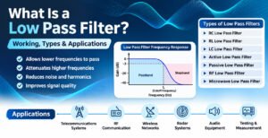
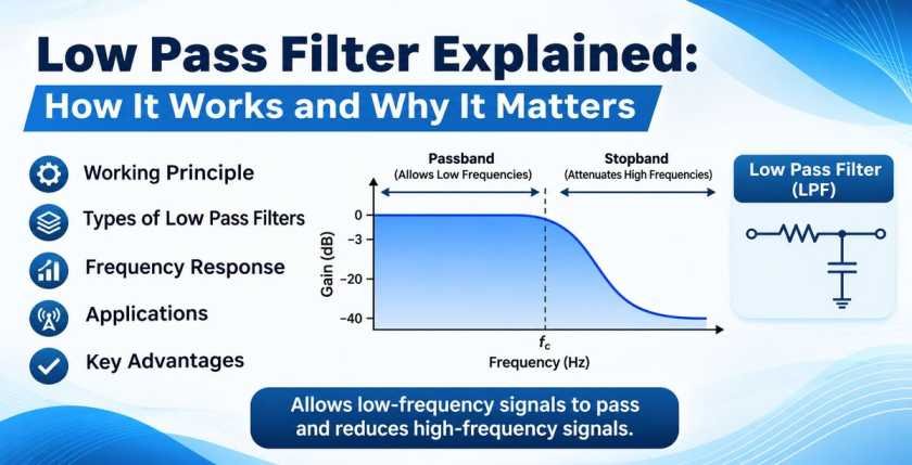
A Low Pass Filter (LPF) is an electronic filter that allows low-frequency signals to pass through with minimal attenuation while reducing or blocking signals above a predetermined frequency.
The frequency at which the filter begins to significantly attenuate the input signal is known as the cutoff frequency.
In simple terms, a low pass filter separates the required lower-frequency signals from unwanted higher-frequency components.
For example, if a low pass filter has a cutoff frequency of 1 GHz, signals below 1 GHz are generally allowed to pass, while signals above 1 GHz experience increasing attenuation. The actual response depends on the filter design and its specifications.
Low pass filters are commonly used in applications where signal quality, frequency control and interference reduction are important.
Key Characteristics of a Low Pass Filter
Some important characteristics of low pass filters include:
- Cutoff Frequency: The frequency at which the filter response reaches its specified cutoff point, commonly -3 dB for standard filter responses.
- Passband: The frequency range in which signals pass through with relatively low attenuation.
- Stopband: The frequency range in which unwanted signals are significantly attenuated.
- Insertion Loss: The reduction in signal power caused by introducing the filter into a transmission path.
- Return Loss: A measurement indicating how much input signal power is reflected because of impedance mismatch.
- Roll-Off Rate: The rate at which the filter attenuates signals beyond its cutoff frequency.
- Impedance: The electrical impedance for which the filter is designed, commonly 50 Ohms in RF and microwave systems.
How Does a Low Pass Filter Work?
The working principle of a low pass filter is based on the frequency-dependent behaviour of electrical components.
Depending on the design, a low pass filter may use resistors, capacitors and inductors to control the movement of different frequency signals through an electronic circuit.
At lower frequencies, the circuit allows the desired signal to pass with minimal attenuation. As the input frequency increases beyond the cutoff frequency, the filter progressively reduces the signal amplitude.
In RF and microwave systems, specialized filter structures are designed to provide controlled frequency responses and suppress unwanted high-frequency signals.
Working Principle of a Low Pass Filter
The working process can be explained in three stages:
1. Low-Frequency Signal Transmission
When a low-frequency signal enters the filter, the circuit allows it to pass through with relatively low attenuation. These frequencies fall within the filter’s passband.
2. Cutoff Frequency
As the input frequency approaches the cutoff frequency, the output signal begins to decrease. For a standard first-order filter, the amplitude is approximately 70.7% of its passband value at the -3 dB cutoff frequency.
3. High-Frequency Signal Attenuation
When the input frequency exceeds the cutoff frequency, the filter increasingly reduces the signal amplitude. Frequencies within the stopband are attenuated according to the filter’s design and order.
This process helps maintain the required frequency range and minimize unwanted signal components.
Understanding the Cutoff Frequency of a Low Pass Filter
The cutoff frequency is one of the most important specifications of a low pass filter.
It determines the boundary between the filter’s passband and its transition towards the stopband.
For a typical first-order RC low pass filter, the cutoff frequency is calculated using the following formula:
fc = 1 / (2πRC)
Where:
- fc = Cutoff frequency in Hertz (Hz)
- R = Resistance in Ohms (Ω)
- C = Capacitance in Farads (F)
- π = Mathematical constant approximately equal to 3.14159
Example of Cutoff Frequency Calculation
Consider an RC low pass filter with:
- Resistance (R) = 1 kΩ
- Capacitance (C) = 0.1 µF
Using the formula:
fc = 1 / (2 × 3.14159 × 1000 × 0.0000001)
The cutoff frequency is approximately:
fc = 1,591.5 Hz
This means the filter allows signals below approximately 1.59 kHz to pass with relatively low attenuation, while higher-frequency signals are progressively reduced.
For RF and microwave low pass filters, cutoff frequency depends on the selected filter topology, electrical design, transmission-line characteristics and physical structure.
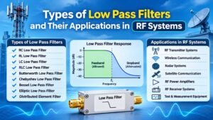
Types of Low Pass Filters
Low pass filters are available in different designs depending on their operating frequency, circuit requirements, signal characteristics and application.
Understanding the different types helps engineers select the appropriate filtering solution.
1. RC Low Pass Filter
An RC low pass filter uses a resistor and capacitor to attenuate high-frequency signals.
It is one of the simplest filter designs and is commonly used in low-frequency electronic circuits, audio applications and signal conditioning.
Its cutoff frequency is determined by the resistance and capacitance values.
2. RL Low Pass Filter
An RL low pass filter uses a resistor and inductor to control signal frequency.
The inductor offers increasing opposition to higher-frequency signals, allowing lower-frequency components to pass more effectively.
RL filters are used in selected electronic circuits and signal-processing applications.
3. LC Low Pass Filter
An LC low pass filter consists of inductors and capacitors.
It is widely used in applications requiring better frequency selectivity and improved high-frequency attenuation compared with simple first-order circuits.
LC filter designs are especially important in RF and microwave engineering, where accurate frequency control is required.
4. Active Low Pass Filter
An active low pass filter uses active electronic components such as operational amplifiers along with resistors and capacitors.
These filters can provide signal amplification, buffering and controlled frequency response.
They are commonly used in audio systems, instrumentation and electronic signal-processing circuits.
5. Passive Low Pass Filter
A passive low pass filter uses passive components such as resistors, capacitors and inductors without requiring an external power supply for its filtering operation.
Passive filters are commonly used in RF circuits, microwave systems and electronic communication equipment.
6. RF Low Pass Filter
An RF low pass filter is specifically designed to operate at radio frequencies.
It allows the required RF frequency range to pass while attenuating unwanted higher-frequency components, harmonics and interference.
RF low pass filters are commonly used in transmitters, receivers, wireless communication equipment, RF test systems and antenna networks.
7. Microwave Low Pass Filter
A microwave low pass filter operates at microwave frequencies and requires specialized electrical and mechanical design.
Depending on the frequency range and performance requirements, these filters may use distributed-element structures, transmission lines, waveguide-based designs or other microwave filter technologies.
They are used in radar systems, satellite communication, microwave links and advanced wireless communication equipment.
Low Pass Filter Frequency Response
Frequency response describes how a low pass filter behaves when different input frequencies are applied.
It is generally represented using a frequency response graph, showing frequency on the horizontal axis and signal gain or attenuation on the vertical axis.
A typical low pass filter frequency response contains three main regions.
Passband Region
The passband is the frequency range in which the filter allows signals to pass with relatively low attenuation.
The required signal frequencies are generally located within this region.
Transition Region
The transition region is the frequency range between the passband and stopband.
In this region, the filter progressively reduces the signal amplitude.
Stopband Region
The stopband is the frequency range where the filter provides significant attenuation.
It helps suppress unwanted high-frequency signals and harmonics.
The sharpness of the transition depends on the filter order, design topology and selected filter response.
What Is the Difference Between First-Order, Second-Order and Higher-Order Low Pass Filters?
The order of a low pass filter determines how quickly its response decreases beyond the cutoff frequency.
A higher-order filter generally provides a steeper attenuation slope, allowing better separation between the passband and stopband.
| Filter Order | Typical Roll-Off Rate |
|---|---|
| First Order | 20 dB per decade |
| Second Order | 40 dB per decade |
| Third Order | 60 dB per decade |
| Fourth Order | 80 dB per decade |
| Fifth Order | 100 dB per decade |
These values represent the typical asymptotic roll-off rates of standard filter responses.
Higher-order filters are useful when stronger attenuation is required over a relatively narrow frequency transition.
However, filter order also influences design complexity, component tolerances, insertion loss and overall system performance.
Common Low Pass Filter Responses
Different filter responses are selected according to the required frequency characteristics.
Butterworth Low Pass Filter
A Butterworth filter provides a maximally flat passband response without ripple.
It is commonly selected when smooth frequency response is important.
Chebyshev Low Pass Filter
A Chebyshev filter provides a steeper transition between the passband and stopband compared with a Butterworth filter of the same order.
It allows a trade-off between passband ripple and frequency selectivity.
Bessel Low Pass Filter
A Bessel filter is designed to provide a relatively constant group delay and good phase characteristics.
It is useful in applications where waveform shape and signal timing are important.
Elliptic Low Pass Filter
An elliptic filter provides a sharp transition between passband and stopband by allowing ripple in both regions.
It is useful when high selectivity is required within a limited filter order.
Applications of Low Pass Filters
Low pass filters are essential components in many electronic and communication systems. Their ability to control unwanted frequencies makes them valuable across several industries.
1. RF and Microwave Communication Systems
RF low pass filters are used in radio frequency communication systems to suppress unwanted high-frequency components and harmonics.
They help maintain signal quality and support reliable operation in RF transmission and reception systems.
2. Telecommunications Infrastructure
Telecommunication equipment operates with multiple frequency bands and complex signal environments.
Low pass filters help manage unwanted frequency components in communication equipment, RF modules and signal-processing circuits.
3. Wireless Communication Systems
Wireless communication devices require effective frequency management to reduce interference and improve signal integrity.
Low pass filters are used in RF front-end circuits, wireless modules and related communication equipment.
4. Radar Systems
Radar systems operate using carefully controlled RF and microwave signals.
Low pass filters can be used in signal conditioning and RF subsystems to suppress unwanted high-frequency components and harmonics.
5. Audio Equipment
In audio systems, low pass filters are used to remove unwanted high-frequency components and control audio frequency ranges.
They are commonly found in subwoofer circuits, audio amplifiers and sound-processing equipment.
6. Power Supply Circuits
Low pass filters help reduce high-frequency noise and ripple in selected power supply and electronic circuits.
This helps provide cleaner electrical signals to sensitive components.
7. Signal Processing Systems
Low pass filters are widely used in analog and digital signal processing.
They can reduce unwanted high-frequency noise, smooth signals and serve as anti-aliasing filters before analog-to-digital conversion.
8. Satellite Communication
Satellite communication systems use RF and microwave components to transmit and receive signals over long distances.
Low pass filters support frequency control and help suppress unwanted signal components within selected communication subsystems.
Importance of Low Pass Filters in RF and Microwave Engineering
In RF and microwave engineering, signal quality and frequency management directly influence system performance.
Unwanted high-frequency components can create interference, affect adjacent frequency bands and reduce the efficiency of communication equipment.
Low pass filters help address these challenges through controlled frequency attenuation.
Some important benefits include:
Harmonic Suppression: Low pass filters can reduce unwanted higher-order harmonics generated by RF transmitters and nonlinear electronic circuits.
Interference Reduction: They help attenuate unwanted high-frequency signals that may affect sensitive communication equipment.
Signal Quality Improvement: By controlling unwanted frequency components, filters support cleaner signal transmission and reception.
Frequency Management: They help engineers maintain the required frequency characteristics within RF and microwave systems.
System Protection: Proper filtering can help prevent unwanted out-of-band energy from reaching sensitive downstream circuits.
Important Specifications to Consider When Selecting a Low Pass Filter
Selecting the right low pass filter requires understanding the electrical and mechanical requirements of the application.
For RF and microwave applications, engineers should evaluate the following specifications.
| Specification | Description |
|---|---|
| Cutoff Frequency | Frequency at which the filter reaches its specified cutoff point |
| Operating Frequency Range | Frequency range over which the filter is designed to operate |
| Passband Insertion Loss | Signal loss within the specified passband |
| Stopband Attenuation | Amount of unwanted signal reduction in the stopband |
| Return Loss | Indicates input impedance matching and reflected signal power |
| Impedance | Commonly 50 Ohms in RF and microwave applications |
| Power Handling | Maximum power the filter can safely handle under specified conditions |
| VSWR | Voltage Standing Wave Ratio, indicating impedance matching quality |
| Connector Type | Interface compatibility, such as SMA, N-type or other RF connectors |
| Operating Temperature | Temperature range within which the filter meets its specifications |
Choosing a filter based on these parameters helps ensure compatibility with the intended communication or electronic system.
Difference Between Low Pass Filter and High Pass Filter
Low pass filters and high pass filters are designed to control different portions of the frequency spectrum.
A low pass filter allows lower-frequency signals to pass while attenuating higher-frequency signals.
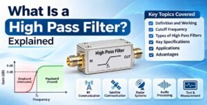
A high pass filter allows higher-frequency signals to pass while attenuating lower-frequency signals.
| Parameter | Low Pass Filter | High Pass Filter |
|---|---|---|
| Main Function | Allows low frequencies to pass | Allows high frequencies to pass |
| Attenuates | Frequencies above cutoff | Frequencies below cutoff |
| Passband | Below cutoff frequency | Above cutoff frequency |
| Applications | Harmonic suppression, audio and RF systems | Signal coupling, noise control and RF systems |
| Frequency Response | Decreases beyond cutoff | Increases towards the passband |
Both filters are important in electronic and RF engineering, and their selection depends on the frequency requirements of the application.
Advantages of Using Low Pass Filters
Low pass filters offer several advantages in electronic and communication systems.
- Reduce unwanted high-frequency signal components.
- Help suppress harmonics in RF transmission systems.
- Improve signal quality by controlling frequency interference.
- Support effective frequency management.
- Reduce high-frequency noise in selected electronic circuits.
- Provide reliable filtering in RF and microwave applications.
- Support efficient operation of communication and signal-processing equipment.
- Can be designed for different operating frequencies and performance requirements.
Factors Affecting Low Pass Filter Performance
The performance of a low pass filter depends on several electrical, mechanical and environmental factors.
Component Tolerances: Variations in resistor, capacitor and inductor values can affect the actual cutoff frequency and filter response.
Impedance Matching: Impedance mismatch between the filter and connected equipment can increase reflected power and affect performance.
Insertion Loss: Excessive insertion loss can reduce the desired signal level.
Temperature Variations: Changes in operating temperature can influence component characteristics and electrical performance.
Filter Design: The selected topology, filter order and construction method determine frequency selectivity and attenuation characteristics.
Manufacturing Quality: Precision manufacturing and consistent component selection are important for achieving reliable electrical performance, especially at RF and microwave frequencies.
How to Choose the Right Low Pass Filter for Your Application
Selecting an appropriate low pass filter requires evaluating the requirements of the complete electronic or communication system.
Consider these important factors before making a selection:
- Determine the Required Cutoff Frequency: Identify the maximum frequency that should pass through the filter.
- Check the Operating Frequency Range: Ensure the selected filter supports the intended frequency range.
- Evaluate Insertion Loss: Select a filter with suitable passband insertion loss to minimize unwanted signal reduction.
- Check Stopband Attenuation: Determine how much suppression is required for unwanted high-frequency signals.
- Verify Impedance Compatibility: Ensure the filter matches the impedance of the connected RF equipment, commonly 50 Ohms.
- Consider Power Requirements: Check the maximum input power and operating conditions.
- Select Suitable Connectors: Ensure mechanical and electrical compatibility with the existing RF setup.
- Evaluate Environmental Conditions: Consider operating temperature, humidity and installation requirements.
A carefully selected low pass filter can improve frequency control, reduce unwanted signal components and support dependable system operation.
Role of Low Pass Filters in Modern Communication Technology
Modern communication infrastructure depends on accurate frequency management and reliable RF performance.
With the growth of wireless networks, satellite communication, radar technology, industrial wireless systems and advanced telecommunications, filtering solutions have become increasingly important.
Low pass filters support these technologies by helping control unwanted high-frequency components and harmonics.
In RF and microwave applications, filter performance must be considered alongside other components, including antennas, RF cables, connectors, attenuators, power dividers and other transmission-line accessories.
The correct combination of these components helps engineers develop reliable and efficient communication infrastructure.
Why Choose Quality RF Low Pass Filters?
The performance of an RF communication system depends on the quality and compatibility of its individual components.
Selecting a suitable low pass filter requires attention to cutoff frequency, insertion loss, return loss, stopband attenuation, impedance and power-handling requirements.
For professional RF and microwave applications, it is important to select filtering components that meet the electrical and mechanical requirements of the intended system.
SRFS Teleinfra provides RF and microwave components and communication infrastructure solutions for various engineering and industrial applications.
Explore the RF and communication solutions available at SRFS Teleinfra:
Website: https://www.srfsteleinfra.in/
For technical product information and application requirements, connect with the SRFS Teleinfra team.
Frequently Asked Questions (FAQs) About Low Pass Filters
1. What is a low pass filter?
A low pass filter is an electronic filter that allows signals below a specified cutoff frequency to pass while attenuating signals above that frequency. It is widely used in RF, microwave, audio and communication systems.
2. What is the main purpose of a low pass filter?
The main purpose of a low pass filter is to reduce unwanted high-frequency signals while allowing the required lower-frequency signals to pass through the circuit.
3. What is the cutoff frequency of a low pass filter?
The cutoff frequency is the frequency at which the filter reaches its specified attenuation point, commonly -3 dB for standard filter responses. It defines the transition from the passband towards the stopband.
4. What are the different types of low pass filters?
Common types include RC, RL, LC, active, passive, RF and microwave low pass filters. The appropriate type depends on the operating frequency and application requirements.
5. Where are low pass filters used?
Low pass filters are used in RF communication systems, microwave equipment, telecommunications infrastructure, radar systems, audio devices, power supplies and digital signal-processing applications.
6. Why are low pass filters important in RF systems?
Low pass filters are important in RF systems because they help suppress unwanted high-frequency signals and harmonics, control frequency components and support reliable signal transmission.
7. What is the difference between a low pass filter and a high pass filter?
A low pass filter allows frequencies below its cutoff frequency to pass, whereas a high pass filter allows frequencies above its cutoff frequency to pass.
8. What is insertion loss in a low pass filter?
Insertion loss is the reduction in signal power caused by inserting a filter into a transmission path. Lower insertion loss within the passband is generally desirable.
9. What is the difference between active and passive low pass filters?
Active low pass filters use active components such as operational amplifiers along with passive components and can provide amplification. Passive low pass filters use resistors, capacitors and inductors without requiring an external power supply for filtering.
10. How do you select the right RF low pass filter?
To select the right RF low pass filter, evaluate cutoff frequency, operating frequency range, insertion loss, stopband attenuation, impedance, power handling, return loss, connector type and environmental requirements.
Conclusion
Low pass filters are essential components in modern electronic, RF and microwave engineering systems. By allowing desired lower-frequency signals to pass while attenuating unwanted higher-frequency components, they help maintain signal quality and improve frequency control.
From simple RC circuits to advanced RF and microwave filtering solutions, low pass filters serve a wide range of applications in telecommunications, wireless communication, radar, satellite systems and electronic equipment.
Understanding their working principles, types, cutoff frequency, frequency response and technical specifications helps engineers select the right filtering solution for their applications.
For reliable RF system performance, choosing a low pass filter that meets the required electrical, mechanical and environmental specifications is essential.
SRFS Teleinfra supports the RF and microwave engineering industry with a range of components and communication infrastructure solutions designed for diverse technical applications.