
RF Power Splitter
At SRFS TELEINFRA, we offer high-performance RF Power Splitters designed for efficient signal distribution in telecom, DAS, IBS, BTS, public safety communication, and wireless network applications. Our power splitters are engineered to divide RF signals evenly with minimal insertion loss, excellent isolation, and low VSWR for stable network performance.
Our range includes 2-Way, 3-Way, and 4-Way Power Splitters available in multiple frequency ranges including 100–1000 MHz, 698–4000 MHz, and 550–6000 MHz. These splitters are suitable for both indoor and outdoor deployments with rugged IP65-rated housing and low PIM performance for modern 4G and 5G networks.
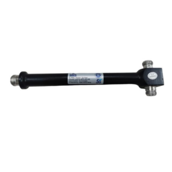
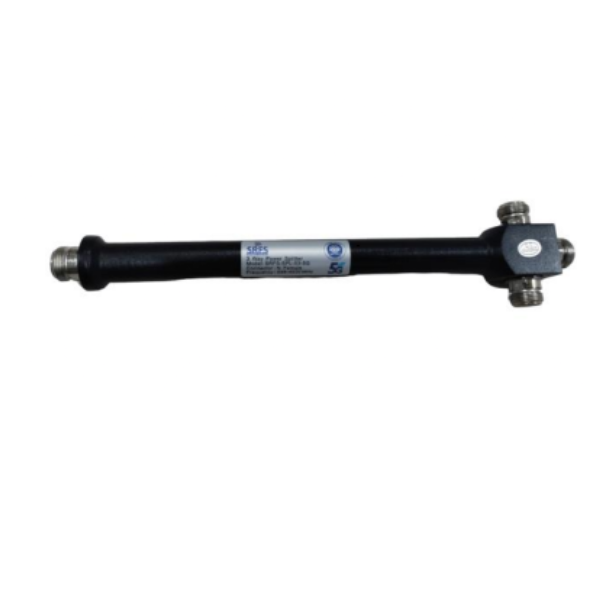
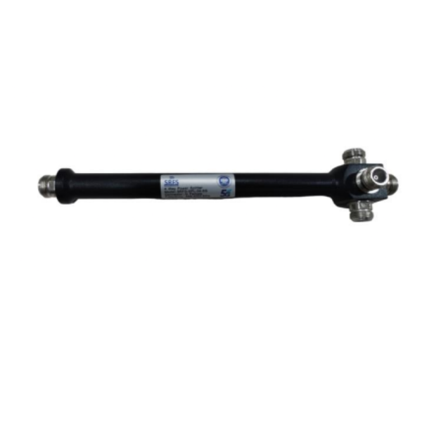
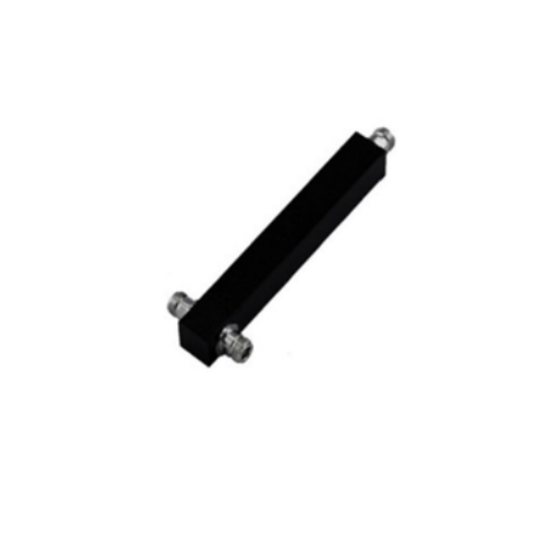
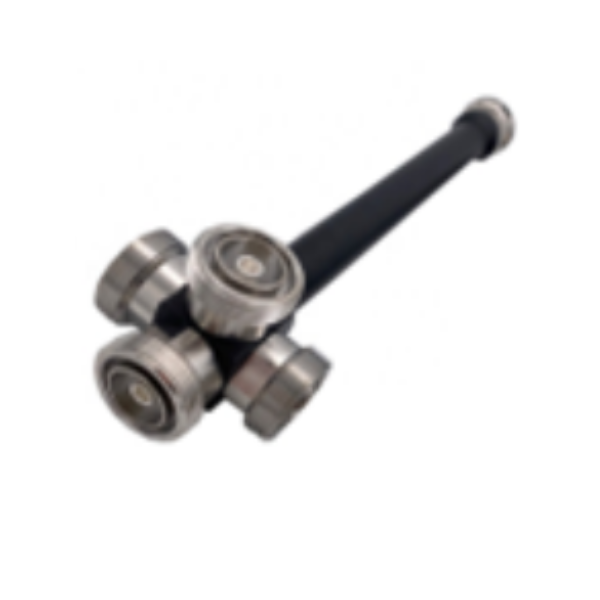
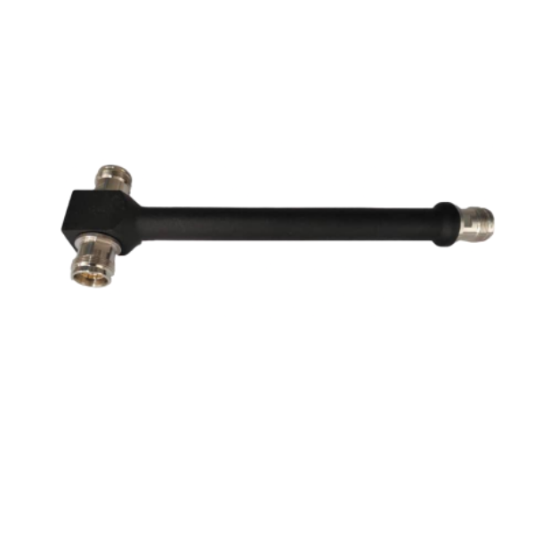
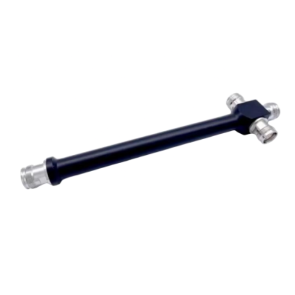
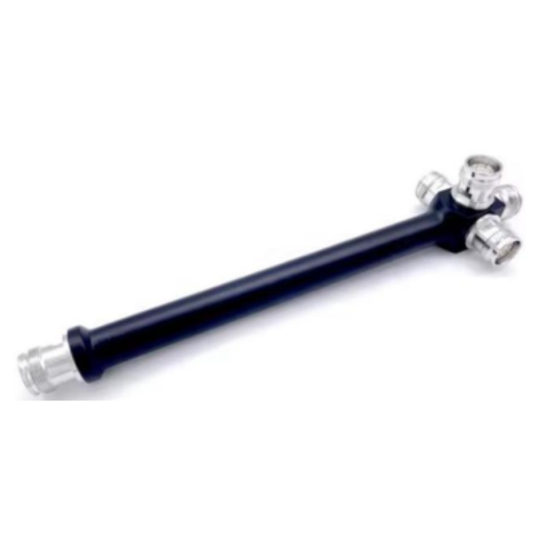
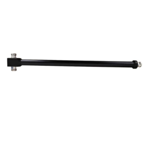
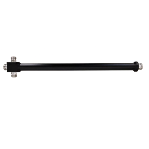
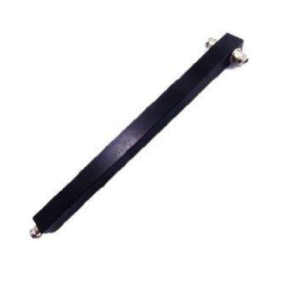
What is RF Power Splitter?
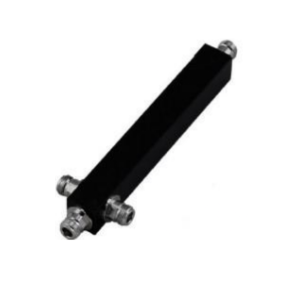
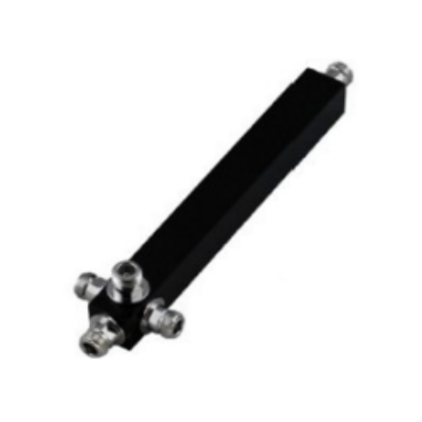
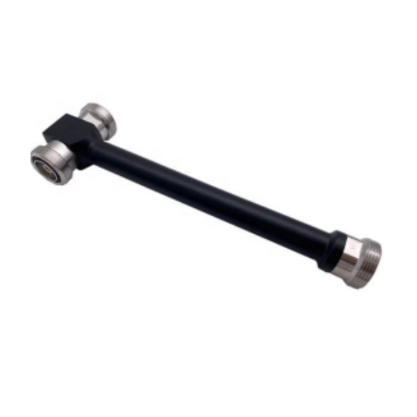
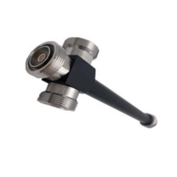
RF Power Splitter is a passive RF component used to divide a single radio frequency (RF) signal into multiple output signals while maintaining proper signal integrity and impedance matching. It is widely used in telecom, wireless communication, Distributed Antenna Systems (DAS), indoor coverage systems, RF testing, and 4G/5G network infrastructure.
Types of RF Power Splitters
RF Power Splitters are classified based on the number of output ports, frequency range, and application requirements.
- 2-Way RF Power Splitter
- 3-Way RF Power Splitter
- 4-Way RF Power Splitter
RF Power Splitters Product Specifications
| Power Splitter Type | Frequency Range | Connector Type | Application |
|---|---|---|---|
| 2-Way Power Splitter | 698-4000 MHz | N Female | DAS, IBS & Telecom Networks |
| 3-Way Power Splitter | 698-4000 MHz | N Female | Wireless RF Signal Distribution |
| 4-Way Power Splitter | 698-4000 MHz | N Female | 4G/5G Network Infrastructure |
| 2 Way Power Splitter Square Type | 698-4000 MHz | N Female | Outdoor RF Communication Systems |
| 3 Way Power Splitter Square Type | 698-4000 MHz | N Female | Telecom & DAS Applications |
| 4 Way Power Splitter Square Type | 698-4000 MHz | N Female | RF Multi-Antenna Distribution |
| 2 Way DIN-F Power Splitter | 698-4000 MHz | DIN Female | LTE & 5G Telecom Systems |
| 3 Way DIN-F Power Splitter | 698-4000 MHz | DIN Female | Indoor & Outdoor RF Networks |
| 4 Way DIN-F Power Splitter | 698-4000 MHz | DIN Female | Distributed Antenna Systems |
| 2-Way Power Splitter 4.3-10 Female | 698-4000 MHz | 4.3-10 Female | Low PIM Telecom Applications |
| 3-Way Power Splitter 4.3-10 Female | 698-4000 MHz | 4.3-10 Female | 5G RF Signal Distribution |
| 4-Way Power Splitter 4.3-10 Female | 698-4000 MHz | 4.3-10 Female | High Performance RF Networks |
| 350-4200 MHz 2 Way Power Splitter | 350-4200 MHz | N Female | Wideband RF Communication |
| 350-4200 MHz 3 Way Power Splitter | 350-4200 MHz | N Female | Broadband Telecom Systems |
Technical Specifications
- Frequency Range: 698–4000 MHz / 350–4200 MHz
- Split Types: 2-Way, 3-Way, 4-Way
- Impedance: 50 Ohm
- Connector Types: N Female, DIN Female, 4.3-10 Female
- Insertion Loss: ≤0.4 dB to ≤6.0 dB
- VSWR: ≤1.2 to ≤1.35
- Isolation: ≥20 dB
- Power Handling Capacity: Up to 300W
- PIM Performance: ≤ -150 dBc / ≤ -155 dBc
- Operating Temperature: -35°C to +85°C
- Protection Rating: IP65 Indoor & Outdoor Use
- Housing Material: Aluminum Alloy with Black Paint Finish
- Humidity Range: 5% to 95% RH
- Application Support: LTE, GSM, DAS, IBS, 4G & 5G Networks
Applications of RF Power Splitters
- Distributed Antenna Systems (DAS)
- Indoor Building Solutions (IBS)
- 4G LTE & 5G Telecom Infrastructure
- Public Safety Communication Networks
- RF Testing Laboratories
- Wireless Communication Systems
- Base Station Antenna Distribution
- Repeater and Booster Systems
- Multi-Antenna RF Networks
- Microwave Communication Systems
Key Performance Factors
1. Insertion Loss
Insertion loss refers to the amount of signal power lost during signal splitting. Lower insertion loss ensures better RF efficiency and stronger output signals.
2. VSWR (Voltage Standing Wave Ratio)
A low VSWR indicates good impedance matching and minimal signal reflection, improving overall network stability.
3. Isolation
Isolation measures how effectively the output ports are separated from each other. High isolation reduces interference between connected devices.
4. Power Handling Capacity
RF power splitters should support high RF power levels for telecom and base station applications without performance degradation.
5. Low PIM Performance
Low Passive Intermodulation (PIM) is critical for LTE and 5G networks to minimize signal distortion and improve network quality.
6. Frequency Range
Wideband splitters support multiple frequency bands, making them suitable for modern multi-band telecom systems.
7. Environmental Protection
Outdoor RF systems require rugged IP65-rated housings for protection against dust, moisture, and harsh weather conditions
Working Principle of RF Power Splitters
An RF Power Splitter works by dividing a single input RF signal into multiple output signals with equal or specified power levels while maintaining proper impedance matching.
It uses internal transmission lines, transformers, or resistor networks to distribute the signal efficiently across output ports.
The splitter minimizes signal loss, maintains low VSWR, and provides good isolation between output ports to prevent interference. RF power splitters are commonly available in 2-way, 3-way, and 4-way configurations for telecom, DAS, IBS, and wireless communication systems.
They help ensure stable signal transmission and balanced RF performance in modern 4G, LTE, and 5G network infrastructures.
Why Choose us
Wide Frequency Support
Designed to support broadband telecom frequencies for 2G, 3G, 4G LTE, 5G, DAS, and wireless communication systems.
Excellent Signal Stability
Manufactured using precision RF engineering for stable signal distribution, low VSWR, and reliable network performance.
Durable & Weather-Resistant
Built with rugged IP-rated housing and corrosion-resistant materials for long-term indoor and outdoor telecom applications.
High Power Handling Capability
Suitable for telecom towers, antenna systems, IBS, and RF distribution networks requiring stable high-power RF performance.
Frequently Asked Questions
A power splitter is an RF device used to divide one input signal into multiple output signals while maintaining signal quality and impedance matching.
They are widely used in telecom towers, DAS systems, IBS networks, antenna systems, Wi-Fi installations, and 4G/5G communication networks.
Most RF power splitters are designed with standard 50 Ohm impedance for telecom and RF applications.
RF power splitters commonly support frequencies from 698 MHz to 4000 MHz depending on the model and application.
Low insertion loss minimizes signal attenuation and improves overall RF transmission efficiency and network performance.
VSWR (Voltage Standing Wave Ratio) measures impedance matching and signal reflection performance in RF systems.
Yes, modern RF power splitters are designed for 4G LTE and 5G telecom infrastructure applications.
Most telecom power splitters use N Female connectors for stable RF connectivity and low signal loss.
Yes, many RF power splitters are manufactured with IP65-rated weatherproof protection for outdoor telecom environments.
SRFS Teleinfra offers high-quality RF power splitters with low insertion loss, durable construction, stable signal performance, and reliable telecom connectivity solutions.