RF and microwave applications because it can provide better filtering performance than simple RC and RL circuits.
The inductor and capacitor work together to control the frequency response of the circuit.
LC filters are particularly useful when low insertion loss and effective high-frequency attenuation are required.
Key Characteristics:
- Uses inductors and capacitors
- Suitable for higher-frequency applications
- Provides improved filtering performance
- Can offer a steeper frequency response with multiple stages
- Commonly designed for RF impedance matching
Applications:
- RF transmitter circuits
- Wireless communication equipment
- Harmonic suppression
- RF power amplifiers
- Microwave communication systems
- Antenna feed networks
LC low pass filters are commonly used at the output of RF power amplifiers to reduce unwanted harmonic frequencies.
4. RLC Low Pass Filter
An RLC low pass filter combines resistors, inductors and capacitors to provide controlled frequency filtering.
The resistor helps control damping, while the inductor and capacitor determine the frequency-dependent response.
Depending on the component arrangement and circuit order, RLC filters can provide different levels of selectivity and attenuation.
Key Characteristics:
- Combines resistive and reactive components
- Offers flexibility in circuit design
- Can control resonance and damping
- Suitable for frequency-selective applications
Applications:
- RF signal conditioning
- Electronic communication systems
- Harmonic filtering
- Analog signal processing
- High-frequency circuit design
5. Butterworth Low Pass Filter
A Butterworth low pass filter is designed to provide a maximally flat magnitude response in the passband.
This means the filter maintains a smooth and consistent signal response below its cutoff frequency without introducing passband ripples.
The attenuation increases gradually beyond the cutoff frequency, depending on the filter order.
Key Characteristics:
- Flat passband response
- No passband ripple
- Smooth frequency transition
- Predictable attenuation characteristics
- Suitable for applications requiring consistent signal amplitude
Applications:
- RF communication circuits
- Audio signal processing
- Wireless receiver systems
- Analog and digital signal processing
- RF measurement equipment
Butterworth filters are commonly selected when maintaining signal amplitude across the passband is more important than achieving an extremely sharp cutoff.
6. Chebyshev Low Pass Filter
A Chebyshev low pass filter provides a sharper transition between the passband and stopband compared with a Butterworth filter of the same order.
It achieves this improved selectivity by allowing controlled ripple in the passband (Type I) or stopband (Type II).
Key Characteristics:
- Sharper cutoff than Butterworth filters of equal order
- Controlled ripple characteristics
- Improved frequency selectivity
- Suitable for applications requiring stronger out-of-band rejection
Applications:
- RF receiver circuits
- Wireless communication systems
- Microwave filter networks
- Spectrum management
- Signal separation applications
Chebyshev filters are useful in RF applications where unwanted frequencies need to be rejected more aggressively while maintaining an acceptable level of passband ripple.
7. Bessel Low Pass Filter
A Bessel low pass filter is designed to provide an approximately linear phase response and good group delay characteristics within its passband.
Unlike Butterworth and Chebyshev filters, which primarily focus on magnitude response, Bessel filters prioritize signal waveform preservation.
Key Characteristics:
- Nearly constant group delay in the passband
- Good transient response
- Reduced waveform distortion
- Smooth frequency response
- Useful for time-sensitive signals
Applications:
- High-speed communication circuits
- Pulse transmission systems
- RF signal processing
- Measurement instruments
- Communication test equipment
Bessel filters are particularly valuable when preserving the shape and timing of transmitted signals is important.
8. Elliptic (Cauer) Low Pass Filter
An elliptic low pass filter, also known as a Cauer filter, provides a very sharp transition between the passband and stopband.
It achieves high selectivity by allowing controlled ripple in both the passband and stopband.
For a given filter order and specified ripple and attenuation, elliptic filters generally provide the narrowest transition band among the classical filter approximations.
Key Characteristics:
- Very sharp cutoff response
- High frequency selectivity
- Ripple in both passband and stopband
- Compact implementation for demanding filtering requirements
Applications:
- RF communication systems
- Microwave circuits
- High-selectivity receivers
- Frequency management systems
- Advanced signal processing
Elliptic filters are suitable when strong frequency rejection is required within a limited circuit size or filter order.
9. Distributed Element Low Pass Filter
Distributed-element low pass filters are designed using transmission-line structures instead of relying entirely on individual lumped components.
These filters are especially useful at microwave frequencies, where the physical dimensions of inductors and capacitors can become significant compared with the signal wavelength.
Common distributed filter structures include:
- Stepped-impedance filters
- Stub-based filters
- Microstrip filters
- Stripline filters
Key Characteristics:
- Suitable for microwave frequency ranges
- Can be integrated into RF printed circuit boards
- Supports compact RF circuit designs
- Uses transmission-line characteristics
- Can be optimized for specific frequency bands
Applications:
- Microwave communication systems
- Radar equipment
- Satellite communication
- RF front-end modules
- Wireless infrastructure
- High-frequency PCB designs
Distributed-element filters are particularly important in modern RF and microwave engineering, where performance and circuit integration are critical.
Comparison of Different Types of Low Pass Filters
The following table compares the major low pass filter designs and their typical characteristics.
| Filter Type | Main Components / Design | Key Advantage | Common Applications |
|---|---|---|---|
| RC Filter | Resistor, Capacitor | Simple and economical | Audio and signal conditioning |
| RL Filter | Resistor, Inductor | Inductive filtering | Power and noise filtering |
| LC Filter | Inductor, Capacitor | Low-loss filtering potential | RF and microwave circuits |
| RLC Filter | Resistor, Inductor, Capacitor | Damping and response control | Signal processing |
| Butterworth | Filter network | Flat passband | RF and communication |
| Chebyshev | Filter network | Sharp transition | RF receivers |
| Bessel | Filter network | Good phase response | Pulse transmission |
| Elliptic | Filter network | Very sharp cutoff | High-selectivity RF systems |
| Distributed Element | Transmission lines | Microwave integration | Radar and satellite systems |
Note: RC, RL, LC and RLC describe circuit implementations, while Butterworth, Chebyshev, Bessel and elliptic describe filter response approximations. These categories can overlap.
Applications of Low Pass Filters in RF Systems
Low pass filters play a critical role in modern RF systems by controlling signal bandwidth, suppressing unwanted frequencies and improving overall communication performance.
Some important applications include:
1. RF Transmitter Systems
RF transmitters generate signals that may contain unwanted harmonic frequencies. These harmonics can interfere with other communication channels and affect regulatory compliance.
Low pass filters are commonly placed at the output of RF power amplifiers to attenuate unwanted harmonics while allowing the desired transmission frequency to pass.
Benefits:
- Reduces unwanted harmonic emissions
- Improves transmitted signal quality
- Helps control out-of-band emissions
- Supports cleaner RF transmission
2. Wireless Communication Networks
Wireless communication systems operate across multiple frequency bands. Unwanted high-frequency signals can affect receiver performance and create interference.
Low pass filters help control signal bandwidth and reject frequencies outside the required operating range.
Applications include:
- 4G and 5G communication infrastructure
- Wireless base stations
- Telecom radio equipment
- RF transceiver modules
- Wireless networking devices
3. Radar Systems
Radar systems transmit and receive RF signals to detect objects, determine distances and measure movement.
Low pass filters are used in different radar signal-processing stages to reduce unwanted high-frequency components and limit the bandwidth of selected signals.
They can also be used in intermediate-frequency and baseband processing circuits.
4. Satellite Communication Systems
Satellite communication systems require reliable signal transmission across long distances and carefully controlled frequency bands.
Low pass filters are used in RF and microwave subsystems to suppress unwanted harmonics, reduce out-of-band signals and support proper signal conditioning.
Applications include:
- Satellite transponders
- Ground station equipment
- RF communication modules
- Microwave transmission systems
- Satellite navigation equipment
5. RF Power Amplifiers
RF power amplifiers increase signal strength before transmission. However, nonlinear amplifier operation can generate unwanted harmonic frequencies.
A low pass filter at the amplifier output helps suppress these harmonics and improves spectral cleanliness.
It is an important component in transmitter designs where unwanted emissions must be controlled.
6. RF Receiver Systems
RF receivers are designed to detect and process signals within specific frequency ranges.
Low pass filters are used in receiver signal chains, especially in intermediate-frequency and baseband stages, to limit bandwidth and reduce unwanted high-frequency noise.
Their performance helps improve signal processing and communication reliability.
7. Test and Measurement Equipment
RF testing instruments require accurate frequency control and signal conditioning.
Low pass filters are used in spectrum analyzers, signal generators, network analyzers and other RF measurement equipment.
They help reduce unwanted frequency components and improve the reliability of measurement operations.
Important Technical Parameters of RF Low Pass Filters
When selecting a low pass filter for an RF application, engineers must consider several electrical and mechanical specifications.
These parameters determine whether the filter will perform correctly within the intended communication system.
1. Cutoff Frequency
Cutoff frequency is the frequency at which the filter response reaches a specified attenuation relative to its passband level.
For many standard filter designs, this point is defined at approximately -3 dB.
Selecting the correct cutoff frequency ensures that the desired operating frequencies pass through the filter.
2. Insertion Loss
Insertion loss refers to the reduction in signal power caused by inserting the filter into an RF transmission path.
It is generally measured in decibels (dB).
Lower insertion loss is desirable because it helps preserve the signal strength passing through the filter.
3. Return Loss
Return loss measures how effectively the filter matches the characteristic impedance of the connected RF system.
Poor impedance matching causes signal reflections, which can reduce overall system efficiency.
For many RF systems, 50-ohm impedance is commonly used.
4. Stopband Attenuation
Stopband attenuation indicates how effectively the filter suppresses unwanted frequencies above the cutoff region.
Higher stopband attenuation is important in applications where harmonic suppression and interference reduction are critical.
5. Passband Ripple
Passband ripple refers to variations in signal amplitude within the filter’s passband.
Some filter designs, such as Butterworth, offer a maximally flat passband, while Chebyshev and elliptic filters allow controlled ripple to achieve sharper frequency selectivity.
6. Power Handling Capability
Power handling describes the maximum RF power a filter can safely handle without performance degradation or physical damage.
This specification is particularly important in RF transmitters and high-power amplifier systems.
7. Operating Frequency Range
The operating frequency range defines the frequencies over which the filter is designed to perform according to its specified characteristics.
The selected filter must support the required RF frequency band.
How to Choose the Right Low Pass Filter for RF Applications
Selecting the right low pass filter requires evaluating the technical requirements of the overall RF system.
Here are some important factors to consider:
1. Determine the Operating Frequency: Identify the desired signal frequency and select a filter with an appropriate cutoff frequency.
2. Evaluate Insertion Loss: Choose a filter with low insertion loss to minimize signal attenuation.
3. Check Stopband Attenuation: Ensure the filter provides sufficient rejection of unwanted frequencies and harmonics.
4. Consider Impedance Matching: Verify that the filter impedance matches the connected RF components, commonly 50 ohms.
5. Evaluate Power Requirements: Select a filter that can safely handle the expected RF power levels.
6. Consider Physical Design: Check the connector type, mounting arrangement, size and environmental requirements.
7. Review Phase and Group Delay: For systems sensitive to signal timing and waveform distortion, evaluate the phase response and group delay.
8. Verify Environmental Conditions: Consider operating temperature, humidity, vibration and other environmental factors.
Choosing a suitable RF low pass filter helps improve system performance, reduce unwanted interference and maintain reliable signal transmission.
Low Pass Filters vs High Pass Filters vs Band Pass Filters
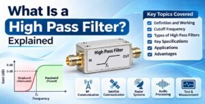
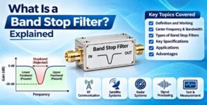
Low pass, high pass and band pass filters are three commonly used frequency-selective components in RF and electronic systems.
Although all three control signal frequencies, their operating principles are different.
Butterworth Filter Design | Tutorials on Electronics | Next Electronics
| Parameter | Low Pass Filter | High Pass Filter | Band Pass Filter |
|---|---|---|---|
| Signal Passed | Frequencies below cutoff | Frequencies above cutoff | Frequencies within selected band |
| Signal Attenuated | Higher frequencies | Lower frequencies | Frequencies outside the band |
| Main Purpose | High-frequency suppression | Low-frequency suppression | Frequency band selection |
| RF Applications | Harmonic suppression | Low-frequency noise rejection | Channel selection |
| Typical Usage | Transmitter output | RF signal conditioning | RF receivers |
Each filter type serves a different purpose, and the appropriate selection depends on the frequency requirements of the RF system.
Advantages of Low Pass Filters in RF Systems
Low pass filters offer several benefits in RF and communication applications.
- Harmonic Suppression: Helps reduce unwanted harmonics generated by RF transmitters and amplifiers.
- Noise Reduction: Attenuates unwanted high-frequency components.
- Signal Quality: Helps maintain the required frequency characteristics of communication signals.
- Interference Control: Reduces unwanted out-of-band signal components.
- System Protection: Helps prevent unwanted frequency components from reaching sensitive downstream circuits.
- Improved Communication Performance: Supports reliable operation of RF communication equipment.
- Flexible Design: Available in different circuit configurations and frequency response characteristics.
Common Challenges in RF Low Pass Filter Design
Although low pass filters provide several benefits, their design and implementation require careful engineering.
Some common challenges include:
1. Insertion Loss: Excessive insertion loss can reduce the available signal power.
2. Impedance Mismatch: Incorrect impedance matching can cause reflections and reduce transmission efficiency.
3. Component Tolerances: Variations in inductors and capacitors can affect the actual cutoff frequency and overall response.
4. Parasitic Effects: At high frequencies, unwanted capacitance and inductance can influence filter performance.
5. PCB Layout: Poor grounding, transmission-line routing and component placement can affect RF performance.
6. Power Limitations: High RF power levels can cause component heating and performance degradation.
To overcome these challenges, engineers must carefully select components, optimize circuit layouts and validate filter performance through RF testing.
Future Importance of Low Pass Filters in RF and Wireless Communication
As wireless communication technologies continue to develop, the importance of accurate frequency filtering is increasing.
Modern telecom infrastructure, advanced radar systems, satellite communication and high-frequency wireless applications require efficient RF components capable of maintaining signal quality across demanding operating conditions.
Low pass filters will continue to play an important role in:
- 5G and emerging 6G communication infrastructure
- Advanced RF front-end modules
- High-frequency microwave systems
- Satellite communication networks
- Radar and defence communication systems
- High-speed wireless connectivity
- RF testing and measurement solutions
Improvements in filter materials, manufacturing technologies and circuit integration are helping engineers develop smaller, more efficient and higher-performance filtering solutions.
Frequently Asked Questions (FAQs)
1. What are the main types of low pass filters?
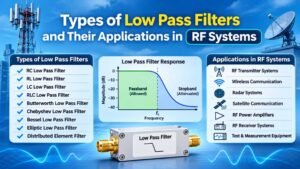
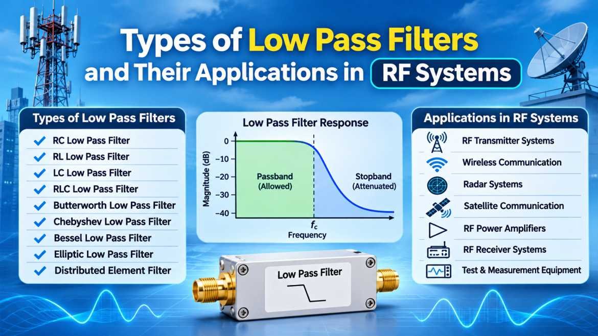
The main types include RC, RL, LC, RLC, Butterworth, Chebyshev, Bessel, elliptic and distributed-element low pass filters. Each type offers different frequency response characteristics and is suitable for specific applications.
2. What is the main purpose of a low pass filter in RF systems?
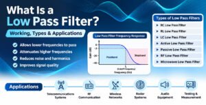
The primary purpose of a low pass filter in RF systems is to allow signals below a specified cutoff frequency to pass while attenuating unwanted higher-frequency signals. It is commonly used for harmonic suppression and bandwidth control.
3. Which low pass filter is best for RF applications?
LC, Butterworth, Chebyshev and distributed-element filters are commonly used in RF applications. The best choice depends on operating frequency, insertion loss, stopband attenuation, impedance matching and power handling requirements.
4. What is the cutoff frequency of a low pass filter?
The cutoff frequency is the frequency at which the filter begins to attenuate the signal significantly. For many standard filter responses, it is defined at the -3 dB point.
5. Why are LC low pass filters used in RF circuits?
LC low pass filters are used because they can provide low-loss frequency filtering and effective harmonic suppression. They are suitable for many RF transmitter, receiver and microwave circuit applications.
6. What is the difference between Butterworth and Chebyshev filters?
Butterworth filters provide a maximally flat passband response, while Chebyshev filters allow controlled ripple to achieve a sharper transition between the passband and stopband for a given filter order.
7. Can low pass filters be used in 5G communication systems?
Yes. Low pass filters can be used in 5G RF infrastructure for harmonic suppression, signal conditioning, bandwidth control and reducing unwanted frequency components in transmitter and receiver circuits.
8. What parameters should be checked before selecting an RF low pass filter?
Important parameters include cutoff frequency, insertion loss, return loss, stopband attenuation, impedance, power handling, operating temperature and connector configuration.
Conclusion
Low pass filters are essential components in modern RF and communication systems. They help control frequency ranges, suppress unwanted harmonics, reduce high-frequency interference and maintain signal quality.
Different types of low pass filters, including RC, RL, LC, RLC, Butterworth, Chebyshev, Bessel, elliptic and distributed-element designs, offer different advantages depending on the application.
For RF engineers and telecom equipment manufacturers, selecting the correct low pass filter requires careful consideration of cutoff frequency, insertion loss, return loss, stopband attenuation and power handling capability.
As wireless communication, radar, satellite and microwave technologies continue to advance, low pass filters will remain an important part of reliable and efficient RF system design.
SRFS Teleinfra provides RF and microwave components and telecom infrastructure solutions for modern communication requirements. Explore RF components, filters, cable assemblies, connectors and other communication solutions at www.srfsteleinfra.in.