In modern electronic, telecommunications, wireless communication, and RF engineering systems, maintaining signal quality is essential for reliable performance. Electronic devices and communication networks often operate with signals containing different frequencies, including unwanted high-frequency components, electrical noise, and interference. These unwanted signals can affect system performance, reduce signal clarity, and create communication errors. This is where Low Pass Filters play an important role.
A Low Pass Filter (LPF) is an electronic component or circuit designed to allow signals below a specific frequency to pass through while attenuating signals above that frequency. It helps eliminate unwanted high-frequency noise and interference while preserving the desired lower-frequency signals.
Low pass filters are widely used in RF communication systems, microwave applications, wireless networks, audio equipment, signal processing circuits, and electronic instrumentation. In telecommunications and RF engineering, RF low pass filters help control signal bandwidth, reduce unwanted harmonics, and improve the overall performance of communication equipment.
Understanding the working principle, types, specifications, and applications of low pass filters is important when selecting the right filtering solution for a particular electronic or communication system.
What Is a Low Pass Filter?
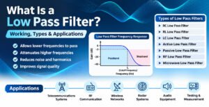
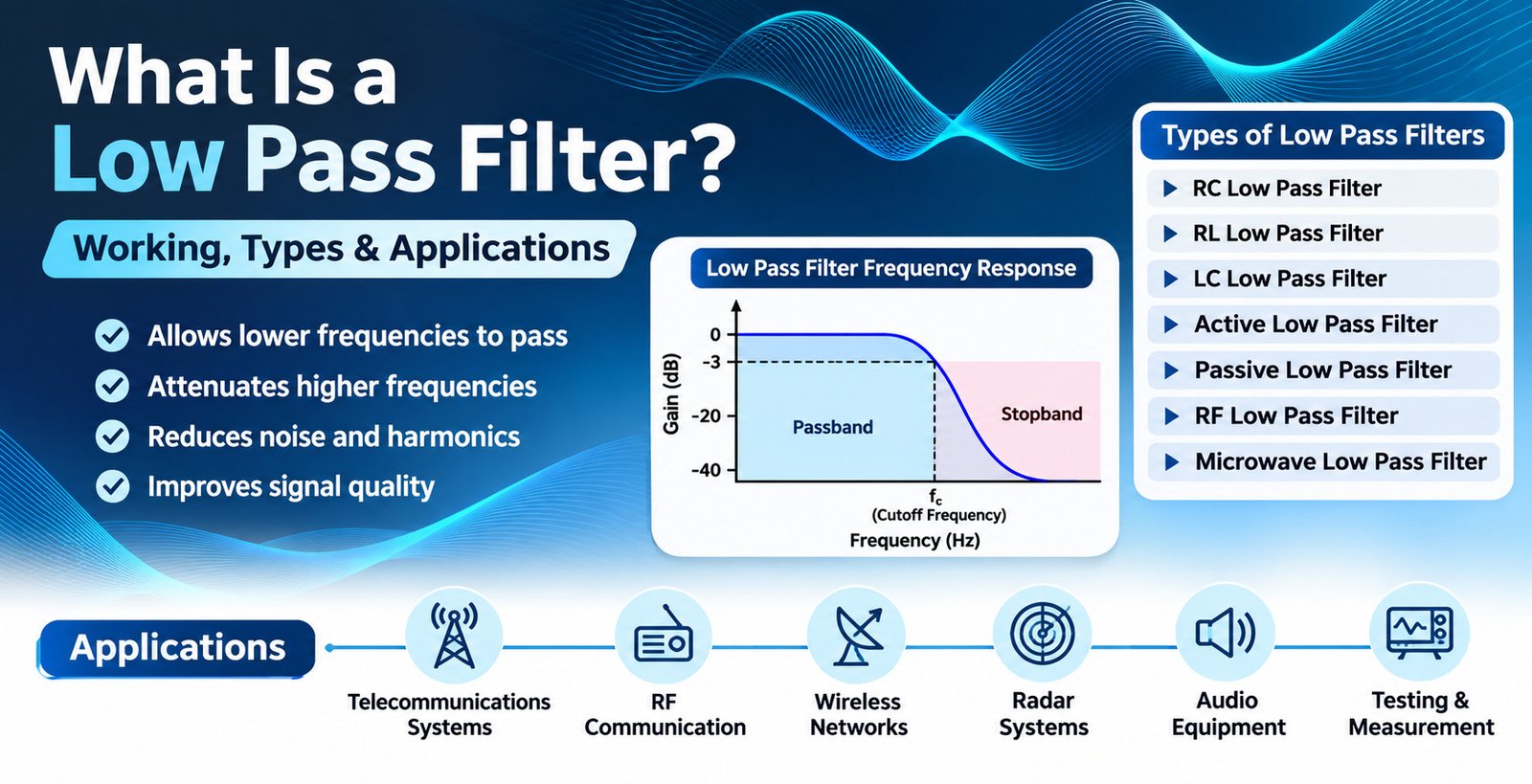
A Low Pass Filter is a frequency-selective electronic filter that allows low-frequency signals to pass through with minimal attenuation while reducing the amplitude of signals above a defined cutoff frequency.
The cutoff frequency is the point at which the output signal power drops to approximately half of its passband value, corresponding to a voltage amplitude reduction of approximately 3 dB.
For example, consider an RF low pass filter with a cutoff frequency of 1 GHz. Ideally, signals below 1 GHz pass through the filter with minimal loss, while signals above 1 GHz experience increasing attenuation.
However, practical filters do not provide an abrupt transition between the passband and stopband. Instead, attenuation increases progressively depending on the filter design, topology, and order.
Low pass filters are available in different configurations, including passive filters, active filters, LC filters, and specialized RF and microwave filters.
How Does a Low Pass Filter Work?
The working principle of a low pass filter is based on the frequency-dependent behavior of electronic components such as resistors, capacitors, and inductors.
These components interact differently with electrical signals depending on their operating frequency.
In a basic RC low pass filter, a resistor and capacitor are connected to create a frequency-dependent circuit. The resistor controls the current flow, while the capacitor provides a frequency-dependent path for signals.
At lower frequencies, the capacitor offers relatively high reactance, allowing most of the input signal to appear at the output. At higher frequencies, capacitor reactance decreases, allowing more of the high-frequency signal to pass through the capacitor to ground.
As a result, high-frequency components are attenuated while lower-frequency signals are maintained.
For RF and microwave applications, low pass filters may use carefully designed LC networks, transmission-line structures, or cavity-based configurations to achieve the required frequency response.
Low Pass Filter Working Principle
The operation of a low pass filter can be understood through three frequency regions:
1. Passband
The passband is the frequency range below the cutoff frequency. Signals within this range pass through the filter with relatively low insertion loss.
2. Cutoff Frequency
The cutoff frequency represents the transition point between the passband and stopband. It is generally defined at the -3 dB point for standard filter responses.
3. Stopband
The stopband is the frequency range above the cutoff frequency, where the filter significantly attenuates unwanted signals.
The attenuation characteristics depend on the filter order and design.
Low Pass Filter Frequency Response
A low pass filter frequency response illustrates how signal transmission changes as the input frequency increases.
- Low frequencies: Signals pass with minimal attenuation.
- Cutoff frequency: Signal amplitude reaches approximately 70.7% of its passband voltage level.
- Higher frequencies: Signal attenuation increases.
- Stopband: Unwanted high-frequency signals are significantly suppressed.
This frequency-selective behavior makes RF low pass filters useful for controlling unwanted frequency components in communication and electronic systems.
Mathematical Formula of a Low Pass Filter
The cutoff frequency of a basic RC low pass filter can be calculated using the following formula:
\[ f_c = \frac{1}{2\pi RC} \]
Where:
- \(f_c\) = Cutoff frequency in Hertz (Hz)
- \(R\) = Resistance in Ohms (Ω)
- \(C\) = Capacitance in Farads (F)
- \(\pi\) = Mathematical constant approximately equal to 3.1416
For example, if a circuit uses a 1 kΩ resistor and a 159 nF capacitor, the approximate cutoff frequency is:
\[ f_c = \frac{1}{2\pi \times 1000 \times 159 \times 10^{-9}} \]
\[ f_c \approx 1\,kHz \]
This formula is commonly used for basic first-order RC low pass filters. RF and microwave filter designs require additional considerations, including impedance matching, component parasitics, transmission-line effects, and operating frequency.
Types of Low Pass Filters
Low pass filters are available in several designs depending on frequency requirements, circuit complexity, signal characteristics, and application environments.
The most common types include:
1. RC Low Pass Filter
An RC low pass filter uses a resistor and capacitor to attenuate high-frequency signals.
It is one of the simplest filter configurations and is commonly used in audio circuits, signal conditioning, and low-frequency electronic applications.
Key Features:
- Simple circuit design.
- Low manufacturing cost.
- Easy implementation.
- Suitable for low-frequency signal filtering.
- Commonly used in basic electronic circuits.
2. RL Low Pass Filter
An RL low pass filter consists of a resistor and an inductor. It uses the frequency-dependent inductive reactance to control signal transmission.
As frequency increases, inductive reactance also increases, resulting in greater attenuation of higher-frequency signals in an appropriate circuit configuration.
Key Features:
- Uses resistor and inductor components.
- Suitable for specific power and signal applications.
- Provides frequency-dependent filtering.
- Used in electrical and electronic circuits.
3. LC Low Pass Filter
An LC low pass filter uses inductors and capacitors to provide frequency-selective filtering.
These filters are particularly useful in RF circuits because they can operate at higher frequencies and provide better selectivity than many basic RC configurations.
Key Features:
- Uses inductors and capacitors.
- Suitable for RF applications.
- Provides effective high-frequency attenuation.
- Can be designed for specific cutoff frequencies.
- Commonly used in communication and electronic equipment.
4. Active Low Pass Filter
An active low pass filter uses active components such as operational amplifiers along with resistors and capacitors.
Unlike passive filters, active filters can provide signal amplification and buffering.
Key Features:
- Can provide voltage gain.
- Offers flexible circuit design.
- Does not require inductors in many common configurations.
- Used in audio systems and signal-processing equipment.
5. Passive Low Pass Filter
A passive low pass filter uses passive components such as resistors, capacitors, and inductors without requiring an external power supply for filtering operation.
These filters are commonly used in RF systems, microwave circuits, and electronic applications where signal attenuation and frequency selection are required.
Key Features:
- No external power supply required for filtering.
- Simple and reliable design.
- Suitable for RF and microwave applications.
- Available in different frequency configurations.
6. RF Low Pass Filter
An RF low pass filter is specifically designed to operate within radio frequency ranges. It allows the required lower-frequency RF signals to pass while attenuating unwanted higher-frequency signals.
RF low pass filters are important components in wireless communication equipment, transmitters, receivers, antenna systems, and RF testing instruments.
Key Features:
- Designed for radio frequency applications.
- Helps suppress unwanted harmonics.
- Supports frequency-selective signal transmission.
- Can be designed for specific impedance requirements, commonly 50 Ohms.
- Available in different RF connector and mounting configurations.
7. Microwave Low Pass Filter
Microwave low pass filters are designed for high-frequency microwave applications where precise frequency control and low signal loss are essential.
They are used in advanced communication equipment, microwave links, radar systems, satellite communication, and RF test setups.
Key Features:
- Designed for microwave frequency ranges.
- Provides controlled passband and stopband characteristics.
- Supports high-frequency signal processing.
- Requires careful impedance and electromagnetic design.
Important Specifications of Low Pass Filters
Selecting the correct low pass filter requires understanding its electrical and mechanical specifications. These parameters determine whether the filter is suitable for a particular RF, microwave, or electronic application.
1. Cutoff Frequency
The cutoff frequency is the frequency at which the filter begins transitioning from the passband to the stopband.
It is one of the most important parameters when selecting a low pass filter.
2. Insertion Loss
Insertion loss refers to the reduction in signal power caused by inserting the filter into a transmission path.
Lower insertion loss is generally preferred because it helps maintain signal strength.
3. Return Loss
Return loss measures how effectively the filter matches the system impedance and minimizes reflected signals.
A higher return loss generally indicates better impedance matching.
4. Stopband Attenuation
Stopband attenuation indicates how effectively the filter suppresses unwanted signals above its cutoff frequency.
Higher attenuation is important when unwanted harmonics or interference need to be reduced.
5. Operating Frequency Range
The operating frequency range specifies the frequency limits within which the filter is designed to function according to its stated performance specifications.
6. Impedance
Impedance is an important consideration in RF and microwave filter applications.
Many RF systems use a standard impedance of 50 Ohms. Selecting a filter with the correct impedance helps minimize signal reflections and maintain system performance.
7. Power Handling Capacity
Power handling capacity defines the maximum RF power that a filter can safely handle under specified operating conditions.
It is particularly important in transmitter applications and high-power communication systems.
8. Connector Type
RF low pass filters may be available with different connector interfaces, depending on the application and operating frequency.
Common RF connector options include SMA, N-Type, BNC, TNC, and other specialized interfaces.
The connector should be selected according to frequency, power, mechanical compatibility, and installation requirements.
Applications of Low Pass Filters
Low pass filters are used across several industries where controlling signal frequency and reducing unwanted high-frequency components are essential.
1. Telecommunications Systems
In telecommunications infrastructure, low pass filters help control signal frequencies and reduce unwanted high-frequency interference.
They can be integrated into communication equipment, RF transmission systems, and wireless infrastructure to support reliable signal operation.
2. RF Communication Systems
RF low pass filters are widely used in radio communication equipment to suppress unwanted harmonics and high-frequency components.
They help maintain signal quality in transmitters, receivers, and other RF communication devices.
3. Wireless Communication Networks
Wireless communication systems operate across specific frequency bands. Low pass filters help manage unwanted frequency components and support the required signal characteristics.
They are used in various wireless infrastructure applications, including base stations and RF equipment.
4. Antenna Systems
Low pass filters can be integrated into antenna feed networks and RF signal paths to suppress unwanted high-frequency signals.
They help maintain the desired frequency characteristics of antenna systems.
5. Microwave Communication
Microwave low pass filters are used in high-frequency communication systems where frequency selection and unwanted signal suppression are important.
Typical applications include satellite communication, microwave links, and advanced wireless systems.
6. Radar Systems
Radar equipment requires accurate frequency control and reliable RF signal processing.
Low pass filters can be used in supporting RF circuits to reduce unwanted high-frequency components and improve signal conditioning.
7. Audio Equipment
In audio applications, low pass filters allow lower-frequency audio signals to pass while attenuating higher-frequency components.
They are commonly used in subwoofer circuits, audio crossovers, and sound-processing systems.
8. Electronic Testing and Measurement Equipment
RF test equipment and measurement instruments use frequency-selective circuits to control unwanted signals and improve measurement conditions.
Low pass filters can be integrated into signal-processing paths and laboratory testing setups.
Advantages of Using Low Pass Filters
Low pass filters offer several benefits in electronic and communication systems.
1. High-Frequency Noise Reduction: They help suppress unwanted high-frequency noise and interference.
2. Harmonic Suppression: RF low pass filters can reduce unwanted harmonics generated by transmitters and other electronic circuits.
3. Improved Signal Quality: By attenuating unwanted frequency components, they help maintain the desired signal characteristics.
4. Frequency Selection: They allow designers to define a frequency range for signal transmission.
5. System Protection: Properly designed filters can help prevent unwanted frequency components from entering sensitive circuit stages.
6. Reliable RF Performance: High-quality RF filters support stable signal transmission and effective frequency management.
7. Wide Application Compatibility: Low pass filters are available for audio, electronic, RF, microwave, and communication applications.
Difference Between Low Pass Filter and High Pass Filter
Low pass filters and high pass filters are both frequency-selective electronic components, but they perform opposite functions.
| Parameter | Low Pass Filter | High Pass Filter |
|---|---|---|
| Main Function | Allows lower frequencies to pass | Allows higher frequencies to pass |
| Signal Attenuation | Attenuates frequencies above cutoff | Attenuates frequencies below cutoff |
| Frequency Selection | Low-frequency signals | High-frequency signals |
| Common Applications | RF harmonic suppression, audio filtering | DC blocking, high-frequency signal selection |
| Frequency Response | Decreases at higher frequencies | Increases at higher frequencies |
The choice between a low pass filter and a high pass filter depends on the required frequency range and the characteristics of the application.
Difference Between Low Pass Filter and Band Pass Filter
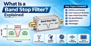
A low pass filter allows frequencies below its cutoff frequency to pass, whereas a band pass filter allows signals within a specified frequency range to pass.
| Parameter | Low Pass Filter | Band Pass Filter |
|---|---|---|
| Frequency Range | Below cutoff frequency | Between lower and upper cutoff frequencies |
| Main Purpose | Suppress higher frequencies | Select a specific frequency band |
| Passband | Starts from low frequencies | Defined frequency range |
| Applications | Harmonic suppression, noise filtering | Wireless communication, RF receivers |
Both filters are widely used in RF and microwave engineering for frequency management.
How to Choose the Right RF Low Pass Filter?
Choosing the correct RF low pass filter is essential for achieving the desired electrical performance and reliable operation.
Before selecting a filter, consider the following factors:
1. Required Cutoff Frequency: Determine the maximum frequency that needs to pass through the filter.
2. Operating Frequency Range: Ensure the filter supports the required frequency range of your application.
3. Insertion Loss: Select a filter with suitable insertion loss to minimize unwanted signal reduction.
4. Stopband Attenuation: Check the attenuation level required to suppress unwanted harmonics and interference.
5. Impedance Matching: Confirm that the filter impedance matches the RF system, commonly 50 Ohms.
6. Power Requirements: Check the maximum input power and operating conditions.
7. Connector Compatibility: Select the correct RF connector interface for easy integration into the existing system.
8. Environmental Conditions: Consider operating temperature, humidity, vibration, and installation requirements.
9. Mechanical Configuration: Check mounting dimensions, housing material, and installation arrangements.
Evaluating these parameters helps engineers select suitable low pass filters for specific RF, telecom, and microwave applications.
Role of Low Pass Filters in Modern RF and Telecom Infrastructure
The demand for reliable wireless communication and high-performance RF systems continues to increase. Modern telecom infrastructure requires precise signal management to maintain communication quality and minimize unwanted frequency components.
Low pass filters support these requirements by providing frequency-selective filtering in RF transmission and reception paths.
In RF transmitters, low pass filters are particularly useful for suppressing unwanted harmonic frequencies generated during signal amplification. This helps control out-of-band emissions and supports compliance with applicable system requirements.
In wireless infrastructure, these filters can be integrated into RF modules, antenna systems, and communication equipment to achieve the required frequency response.
As communication technologies continue to develop, the importance of properly designed RF and microwave filtering solutions remains significant.
Why Quality Matters When Selecting Low Pass Filters
The performance of an RF low pass filter directly affects the characteristics of the overall RF system.
A poorly selected filter may introduce excessive insertion loss, impedance mismatch, insufficient stopband attenuation, or unwanted variations in frequency response.
For this reason, engineers and system integrators should evaluate the filter’s electrical specifications, mechanical design, connector quality, and operating conditions before procurement.
Selecting a reliable RF filtering solution helps maintain consistent performance, improve signal management, and support the long-term reliability of communication infrastructure.
Frequently Asked Questions About Low Pass Filters
1. What is a low pass filter?
A low pass filter is an electronic circuit or component that allows signals below a specified cutoff frequency to pass while attenuating signals above that frequency.
2. What is the main purpose of a low pass filter?
The main purpose of a low pass filter is to suppress unwanted high-frequency signals, reduce noise, and maintain the desired lower-frequency signal components.
3. What is the cutoff frequency of a low pass filter?
The cutoff frequency is the frequency at which the output signal power decreases by approximately 3 dB compared with its passband level.
4. What are the different types of low pass filters?
Common types include RC low pass filters, RL low pass filters, LC low pass filters, active low pass filters, passive low pass filters, RF low pass filters, and microwave low pass filters.
5. What is an RF low pass filter?
An RF low pass filter is designed to allow signals below a specified RF cutoff frequency to pass while attenuating unwanted higher-frequency signals and harmonics.
6. Where are low pass filters used?
Low pass filters are used in telecommunications, wireless communication systems, RF transmitters, antenna networks, microwave equipment, radar systems, audio equipment, and electronic testing instruments.
7. Why are low pass filters used in RF transmitters?
They are commonly used in RF transmitters to suppress unwanted harmonic frequencies and reduce out-of-band emissions.
8. What is the difference between an active and passive low pass filter?
An active low pass filter uses active components, such as operational amplifiers, and can provide signal amplification. A passive low pass filter uses resistors, capacitors, and inductors without requiring an external power supply for its filtering function.
9. What is the difference between a low pass filter and a high pass filter?
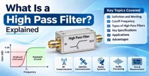
A low pass filter allows lower frequencies to pass and attenuates higher frequencies. A high pass filter does the opposite by allowing higher frequencies to pass while attenuating lower frequencies.
10. How do I select the right RF low pass filter?
Consider cutoff frequency, operating frequency range, insertion loss, return loss, stopband attenuation, impedance, power handling capacity, connector type, and environmental requirements.
Conclusion
Low pass filters are essential components in modern electronic, RF, microwave, and telecommunications systems. By allowing desired lower-frequency signals to pass while attenuating unwanted higher-frequency components, they help improve signal quality, reduce interference, and control harmonic emissions.
From basic RC and LC circuits to advanced RF and microwave filtering solutions, low pass filters are available in different configurations to meet diverse engineering requirements.
For telecom infrastructure providers, RF engineers, equipment manufacturers, and system integrators, selecting the right low pass filter requires careful evaluation of electrical specifications, frequency response, impedance, power handling, and mechanical compatibility.
SRFS Teleinfra provides RF and telecom infrastructure solutions designed to support diverse communication and engineering requirements. Explore the low pass filter product range and related RF components at SRFS Teleinfra – Low Pass Filters.