
Bias Tees
Bias Tees are essential RF and microwave components designed to combine a DC voltage or current with an RF signal on a single transmission line. They allow DC power to be supplied to active RF devices while the same coaxial cable carries the RF signal. This makes Bias Tees useful for powering active antennas, low-noise amplifiers (LNAs), RF amplifiers, and other electronic devices without requiring a separate DC power cable.
At SRFS Teleinfra, Bias Tees are intended for applications that require dependable RF signal transmission and DC power injection. Depending on the selected model, they can support different frequency ranges, connector interfaces, DC voltage and current ratings, and RF power levels. These components are widely used in wireless communication, telecom infrastructure, RF laboratories, antenna systems, microwave testing, and aerospace and defense electronics.
A suitable Bias Tee helps maintain RF signal integrity while isolating the DC supply from the RF-only port. The correct model should be selected according to the operating frequency, insertion loss, isolation, impedance, RF power, DC voltage, and current requirements of the application.
What Is a Bias Tee?
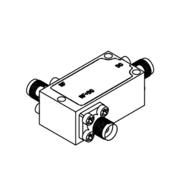
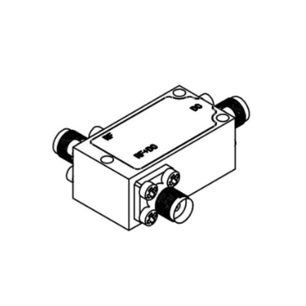
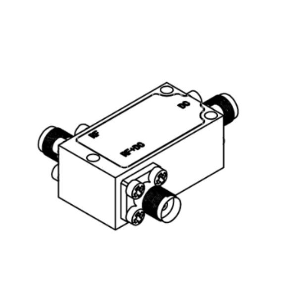
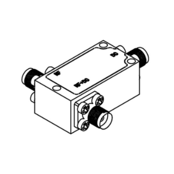
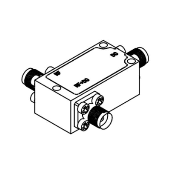
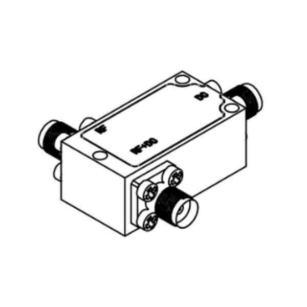
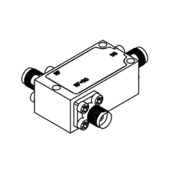
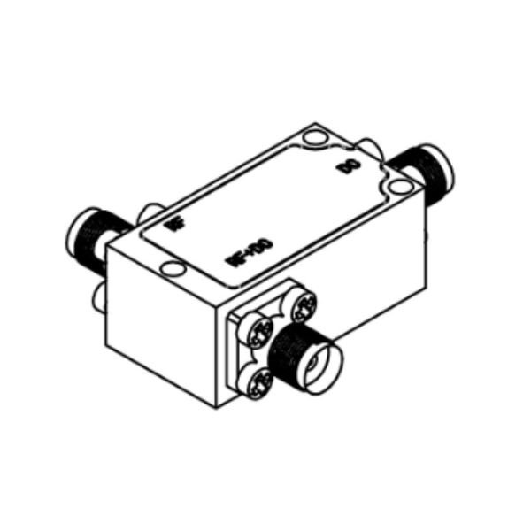
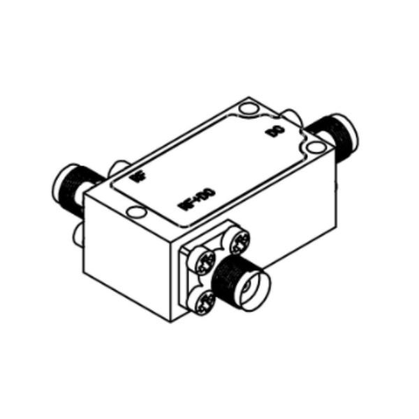
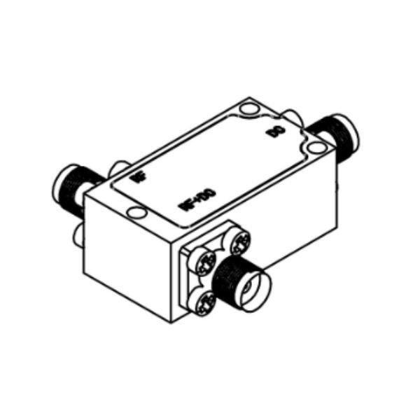
A Bias Tee, also called an RF Bias Tee or Bias-T, is a three-port passive component that combines DC power and an RF signal onto a common output line, or separates them when used in an appropriate configuration.
Its three main ports are:
RF Port: Passes the RF signal while blocking DC.
DC Port: Supplies DC voltage or current while providing RF isolation.
RF + DC Port: Carries the combined RF signal and DC supply to the connected device.
Internally, a Bias Tee typically uses a capacitor in the RF path to block DC and an inductor or RF choke in the DC path to restrict RF energy from entering the DC supply. This arrangement enables RF transmission and DC power delivery through the same cable.
Types of Bias Tees
1. Broadband RF Bias Tee
Designed to combine DC power and RF signals across a broad frequency range. Suitable for wireless communication, RF testing, and general-purpose microwave systems.
2. High-Frequency Bias Tee
Engineered for high-frequency RF and microwave applications where low insertion loss and reliable isolation are essential. Available frequency limits depend on the specific design and connector interface.
3. High-Power Bias Tee
Designed for applications requiring higher RF power handling. Selection depends on average and peak RF power, thermal performance, and the DC operating limits.
4. High-Current Bias Tee
Suitable for powering active devices that require higher DC current through a shared RF transmission line. Maximum current depends on the model and its internal components.
5. Wideband Microwave Bias Tee
Designed for broadband microwave measurements, active-device characterization, and laboratory testing across a specified frequency range.
6. Custom RF Bias Tee
Custom configurations may be selected according to the required frequency range, connector type, DC voltage, current capacity, RF power rating, and mechanical dimensions.
Technical Specifications
Bias Tee specifications vary by model. The following parameters should be considered when selecting a suitable product.
Parameter | Description |
|---|---|
Component Type | RF Bias Tee / Bias-T |
Impedance | Typically 50 Ohm for RF systems |
Frequency Range | Model-dependent |
Insertion Loss | Depends on frequency and design |
Return Loss / VSWR | Model-dependent |
DC Voltage | According to model rating |
DC Current | According to model rating |
RF Power Handling | Depends on model and operating conditions |
DC-to-RF Isolation | Model-dependent |
RF Connector Interface | SMA, N-Type or other compatible interfaces, subject to availability |
DC Port | Connector or terminal configuration, depending on model |
Applications | RF testing, telecom, antenna systems, microwave and active-device biasing |
Important: Confirm the exact operating frequency, voltage, current, isolation, and RF power ratings against the selected model’s datasheet before ordering. These values should not be assumed to be identical across all Bias Tees.
Applications of Bias Tees
Bias Tees are commonly used in the following applications:
Telecom and wireless communication infrastructure
Active antennas and antenna amplifiers
Low-noise amplifiers (LNAs)
RF and microwave test setups
Vector Network Analyzer (VNA) measurements
RF amplifier testing and characterization
Satellite communication systems
Radar and aerospace electronics
Defense communication equipment
Laboratory research and development
Semiconductor and active-device testing
Remote powering of RF components
Key Features of Bias Tees
Combines DC power and RF signals on a single coaxial line
Enables remote powering of compatible active RF devices
Helps isolate DC from the RF-only port
Supports a range of frequency bands, depending on model
Available with different connector configurations
Designed for RF signal transmission with controlled insertion loss
Available in different DC voltage and current ratings
Useful for compact RF test setups and communication installations
Simplifies cabling where RF and DC share the same transmission path
Bias Tees Product Specifications
| Product Type | Impedance | Frequency Range | Application |
|---|---|---|---|
| Broadband RF Bias Tee | Typically 50 Ohm | Model-dependent | Broadband RF Systems |
| High-Frequency Bias Tee | Typically 50 Ohm | Model-dependent | Microwave Testing |
| High-Power Bias Tee | Typically 50 Ohm | Model-dependent | RF Power Applications |
| High-Current Bias Tee | Typically 50 Ohm | Model-dependent | Active RF Device Powering |
| Wideband Microwave Bias Tee | Typically 50 Ohm | Model-dependent | RF Laboratory Measurements |
| SMA Bias Tee | Typically 50 Ohm | Model-dependent | RF Test Equipment |
| N-Type Bias Tee | Typically 50 Ohm | Model-dependent | Telecom and Antenna Systems |
| Low-Loss Bias Tee | Typically 50 Ohm | Model-dependent | Signal Transmission |
| Precision RF Bias Tee | Typically 50 Ohm | Model-dependent | RF Calibration and Testing |
| Custom RF Bias Tee | As Specified | As Required | Application-Specific RF Systems |
Why Choose us
RF Component Solutions
SRFS Teleinfra serves RF, microwave, wireless communication, and telecom infrastructure requirements with components for signal transmission and system integration.
Application-Based Selection
Choose a Bias Tee according to your frequency band, RF power, DC voltage, current requirements, and connector configuration.
Multiple Configuration Requirements
Depending on availability and product requirements, connector interfaces and electrical configurations can be evaluated for specific applications.
Technical Support
Share your operating frequency, DC voltage, current, RF power, and connector requirements to help identify a suitable Bias Tee configuration for your system.
Frequently Asked Questions
A Bias Tee combines DC power with an RF signal so that a compatible active device can receive power and an RF signal through the same coaxial cable.
It typically uses a capacitor in the RF path to block DC and an inductor or RF choke in the DC path to limit RF leakage into the power supply.
The three ports are RF, DC, and RF + DC. The RF + DC port carries the combined signal and power to the connected device.
Most RF Bias Tees designed for standard coaxial RF systems use 50 Ohm impedance.
The frequency range depends on its design. Different products cover different bands, from lower-frequency RF applications to high-frequency microwave systems.
Yes. A compatible Bias Tee can supply DC power to an active antenna or antenna-mounted amplifier through the coaxial feed, provided the voltage, current, and port arrangement are suitable.
A Bias Tee combines or separates DC and RF signals. A DC Block primarily prevents DC from passing through a specified RF path while allowing RF signals to pass.
Provide the operating frequency range, DC voltage, required current, RF power level, and connector configuration so the appropriate product can be identified.