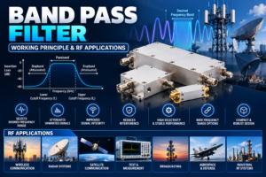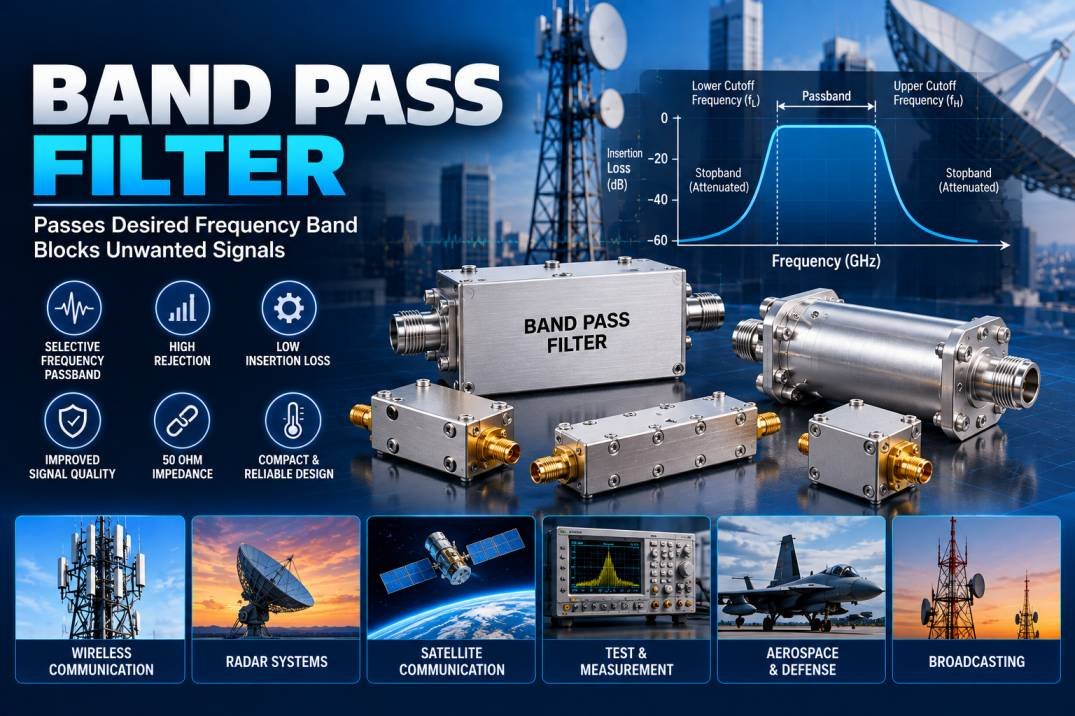
A Band Pass Filter is an RF and electronic filtering device designed to allow signals within a specific frequency range to pass while attenuating frequencies below and above that range. It is widely used in wireless communication, RF systems, radar, satellite communication, test equipment, broadcasting, and electronic instrumentation.
By controlling the desired frequency band, a Band Pass Filter helps reduce unwanted signals, interference, and out-of-band noise while improving the overall performance and signal quality of an RF system.
What Is a Band Pass Filter?
A Band Pass Filter is a frequency-selective circuit or RF component that passes frequencies between a defined lower cutoff frequency and upper cutoff frequency.
The frequency range between these two cutoff points is called the passband. Frequencies outside the passband are progressively attenuated.
For example, a filter designed to operate from 2.4 GHz to 2.5 GHz allows signals within this range to pass while reducing signals below 2.4 GHz and above 2.5 GHz.
The main parameters used to describe a Band Pass Filter include center frequency, bandwidth, insertion loss, return loss, rejection, and VSWR.
How Does a Band Pass Filter Work?
The working principle of a Band Pass Filter is based on frequency-selective signal transmission. The filter is designed so that its internal electrical structure provides a low-loss path for the desired frequency range while creating greater attenuation outside that range.
A typical Band Pass Filter has three important frequency points:
- Lower Cutoff Frequency: The lower edge of the passband.
- Center Frequency: The frequency around which the filter is optimized.
- Upper Cutoff Frequency: The upper edge of the passband.
The difference between the upper and lower cutoff frequencies defines the bandwidth:
Bandwidth = Upper Cutoff Frequency − Lower Cutoff Frequency
The filter’s response gradually changes from the passband to the stopband. The sharpness of this transition depends on the filter design and order.
Key Features of Band Pass Filter
A Band Pass Filter provides several important features for RF and microwave systems:
Defined Frequency Passband
It allows a specific frequency range to pass while suppressing unwanted frequencies outside the operating band.
High Out-of-Band Rejection
A properly designed filter can significantly attenuate unwanted signals outside the passband, helping reduce interference.
Low Insertion Loss
Low insertion loss is important because excessive signal attenuation can reduce system efficiency and available signal power.
Good Return Loss
A good return loss indicates better impedance matching between the filter and connected RF components.
Compact RF Design
Depending on frequency and technology, Band Pass Filters can be manufactured in compact forms suitable for integrated RF equipment and communication systems.
High Frequency Stability
Quality RF filters are designed to maintain their electrical characteristics across their specified operating conditions.
Important Specifications of Band Pass Filter
Selecting the correct Band Pass Filter requires understanding its major technical specifications.
| Parameter | Description |
|---|---|
| Center Frequency | Frequency at the center of the passband |
| Passband | Frequency range allowed to pass |
| Bandwidth | Difference between upper and lower cutoff frequencies |
| Insertion Loss | Signal loss through the filter |
| Return Loss | Measure of reflected signal power |
| VSWR | Indicates impedance matching |
| Rejection | Attenuation outside the passband |
| Impedance | Commonly 50 Ohms in RF systems |
| Power Handling | Maximum RF power the filter can handle |
Actual specifications vary according to the filter design, frequency range, construction, and manufacturer.
Types of Band Pass Filter
Different technologies can be used to create Band Pass Filters depending on frequency and application requirements.
LC Band Pass Filter
LC filters use inductors and capacitors to create frequency-selective characteristics. They are commonly used in electronic and lower-frequency RF circuits.
Cavity Band Pass Filter
Cavity filters use resonant metallic structures and are widely used in RF and microwave applications where high selectivity and strong rejection are required.
Ceramic Band Pass Filter
Ceramic filters use dielectric resonators and can provide compact designs with useful RF performance.
SAW Band Pass Filter
Surface Acoustic Wave filters are commonly used in compact wireless and communication equipment where precise frequency filtering is required.
Waveguide Band Pass Filter
Waveguide filters are used at microwave and higher-frequency ranges, particularly in radar, satellite, and high-power RF systems.
Applications of Band Pass Filter
Wireless Communication
Band Pass Filters are widely used in cellular, Wi-Fi, radio, and other wireless communication systems to isolate required frequency channels and reduce interference.
RF and Microwave Systems
They are used in RF front ends, receivers, transmitters, amplifiers, signal-processing equipment, and microwave communication systems.
Radar Systems
Radar equipment uses frequency-selective filtering to separate desired signals from unwanted interference and noise.
Satellite Communication
Band Pass Filters help control RF channels in satellite communication systems and support efficient frequency management.
Test and Measurement
RF test equipment uses filters to isolate specific frequency ranges during signal analysis, measurement, and testing.
Broadcasting
Radio and television broadcasting systems use frequency-selective filters to manage channels and suppress unwanted emissions.
Aerospace and Defense
RF filtering is important in aerospace and defense electronics where systems may operate in complex electromagnetic environments.
Advantages of Using a Band Pass Filter
A Band Pass Filter can improve RF system performance by restricting the signal path to the required frequency range. It helps reduce unwanted interference, suppress out-of-band signals, improve receiver selectivity, and protect sensitive RF components from undesired signals.
For communication systems operating in crowded frequency environments, appropriate filtering can be particularly important for maintaining signal integrity and reliable system operation.
How to Select the Right Band Pass Filter
When selecting a Band Pass Filter, consider the following factors:
- Determine the required center frequency.
- Define the lower and upper cutoff frequencies.
- Calculate the required bandwidth.
- Check insertion loss across the passband.
- Verify return loss and VSWR.
- Check out-of-band rejection requirements.
- Confirm RF power-handling capability.
- Select the appropriate connector and mounting configuration.
- Consider operating temperature and environmental requirements.
- Verify compatibility with the complete RF system.
Conclusion
A Band Pass Filter is an essential RF component for controlling frequency transmission and suppressing unwanted signals. By allowing a defined frequency range to pass while attenuating frequencies outside the passband, it helps improve selectivity, reduce interference, and maintain signal integrity.
From wireless communication and radar to satellite systems, broadcasting, aerospace, defense, and RF test equipment, Band Pass Filters provide an effective method for managing frequency-dependent signals. Proper selection requires careful consideration of center frequency, bandwidth, insertion loss, return loss, rejection, VSWR, power handling, and environmental conditions.
FAQs About Band Pass Filter
1. What is a Band Pass Filter?
A Band Pass Filter is an RF or electronic filter that allows signals within a specific frequency range to pass while attenuating frequencies outside that range.
2. What is the bandwidth of a Band Pass Filter?
Bandwidth is the difference between the upper and lower cutoff frequencies of the filter.
3. What is center frequency?
Center frequency is the frequency around which the Band Pass Filter is primarily designed to operate.
4. Where are Band Pass Filters used?
They are used in wireless communication, radar, satellite communication, broadcasting, RF test equipment, aerospace, defense, and microwave systems.
5. Why is insertion loss important?
Insertion loss indicates how much signal power is lost when the signal passes through the filter. Lower insertion loss is generally desirable for efficient RF transmission.
6. What is out-of-band rejection?
Out-of-band rejection refers to the filter’s ability to attenuate frequencies outside its specified passband.
7. Are Band Pass Filters used in 50-ohm RF systems?
Yes. Many RF and microwave Band Pass Filters are designed for 50-ohm systems, although the exact impedance should always be verified from the product specifications.
8. How do I choose a Band Pass Filter?
Consider center frequency, bandwidth, insertion loss, return loss, rejection, VSWR, power handling, connectors, environmental conditions, and system requirements.