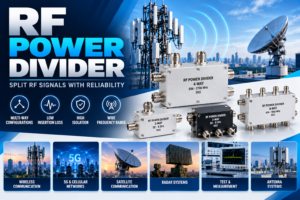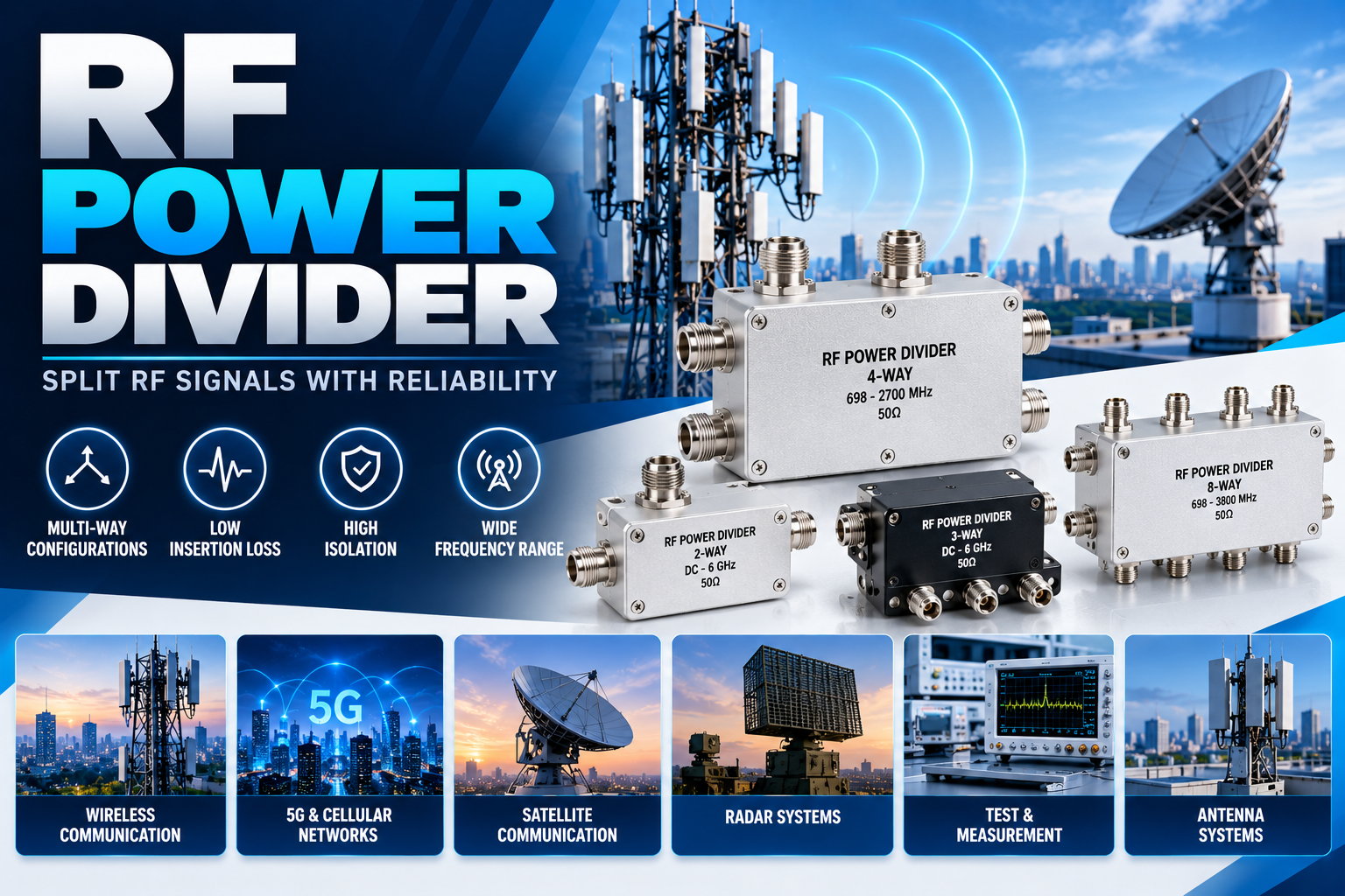
An RF Power Divider is a passive RF and microwave component used to split one input signal into two or more output signals while maintaining controlled impedance and predictable electrical performance. RF power dividers are widely used in wireless communication, 5G networks, radar, satellite communication, test and measurement, antenna systems, broadcasting, and other high-frequency applications.
Unlike a simple electrical junction, a properly designed RF Power Divider provides controlled signal distribution, impedance matching, isolation between ports in certain configurations, and predictable insertion loss. These characteristics make power dividers important wherever an RF signal needs to be distributed to multiple circuits or antennas.
What Is an RF Power Divider?
An RF Power Divider is a passive device that takes RF power at a single input port and distributes it among multiple output ports. Depending on its design, the output power can be divided equally or according to a specified ratio.
For example, a 2-way RF Power Divider can divide an incoming RF signal into two output signals. An ideal equal 2-way divider would distribute approximately half of the input power to each output, excluding practical losses.
Power dividers are available in several configurations, including 2-way, 3-way, 4-way, 6-way, 8-way, and higher-port-count versions.
How Does an RF Power Divider Work?
The basic operating principle of an RF Power Divider is controlled electromagnetic signal distribution.
When an RF signal enters the input port, the internal transmission-line or circuit structure divides the signal energy between the output ports. The design determines how much power reaches each output and how well the ports are matched.
For an ideal equal 2-way divider:
Input Power → Output 1 + Output 2
If 100% of the input power could be distributed without losses, each output would theoretically receive 50% of the available power. In real-world components, some power is lost because of conductor loss, dielectric loss, mismatch, and other design factors.
The actual output level is therefore determined by the division ratio and insertion loss of the device.
Main Types of RF Power Divider
Different RF systems require different power distribution configurations. Common types include:
2-Way RF Power Divider
A 2-way divider has one input and two outputs. It is one of the most commonly used configurations for distributing RF signals between two circuits, antennas, amplifiers, or measurement paths.
3-Way RF Power Divider
A 3-way divider distributes an input signal among three output ports. It can be designed for equal or unequal power distribution depending on system requirements.
4-Way RF Power Divider
A 4-way RF Power Divider distributes an input signal into four outputs. It is frequently used in antenna arrays, communication systems, RF distribution networks, and test equipment.
Multi-Way RF Power Divider
Higher-port-count dividers can distribute one RF signal across several outputs. These are useful in large antenna systems, cellular infrastructure, distributed RF networks, and signal routing applications.
Resistive vs Wilkinson Power Divider
Two important power-divider technologies are resistive and Wilkinson designs.
Resistive Power Divider
A resistive divider uses resistive elements to distribute RF power. It can provide a compact and relatively simple solution, but power dissipation in the resistors contributes to insertion loss.
Wilkinson Power Divider
A Wilkinson power divider uses transmission-line structures and isolation resistors to achieve power division with good impedance matching and output-port isolation.
Wilkinson designs are widely used when low insertion loss, good isolation, and controlled RF performance are required.
Key Specifications of an RF Power Divider
Selecting an RF Power Divider requires understanding several important specifications.
| Specification | Importance |
|---|---|
| Frequency Range | Defines the RF frequencies supported by the divider |
| Number of Ways | Determines the number of output ports |
| Division Ratio | Defines how input power is distributed |
| Insertion Loss | Indicates signal power lost through the component |
| Isolation | Indicates separation between output ports |
| VSWR | Indicates impedance matching performance |
| Return Loss | Indicates reflected signal level |
| Impedance | Common RF systems typically use 50 Ohms |
| Power Handling | Defines the maximum RF power the divider can handle |
| Connector Type | Determines system and cable compatibility |
These specifications should be evaluated according to the operating conditions of the intended RF system.
Insertion Loss and Power Division
Insertion loss is one of the most important parameters when selecting a power divider.
An ideal equal 2-way power divider has a theoretical division loss of approximately 3 dB per output. Practical insertion loss is higher because of internal component and transmission losses.
For example, if a divider has a 3 dB theoretical division loss plus additional insertion loss, the actual output power will be slightly lower than the ideal half-power level.
For multi-way dividers, theoretical division loss increases as the number of output ports increases.
RF Power Divider vs RF Power Combiner
An RF Power Divider and RF Power Combiner can have similar physical construction, but their intended functions are different.
An RF Power Divider takes one input and distributes it to multiple outputs.
An RF Power Combiner takes multiple input signals and combines them into one output.
Some RF components can operate bidirectionally, depending on their design and application, but the specified performance should always be verified before using a divider as a combiner.
Applications of RF Power Divider
RF Power Dividers are used in a wide range of communication and electronic systems.
Wireless Communication
They distribute RF signals between multiple radio circuits, antennas, or transceiver paths in wireless infrastructure.
5G and Cellular Networks
RF power distribution is important in cellular base stations and antenna systems. Power dividers can distribute signals to multiple antenna elements or RF paths.
Antenna Systems
In antenna arrays, a divider can distribute an RF signal to multiple antenna elements. Controlled amplitude and phase relationships can be important for achieving the desired antenna performance.
Test and Measurement
RF laboratories use power dividers with signal generators, spectrum analyzers, network analyzers, and other instruments to create multiple measurement paths.
Radar Systems
Radar equipment can use RF power distribution components for signal routing, antenna arrays, transmitter systems, and receiver architectures.
Satellite Communication
RF power dividers can be integrated into satellite communication equipment, ground stations, RF distribution networks, and antenna systems.
Broadcasting
Radio and broadcasting systems may use RF distribution components to route signals to multiple RF circuits or transmission paths.
Industrial and Defense Electronics
RF power dividers are also used in specialized communication equipment, electronic systems, instrumentation, and high-frequency defense applications.
Benefits of Using an RF Power Divider
An RF Power Divider provides several benefits in RF system design:
- Distributes one RF signal to multiple paths
- Supports controlled power distribution
- Available in multiple output configurations
- Can provide good impedance matching
- Wilkinson designs can provide high output isolation
- Compact options are available for space-constrained systems
- Suitable for broadband and narrowband applications
- Available with various RF connector configurations
- Supports antenna and communication system architectures
How to Select the Right RF Power Divider
Choosing the correct divider requires more than simply selecting the number of output ports.
First, determine the operating frequency range of the system. The divider must support the required frequency band.
Next, check the number of outputs and required power division ratio. An equal divider is suitable when similar power levels are required at each output, while an unequal divider can distribute different power levels.
The power handling capability is also critical. The component should safely handle the expected continuous-wave and, where applicable, peak RF power.
Other important factors include VSWR, insertion loss, isolation, connector type, physical dimensions, mounting configuration, and environmental requirements.
RF Power Divider Connectors
RF power dividers are available with different connector interfaces, including SMA, N, BNC, TNC, 2.92 mm, 3.5 mm, and other RF connector types.
The connector should match the system’s cable and equipment interface. For high-frequency applications, connector quality and mechanical precision can significantly affect overall RF performance.
Conclusion
An RF Power Divider is an essential passive component for distributing RF and microwave signals across multiple paths. From simple 2-way signal distribution to complex multi-output antenna networks, power dividers help engineers create controlled and reliable RF architectures.
When selecting an RF Power Divider, frequency range, power handling, division ratio, insertion loss, isolation, VSWR, impedance, connector type, and mechanical configuration should all be considered. Choosing the correct design helps maintain signal integrity and reliable operation across communication, antenna, radar, satellite, test, and industrial RF systems.
FAQs About RF Power Divider
1. What is an RF Power Divider?
An RF Power Divider is a passive RF component that divides one input signal into two or more output signals.
2. What is a 2-way RF Power Divider?
A 2-way divider has one input and two outputs and is commonly used to distribute an RF signal between two circuits or antennas.
3. What is the theoretical loss of a 2-way power divider?
An ideal equal 2-way divider has a theoretical power division loss of approximately 3 dB per output, before additional practical losses.
4. What is the difference between a power divider and a combiner?
A divider distributes one input signal into multiple outputs, while a combiner combines multiple input signals into one output.
5. What is a Wilkinson power divider?
A Wilkinson power divider is a transmission-line-based RF divider designed to provide controlled power division, impedance matching, and output-port isolation.
6. What impedance is commonly used for RF power dividers?
Most RF communication and microwave systems commonly use a 50-ohm impedance.
7. Where are RF Power Dividers used?
They are used in wireless communication, 5G, antenna arrays, radar, satellite communication, broadcasting, test equipment, and industrial RF systems.
8. What specifications should be checked before buying an RF Power Divider?
Important specifications include frequency range, number of ways, division ratio, insertion loss, isolation, VSWR, power handling, impedance, and connector type.
9. Can an RF Power Divider be used as a combiner?
Some divider designs can operate in the reverse direction, but the manufacturer’s specifications should be checked before using a particular device as a combiner.
10. Why is isolation important in an RF Power Divider?
Isolation helps reduce unwanted interaction between output ports and can improve the stability and performance of connected RF circuits.