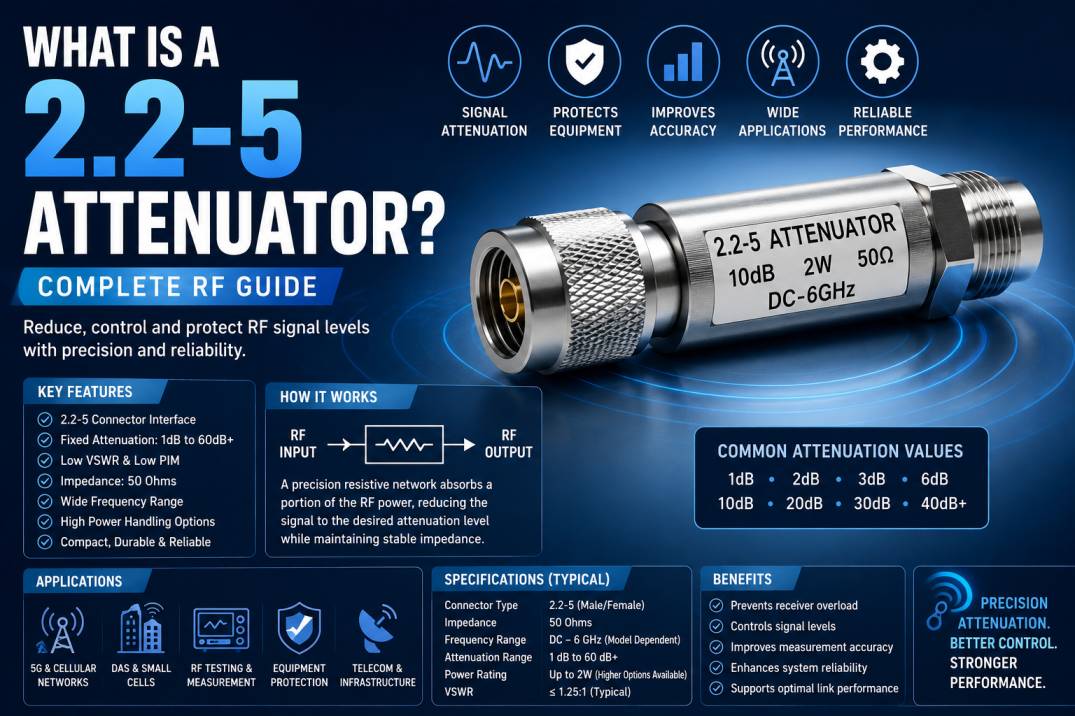
A 2.2-5 attenuator is a passive RF component used to reduce the power level of an RF or microwave signal by a specific amount while maintaining a controlled impedance and minimizing unwanted signal reflections. The 2.2-5 interface is a compact RF connector technology developed for modern wireless infrastructure and high-performance RF applications where low PIM, reliable mechanical performance, and efficient signal transmission are important.
2.2-5 attenuators are commonly available as fixed coaxial attenuators with attenuation values such as 1 dB, 2 dB, 3 dB, 6 dB, 10 dB, and higher values. Depending on the design, these components can support applications across cellular infrastructure, 5G networks, distributed antenna systems, RF testing, instrumentation, and other wireless systems.
Unlike an RF amplifier, which increases signal power, an attenuator intentionally reduces signal power. This makes it useful for preventing receiver overload, controlling signal levels, improving measurement accuracy, protecting sensitive RF equipment, and maintaining predictable signal conditions within a transmission chain.
What Is a 2.2-5 Attenuator?
A 2.2-5 attenuator is an RF fixed attenuator equipped with a 2.2-5 coaxial interface.
The term “2.2-5” refers to the connector interface rather than the attenuation value. The connector series is designed as a compact RF interconnect solution for applications requiring high-frequency performance, low passive intermodulation, and reliable mechanical connection.
A typical 2.2-5 attenuator consists of:
- 2.2-5 RF connector interface
- Resistive attenuation network
- Conductive center contact
- Dielectric support
- Conductive outer body
- Protective plating
- RF housing
The attenuation network absorbs a controlled portion of the input RF power and allows the remaining signal to continue through the transmission path.
What Does 2.2-5 Mean?
The 2.2-5 designation identifies a specific RF connector interface. It is sometimes written as 2.2/5, 2.2-5, or referred to as a 2205 interface in some product catalogs.
The connector series is intended for compact, high-performance RF applications. It is associated with wireless infrastructure applications where space efficiency, low PIM, and reliable RF performance are important.
It is important not to confuse the “2.2-5” designation with the physical dimensions of the attenuator itself or with a 2.2 dB to 5 dB attenuation range.
How Does a 2.2-5 Attenuator Work?
A 2.2-5 attenuator works by introducing a controlled amount of RF loss into a transmission path.
For example, if a signal enters a 3 dB attenuator, the output power is reduced by 3 dB, assuming the attenuator is operating within its specified frequency and power limits.
The attenuation is achieved through a carefully designed resistive network that provides a controlled loss while maintaining the desired impedance.
Basic Signal Flow
RF Source → 2.2-5 Attenuator → RF Cable → Receiver or RF Device
The attenuator can be inserted between components to reduce the signal to a more appropriate level.
Understanding RF Attenuation
Attenuation is measured in decibels (dB).
The relationship between input and output power is:
Pout = Pin × 10^(-A/10)
Where:
- Pout = Output power
- Pin = Input power
- A = Attenuation in dB
For example:
| Attenuation | Approximate Output Power |
|---|---|
| 1 dB | 79.4% |
| 2 dB | 63.1% |
| 3 dB | 50.1% |
| 6 dB | 25.1% |
| 10 dB | 10% |
| 20 dB | 1% |
| 30 dB | 0.1% |
Therefore, a 3 dB attenuator reduces the power to approximately half of the input power.
Why Use a 2.2-5 Attenuator?
A 2.2-5 attenuator can be used to control RF power levels throughout a wireless system.
Major reasons include:
- Reducing excessive signal power
- Preventing receiver overload
- Improving impedance matching
- Protecting sensitive RF equipment
- Controlling signal levels
- Improving measurement accuracy
- Simulating cable loss
- Adjusting RF link budgets
- Reducing unwanted signal reflections
- Supporting RF system testing
Main Types of 2.2-5 Attenuators
2.2-5 attenuators can be classified according to attenuation value, power rating, configuration, frequency range, and construction.
1. Fixed 2.2-5 Attenuator
A fixed attenuator provides a predetermined attenuation value.
Common values include:
- 1 dB
- 2 dB
- 3 dB
- 6 dB
- 10 dB
- 20 dB
- 30 dB
- Higher attenuation values
Commercial 2.2-5 attenuators are available in different attenuation ranges depending on the manufacturer and model. Some product families offer values from 1 dB to 60 dB.
2. High-Power 2.2-5 Attenuator
High-power attenuators are designed to dissipate greater amounts of RF energy.
Power ratings vary significantly between models. For example, commercial 2.2-5 attenuator families are available with ratings such as 2 W, while other designs can support higher power levels.
High-power attenuators require careful thermal design because the attenuated RF energy is converted primarily into heat.
3. Low-PIM 2.2-5 Attenuator
Low-PIM attenuators are designed for wireless infrastructure where passive intermodulation performance is important.
Low PIM is particularly relevant in:
- Cellular networks
- Distributed antenna systems
- Small cells
- 4G LTE infrastructure
- 5G infrastructure
- High-density wireless installations
The 2.2-5 connector platform itself has been developed with low-PIM wireless infrastructure applications in mind.
4. 2.2-5 Male-to-Female Attenuator
A common configuration is a 2.2-5 male connector on one side and a 2.2-5 female connector on the other.
This configuration allows the attenuator to be inserted directly between compatible RF components.
5. 2.2-5 Female-to-Female Attenuator
Female-to-female configurations can be used where the surrounding RF equipment requires compatible female interfaces.
The connector configuration should always be checked before selecting an attenuator.
Typical Specifications of a 2.2-5 Attenuator
The exact specifications vary by manufacturer, attenuation value, power rating, and frequency range.
Typical parameters include:
| Parameter | Typical Consideration |
|---|---|
| Connector | 2.2-5 |
| Impedance | 50 Ohms |
| Design | Fixed |
| Attenuation | 1 dB to 60 dB or application-specific |
| Frequency | DC to several GHz, depending on design |
| VSWR | Model-dependent |
| Power | 2 W and higher, depending on model |
| Direction | Often bidirectional |
| Application | RF, cellular, 5G, DAS, testing |
For example, one commercial product family specifies 2.2-5 attenuators from DC to 4 GHz with 2 W average power, while other models extend to 6 GHz or 8 GHz.
This demonstrates why the datasheet should always be checked before selecting a particular model.
Frequency Range of 2.2-5 Attenuators
The frequency range determines the RF frequencies over which the attenuator maintains its specified performance.
Available products vary considerably.
Examples found in commercial product families include:
- DC to 4 GHz
- DC to 6 GHz
- DC to 8 GHz
Some 2.2-5 attenuator models are specifically designed for 5G and wireless infrastructure applications.
The required frequency range should always be selected based on the complete RF system.
Impedance of a 2.2-5 Attenuator
Most 2.2-5 RF attenuators used in modern wireless infrastructure are designed for 50-ohm systems.
Maintaining a 50-ohm transmission path helps minimize reflections between:
- RF source
- Cable
- Connector
- Attenuator
- Filter
- Amplifier
- Receiver
- Antenna
A mismatch can increase reflected power and negatively affect system performance.
VSWR of a 2.2-5 Attenuator
VSWR, or Voltage Standing Wave Ratio, indicates the quality of impedance matching.
Lower VSWR generally indicates better matching.
Commercial 2.2-5 attenuator specifications vary. For example, some models specify maximum VSWR values around 1.15:1 to 1.25:1 depending on the frequency range and design.
When comparing attenuators, VSWR should be evaluated across the complete operating frequency range rather than at a single frequency.
Power Handling of a 2.2-5 Attenuator
Power handling is one of the most important specifications when selecting an RF attenuator.
If the input RF power exceeds the attenuator’s rated power, the internal resistive elements can overheat and fail.
Power ratings may be specified as:
- Average power
- Continuous-wave power
- Peak power
- Pulse power
The type of power rating must be understood before using an attenuator in high-power RF systems.
Some commercial 2.2-5 products are rated for 2 W, while other products are available with higher power specifications.
Attenuation Accuracy
Attenuation accuracy indicates how closely the actual attenuation matches the specified value.
For example, a nominal 10 dB attenuator may have a defined attenuation tolerance over its operating frequency range.
High-accuracy attenuators are particularly important for:
- RF laboratories
- Calibration
- Test equipment
- Network analyzers
- Production testing
- RF characterization
Return Loss and Reflection
An ideal attenuator would introduce the specified loss while maintaining perfect impedance matching.
Real attenuators have finite VSWR and return loss characteristics.
Good RF attenuator design aims to provide:
- Stable impedance
- Low reflection
- Consistent attenuation
- Low VSWR
- Good frequency response
These characteristics become increasingly important as operating frequency increases.
Bidirectional 2.2-5 Attenuators
Many fixed coaxial attenuators are bidirectional.
This means the attenuator can be installed in either direction while providing the specified attenuation, provided the manufacturer specifies bidirectional operation.
Some commercial 2.2-5 attenuator products explicitly specify bidirectional operation.
However, users should verify the datasheet before assuming a particular attenuator is fully symmetrical.
2.2-5 Attenuator Construction
A high-quality 2.2-5 attenuator typically consists of several precision-engineered components.
Connector Body
The connector body provides mechanical support and electrical continuity.
Center Contact
The center contact carries the RF signal between the connected devices.
Resistive Network
The resistive network produces the desired attenuation.
Dielectric
The dielectric maintains the required spacing and electrical characteristics between the center conductor and outer conductor.
Outer Conductor
The outer conductor provides shielding and establishes the RF return path.
Plating
Appropriate plating can improve conductivity, corrosion resistance, mechanical durability, and connector reliability.
Commercial 2.2-5 attenuators may use plated brass bodies and other RF-grade materials depending on the manufacturer.
2.2-5 Connector Technology
The 2.2-5 connector series is designed for compact, high-performance RF applications.
Key characteristics associated with the connector family include:
- Compact form factor
- Low-PIM capability
- High-frequency operation
- Low-loss signal transmission
- Rugged construction
- Weather-resistant options
- Multiple coupling mechanisms
Connector versions can include different coupling approaches depending on the specific design, including threaded, push-pull, and hand-screw mechanisms.
2.2-5 Attenuator vs Standard RF Attenuator
The primary difference is the connector interface.
A conventional RF attenuator may use:
- SMA
- N-Type
- BNC
- TNC
- 2.92mm
- 2.4mm
- 1.85mm
- 4.3-10
- 7/16 DIN
A 2.2-5 attenuator specifically uses the 2.2-5 interface.
The electrical function remains the same: controlled reduction of RF signal power.
2.2-5 Attenuator vs 4.3-10 Attenuator
The 2.2-5 interface is a more compact connector platform and is often associated with applications where space efficiency and low PIM are important.
The 4.3-10 interface is another RF connector family commonly used in cellular and wireless infrastructure.
Selection depends on:
- Mechanical requirements
- Frequency
- PIM performance
- Power
- Connector compatibility
- Installation environment
2.2-5 Attenuator vs 2.92mm Attenuator
These two attenuator types are intended for different RF application spaces.
2.92mm attenuators are commonly used in high-frequency microwave and test applications and can support much higher frequencies than many 2.2-5 attenuator designs.
Commercial 2.92mm attenuators are available to approximately 40 GHz, while 2.2-5 attenuator families are commonly specified at lower frequency ranges such as 4 GHz, 6 GHz, or 8 GHz depending on the design.
Applications of 2.2-5 Attenuators
2.2-5 attenuators are particularly useful in wireless infrastructure and RF systems.
5G Networks
5G networks require controlled RF signal levels throughout the radio chain.
Attenuators can be used for:
- RF testing
- Signal conditioning
- Equipment protection
- Laboratory characterization
- Network equipment development
Small Cell Networks
Small cells often require compact, low-PIM RF components.
2.2-5 connector technology is specifically positioned for applications such as small cells and wireless infrastructure.
Distributed Antenna Systems
DAS installations use RF components to distribute cellular signals throughout buildings and facilities.
Attenuators can help balance signal levels across different branches of a DAS network.
RF Testing
Test engineers use attenuators to control signal levels between RF instruments and devices under test.
Telecommunications
Attenuators can be used within RF transmission paths to manage power and signal levels.
RF Prototyping
During system development, attenuators can help engineers evaluate system performance under different input signal conditions.
Instrumentation
RF measurement systems may require precise signal-level control to prevent measurement equipment from being overloaded.
2.2-5 Attenuators in 5G Infrastructure
The 2.2-5 connector family has been developed for applications where compact dimensions, low PIM, and reliable RF performance are important.
This makes 2.2-5 components relevant to:
- 5G small cells
- DAS
- Wireless infrastructure
- Cellular RF systems
- Antenna systems
2.2-5 Attenuators in Distributed Antenna Systems
A DAS uses multiple antennas and RF transmission paths to provide cellular coverage throughout a building or facility.
Signal balancing is critical in a DAS because excessive signal power in one branch can produce an uneven coverage pattern.
2.2-5 attenuators can be used to introduce controlled loss into selected RF paths.
Potential applications include:
- Commercial buildings
- Airports
- Hotels
- Hospitals
- Shopping centers
- Stadiums
- Transportation facilities
2.2-5 Attenuators for RF Testing
RF test equipment often needs precise signal levels.
A 2.2-5 attenuator can be placed between an RF signal generator and a device under test.
For example:
RF Signal Generator → 2.2-5 Attenuator → Device Under Test
This configuration allows engineers to reduce the signal reaching the device and evaluate its performance at different input power levels.
2.2-5 Attenuators for Signal Conditioning
Signal conditioning involves modifying an RF signal to meet the requirements of another component.
An attenuator can be used when:
- Signal power is too high
- Receiver input range is limited
- Amplifier input needs protection
- Measurement range needs adjustment
- RF levels need to be standardized
Benefits of 2.2-5 Attenuators
Controlled Signal Reduction
The primary purpose is to reduce RF power by a known amount.
Compact RF Interface
The 2.2-5 connector platform provides a compact alternative for suitable wireless infrastructure applications.
Low-PIM Options
Low-PIM designs can be useful in cellular infrastructure where passive intermodulation needs to be minimized.
Good RF Performance
Properly designed attenuators provide controlled impedance and predictable attenuation.
Easy Integration
Connectorized attenuators can be inserted directly between compatible RF components.
Protection of RF Equipment
Attenuators can reduce the signal level entering sensitive receivers and measurement equipment.
Improved Measurement Accuracy
Controlled signal levels help prevent overload and improve repeatability in RF testing.
Limitations of 2.2-5 Attenuators
Despite their benefits, 2.2-5 attenuators have limitations.
Power Dissipation
The attenuator converts part of the RF power into heat.
Frequency Limitations
Every attenuator has a specified maximum operating frequency.
Attenuation Tolerance
Actual attenuation can differ slightly from the nominal value.
Connector Compatibility
A 2.2-5 attenuator requires compatible RF interfaces or appropriate adapters.
Cable and Connector Loss
The attenuator itself is only one part of the RF signal chain. Cable and connector losses also affect overall system performance.
How to Select a 2.2-5 Attenuator
Selecting the correct attenuator requires evaluation of several parameters.
1. Determine the Required Attenuation
Choose the required value in dB.
Common values include:
- 1 dB
- 2 dB
- 3 dB
- 6 dB
- 10 dB
- 20 dB
- 30 dB
2. Check Frequency Range
Ensure that the attenuator supports the complete operating frequency range.
3. Check Power Rating
Calculate the maximum RF power entering the attenuator.
The selected attenuator should have an appropriate continuous and peak power rating.
4. Verify Impedance
For most cellular and RF applications, verify that the attenuator is designed for a 50-ohm system.
5. Check VSWR
Select an attenuator with suitable VSWR over the intended frequency range.
6. Check Connector Gender
Verify whether you need:
- Male-to-female
- Female-to-female
- Other configuration
7. Consider PIM
For cellular and 5G infrastructure, low-PIM performance can be an important selection criterion.
8. Check Environmental Conditions
For outdoor applications, verify:
- Operating temperature
- Weather resistance
- Corrosion resistance
- Mechanical durability
- Connector sealing
9. Consider Physical Size
Ensure that the attenuator fits within the available installation space.
How to Calculate Attenuator Power
The power rating should be selected based on the maximum expected input power.
For a fixed attenuator, the power is distributed between the internal resistive elements.
For example, if an attenuator receives 10 W of RF power, the amount of power delivered to the output depends on the attenuation value.
For a 10 dB attenuator:
Pout = 10 W × 10^(-10/10)
Pout = 1 W
Approximately 9 W is therefore dissipated by the attenuator under idealized conditions.
Actual thermal performance depends on the component design, ambient temperature, mounting conditions, duty cycle, and manufacturer specifications.
2.2-5 Attenuator Installation
Installation should be performed carefully to avoid damaging the RF connectors.
Check Connector Compatibility
Confirm that both connected components use compatible 2.2-5 interfaces.
Avoid Excessive Torque
Use the connector manufacturer’s recommended torque specification.
Avoid Side Loading
Do not mechanically force the attenuator sideways after connection.
Maintain Cable Support
Heavy cables should be mechanically supported so that the connector does not carry unnecessary load.
Protect Outdoor Connections
Outdoor installations may require appropriate weatherproofing.
Testing a 2.2-5 Attenuator
A professional RF laboratory may evaluate:
- Insertion loss
- Attenuation accuracy
- Return loss
- VSWR
- Power handling
- Frequency response
- Temperature performance
- PIM performance
A Vector Network Analyzer can be used to measure S-parameters and evaluate RF transmission characteristics.
Common Testing Parameters
| Parameter | Purpose |
|---|---|
| S11 | Input reflection |
| S22 | Output reflection |
| S21 | Forward transmission |
| Return Loss | Reflection performance |
| VSWR | Impedance matching |
| Insertion Loss | Signal transmission loss |
| PIM | Passive intermodulation performance |
| Power Handling | RF power capability |
Common Mistakes When Selecting a 2.2-5 Attenuator
Choosing the Wrong Frequency Range
An attenuator should not be used above its specified frequency limit.
Ignoring Power Rating
Exceeding the power rating can cause excessive heating and permanent damage.
Selecting the Wrong Attenuation Value
A 10 dB attenuator cannot be treated as equivalent to a 3 dB attenuator.
Ignoring VSWR
Poor impedance matching can introduce unwanted reflections.
Ignoring PIM in Cellular Applications
For cellular infrastructure, passive intermodulation can negatively affect system performance.
Using the Wrong Connector
The mechanical interface must be compatible with the surrounding RF equipment.
2.2-5 Attenuator for RF and Microwave Systems
The 2.2-5 attenuator is particularly useful where RF signal control is needed in compact wireless systems.
Its applications can include:
- RF test benches
- Wireless infrastructure
- Cellular equipment
- 5G systems
- DAS
- Small cells
- RF prototyping
- Communication equipment
The appropriate model should always be selected according to its frequency, power, VSWR, attenuation, connector, and environmental specifications.
Future Trends in 2.2-5 RF Components
The demand for compact RF components continues to increase as wireless infrastructure becomes denser and more sophisticated.
Future developments are likely to emphasize:
- Lower PIM
- Higher frequency capability
- Improved power handling
- Smaller form factors
- Better thermal management
- Improved connector reliability
- Higher RF precision
- Ruggedized outdoor designs
- Components optimized for advanced cellular infrastructure
The 2.2-5 interface is particularly relevant where compact size and low-PIM performance are important characteristics.
Conclusion
A 2.2-5 attenuator is a compact passive RF component designed to reduce signal power by a controlled amount while maintaining suitable impedance and RF performance.
It is commonly available in fixed attenuation values and can be designed for different frequency ranges, power ratings, VSWR levels, connector configurations, and environmental conditions. Commercial examples demonstrate that 2.2-5 attenuators can be available for frequency ranges such as DC to 4 GHz, 6 GHz, or 8 GHz, with different power and attenuation options.
These attenuators are useful in 5G infrastructure, small cells, distributed antenna systems, RF testing, telecommunications, instrumentation, and signal-conditioning applications.
When selecting a 2.2-5 attenuator, engineers should evaluate attenuation value, frequency range, impedance, VSWR, power handling, PIM performance, connector configuration, environmental requirements, and physical dimensions.
A correctly selected 2.2-5 attenuator helps maintain controlled RF signal levels and contributes to reliable performance throughout modern wireless communication and RF systems.
Frequently Asked Questions
1. What is a 2.2-5 attenuator?
A 2.2-5 attenuator is a passive RF component with a 2.2-5 coaxial interface that reduces an RF signal by a specified attenuation value such as 3 dB, 6 dB, or 10 dB.
2. What does 2.2-5 mean in an RF attenuator?
2.2-5 refers to the RF connector interface used by the attenuator. It does not refer to the attenuation value or the operating frequency.
3. What is the purpose of a 2.2-5 attenuator?
It is used to reduce RF signal power, prevent equipment overload, control signal levels, improve measurement conditions, and introduce a known amount of loss into an RF transmission path.
4. What attenuation values are available?
Depending on the manufacturer and product family, 2.2-5 attenuators can be available in values such as 1 dB, 2 dB, 3 dB, 6 dB, 10 dB, 20 dB, 30 dB, and higher. Some commercial ranges provide 1 dB to 60 dB options.
5. What is the impedance of a 2.2-5 attenuator?
Most 2.2-5 attenuators for cellular and wireless infrastructure are designed for 50-ohm RF systems.
6. What frequency range does a 2.2-5 attenuator support?
The frequency range depends on the model. Commercial examples include DC to 4 GHz, DC to 6 GHz, and DC to 8 GHz.
7. Is a 2.2-5 attenuator suitable for 5G?
Yes, suitable 2.2-5 attenuators can be used in 5G-related RF infrastructure, small-cell, DAS, testing, and wireless applications when their frequency, power, and RF specifications match the system requirements.
8. What is a low-PIM 2.2-5 attenuator?
A low-PIM 2.2-5 attenuator is designed to minimize passive intermodulation products, making it useful in cellular and wireless infrastructure where unwanted intermodulation can affect network performance.
9. Is a 2.2-5 attenuator bidirectional?
Many fixed 2.2-5 attenuators are bidirectional, but this should be confirmed from the manufacturer’s datasheet for the specific model.
10. What is VSWR in a 2.2-5 attenuator?
VSWR measures impedance matching between the attenuator and RF transmission system. Lower VSWR generally indicates better matching.
11. How much power can a 2.2-5 attenuator handle?
Power handling depends on the specific model. Commercial products are available with different ratings, including 2 W and higher-power versions.
12. Can a 2.2-5 attenuator be used for RF testing?
Yes. It can be used to control signal levels between RF test instruments and devices under test, helping prevent overload and create controlled measurement conditions.
13. What is the difference between a 2.2-5 attenuator and a 2.92mm attenuator?
The main difference is the connector interface and typical frequency/application range. 2.92mm attenuators are widely used for higher-frequency microwave and test applications, while 2.2-5 attenuators are commonly associated with compact wireless infrastructure and cellular applications.
14. What connectors are used with 2.2-5 attenuators?
2.2-5 male and female interfaces are available in different configurations. Some attenuators are supplied as male-to-female devices for direct insertion into RF systems.
15. How do I choose the right 2.2-5 attenuator?
Consider the required attenuation, frequency range, power rating, impedance, VSWR, PIM performance, connector gender, operating temperature, physical dimensions, and installation environment.
16. Can a 2.2-5 attenuator reduce RF interference?
An attenuator does not directly eliminate interference, but reducing signal levels can help prevent receiver overload and improve RF system operating conditions.
17. Why is power handling important in an RF attenuator?
An attenuator converts part of the RF energy into heat. If the input power exceeds its rated capacity, excessive temperature can damage the internal resistive network.
18. Where are 2.2-5 attenuators commonly used?
They are used in cellular infrastructure, 5G systems, small cells, distributed antenna systems, RF laboratories, telecommunications equipment, instrumentation, and signal-conditioning applications.
19. Does a 2.2-5 attenuator affect signal quality?
A properly specified attenuator reduces signal power while maintaining controlled impedance and predictable RF characteristics. However, attenuation inevitably reduces the signal level, so the required value should be carefully selected.
20. What should I check before buying a 2.2-5 attenuator?
Check the attenuation value, frequency range, 50-ohm impedance, VSWR, power rating, connector configuration, PIM specification, temperature range, dimensions, and manufacturer’s test specifications.