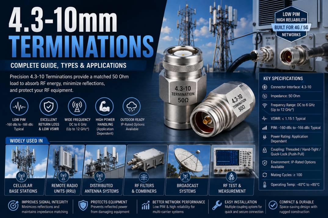
4.3-10mm Terminations, commonly written as 4.3-10 RF Terminations or 4.3/10 Terminations, are precision RF loads designed to terminate coaxial transmission lines and absorb unwanted radio frequency energy. They are primarily used in 50 Ohm RF systems where signal reflection, passive intermodulation, and impedance mismatch can affect network performance.
The 4.3-10 interface was developed for modern mobile communication infrastructure as a compact, high-performance alternative to larger RF connector systems such as 7/16 DIN. It is particularly suited to cellular base stations, distributed antenna systems, remote radio units, antennas, broadcast systems, RF filters, combiners, and other wireless infrastructure.
A 4.3-10 Termination provides a matched RF load at an unused port. Instead of allowing the RF signal to reflect back into the system, the termination absorbs the incident energy. This helps maintain impedance matching, reduce VSWR, improve return loss, and protect RF equipment from unwanted reflected power.
What Is a 4.3-10 Termination?
A 4.3-10 Termination is a 50 Ohm RF termination fitted with a 4.3-10 coaxial interface. It is also commonly called an RF load, dummy load, or termination load.
The main purpose of the component is to provide a controlled impedance at the end of an RF transmission path. When the termination impedance matches the characteristic impedance of the cable or equipment, signal reflections are minimized.
The 4.3-10 connector itself is a 50 Ohm RF interface standardized under IEC 61169-54. Its name comes from its approximate conductor dimensions, including a 4.35 mm inner conductor diameter and a 10 mm outer-conductor dimension.
How Does a 4.3-10 Termination Work?
RF signals travel through a coaxial transmission line toward the connected load. If the load has the same impedance as the transmission line, most of the signal energy is absorbed by the load.
If an RF port is left open or connected to an incorrect impedance, a portion of the signal can be reflected toward the source.
These reflections can result in:
- Higher VSWR
- Lower return loss
- Signal distortion
- Reduced network efficiency
- Measurement errors
- Increased interference
- Unwanted RF stress on equipment
A 4.3-10 Termination provides a matched 50 Ohm load that absorbs the incoming RF energy and minimizes these unwanted effects.
Why Are 4.3-10 Terminations Important?
Modern cellular and wireless communication systems frequently operate with multiple carriers, high transmit power, and complex antenna configurations. In these environments, passive intermodulation and impedance mismatch can significantly affect network performance.
4.3-10 Terminations are designed for these demanding RF environments and can provide low-PIM performance, compact installation, and reliable electrical characteristics. Manufacturers commonly specify low-PIM performance in the region of -160 dBc to -166 dBc depending on the product and test conditions.
They are especially useful for:
- Terminating unused RF ports
- RF test systems
- Cellular base stations
- Distributed antenna systems
- Remote radio units
- RF filters
- RF combiners
- Antenna systems
- Broadcast infrastructure
- Wireless communication equipment
50 Ohm Impedance of 4.3-10 Terminations
4.3-10 RF interfaces are designed around a nominal 50 Ohm impedance.
The 50 Ohm standard is widely used throughout RF and microwave systems because it provides a practical balance between power-handling capability and transmission-line loss.
A properly matched 50 Ohm termination helps minimize signal reflection and provides a predictable RF load.
Maintaining impedance becomes particularly important in multi-carrier cellular networks, where even relatively small RF imperfections can contribute to degraded signal quality.
Frequency Range of 4.3-10 Terminations
Many commercially available 4.3-10 Terminations are designed for operation from DC to 6 GHz. Some specialized 4.3-10 connector systems are specified for operation up to 12 GHz. Therefore, the actual frequency range depends on the specific termination design and manufacturer.
For a termination intended for a particular application, engineers should verify:
- Minimum operating frequency
- Maximum operating frequency
- VSWR across frequency
- Return loss
- Power rating
- PIM performance
For standard cellular infrastructure applications, DC to 6 GHz is a common specification.
Key Features of 4.3-10 Terminations
50 Ohm RF Interface
The 4.3-10 interface provides a standardized 50 Ohm RF connection for wireless infrastructure.
Low Passive Intermodulation
Low-PIM construction helps minimize unwanted intermodulation products in multi-carrier systems.
Compact Construction
The 4.3-10 interface is significantly more compact than traditional 7/16 DIN interfaces, making it suitable for high-density RF installations.
Excellent RF Performance
Precision construction supports stable impedance, low VSWR, and reliable signal transmission.
Multiple Coupling Options
4.3-10 systems are available with different coupling mechanisms, including threaded, hand-tight, and quick-lock or push-pull configurations.
Outdoor Compatibility
Depending on the specific product design, 4.3-10 components can be supplied with IP-rated environmental protection for outdoor telecommunications installations.
High Power Capability
4.3-10 systems are designed for demanding wireless infrastructure applications, with power ratings depending on the specific product and frequency. Some connector products are rated around 500 W at 2 GHz.
Construction of 4.3-10 Terminations
A high-quality 4.3-10 Termination is manufactured using precision RF components and materials.
4.3-10 Connector Body
The connector body provides mechanical support and maintains the required RF geometry.
Center Contact
The center contact provides the electrical connection between the RF port and the internal termination element.
Precision Resistor
The internal resistive element creates the matched 50 Ohm load and converts incoming RF energy into heat.
Outer Conductor
The outer conductor provides the RF return path and contributes to electromagnetic shielding.
Insulator
A suitable dielectric material maintains controlled spacing between the center and outer conductors.
Plated Surfaces
RF-compatible plating improves conductivity, corrosion resistance, and long-term connector reliability.
Technical Specifications of 4.3-10 Terminations
Typical specifications for 4.3-10 RF Terminations can include:
Connector Interface: 4.3-10
Impedance: 50 Ohm
Typical Frequency Range: DC to 6 GHz
Specialized Frequency Range: Up to 12 GHz depending on design
Connector Gender: Male or Female
VSWR: Application dependent
Return Loss: Application dependent
PIM: Low-PIM versions available
Power Rating: Product dependent
Coupling: Threaded, hand-tight, or quick-lock/push-pull depending on design
Environmental Protection: IP-rated versions available
Mating Cycles: Typically 100 or more for many commercial designs
Operating Temperature: Product dependent
These specifications can vary considerably between standard RF loads, high-power terminations, low-PIM terminations, and outdoor-rated products.
Types of 4.3-10 Terminations
4.3-10 Male Termination
A male 4.3-10 Termination is designed to connect to a compatible female 4.3-10 RF interface.
It can be used on:
- RF equipment
- Test fixtures
- Antenna systems
- Filters
- Combiners
- Cellular infrastructure
4.3-10 Female Termination
A female 4.3-10 Termination connects to a compatible male RF interface and is available for equipment, panel, and cable applications.
Low-PIM 4.3-10 Termination
Low-PIM terminations are designed specifically for cellular and multi-carrier RF systems where passive intermodulation performance is critical.
High-Power 4.3-10 Termination
High-power versions are designed to absorb greater RF power while maintaining acceptable temperature and electrical performance.
Outdoor 4.3-10 Termination
Outdoor versions may incorporate environmental sealing and corrosion-resistant construction for telecom tower and antenna installations.
What Is PIM in a 4.3-10 Termination?
PIM stands for Passive Intermodulation.
PIM occurs when passive RF components generate unwanted frequencies when exposed to multiple RF signals. These unwanted products can interfere with desired communication signals.
PIM is especially important in cellular infrastructure because modern networks use multiple frequency bands and carriers.
Low-PIM 4.3-10 Terminations are therefore designed using carefully controlled materials, contact surfaces, mechanical interfaces, and manufacturing processes.
The separation of electrical and mechanical paths in the 4.3-10 connector architecture is one reason the interface is well suited to low-PIM applications.
VSWR and Return Loss in 4.3-10 Terminations
VSWR and return loss are two important parameters used to evaluate termination performance.
A low VSWR indicates that the termination closely matches the 50 Ohm transmission system.
Higher return loss generally indicates better impedance matching because less signal power is reflected toward the source.
For example, a commercial 4.3-10 RF load may be specified at a maximum VSWR of 1.15:1 across DC to 6 GHz, while other designs may have different limits.
The actual specification should always be evaluated over the complete frequency range rather than at a single operating point.
Power Handling of 4.3-10 Terminations
Power handling is one of the most important considerations when selecting an RF termination.
The maximum power depends on:
- Operating frequency
- Internal resistor technology
- Heat dissipation
- Housing design
- Ambient temperature
- Duration of operation
- RF waveform
- Termination construction
For example, commercially available 4.3-10 loads may be rated at 2 W, 10 W, or significantly higher depending on their intended application. Therefore, power ratings should never be assumed solely from the connector type.
High-power applications require a termination specifically designed and rated for the required RF power.
Applications of 4.3-10 Terminations
Cellular Base Stations
4.3-10 Terminations are widely used in cellular infrastructure because the interface was specifically designed around modern mobile communication requirements.
4G LTE Networks
The compact and low-PIM design makes 4.3-10 components suitable for LTE infrastructure and multi-carrier RF systems.
5G Networks
5G networks require reliable RF connections with excellent PIM and signal integrity. 4.3-10 components are commonly used in wireless infrastructure, including base stations and antenna systems.
Distributed Antenna Systems
DAS installations use multiple RF paths and components. Terminations help properly terminate unused or test ports.
Remote Radio Units
4.3-10 interfaces are commonly used for RF connections between radio equipment and antenna systems.
RF Filters and Combiners
Unused ports on RF filters, combiners, and related passive components can be terminated using suitable 4.3-10 loads.
Broadcast Systems
Low-PIM and reliable RF performance make 4.3-10 components useful in professional broadcast infrastructure.
RF Test and Measurement
4.3-10 Terminations can be used with RF test equipment, test benches, cable assemblies, and calibration systems.
Wireless Infrastructure
They are suitable for antenna feeders, RF distribution networks, and other wireless communication installations.
Benefits of 4.3-10 Terminations
Reduced Signal Reflections
A matched 50 Ohm load absorbs RF energy and minimizes unwanted reflections.
Improved Signal Integrity
Reduced reflections and low PIM help maintain clean RF transmission.
Compact Installation
The compact 4.3-10 interface enables higher-density RF equipment layouts compared with larger legacy interfaces.
Low PIM Performance
Low-PIM designs are suitable for demanding multi-carrier cellular networks.
Reliable Outdoor Operation
IP-rated variants can provide protection against dust and moisture in suitable outdoor installations.
Easy Installation
The availability of different coupling mechanisms makes installation and maintenance easier in telecom environments.
High Mechanical Reliability
Many 4.3-10 connector systems are designed for at least 100 mating cycles, although exact ratings depend on the product.
4.3-10 vs 7/16 DIN Terminations
4.3-10 was developed as a more compact alternative for modern mobile communication infrastructure.
Compared with 7/16 DIN, 4.3-10 systems can offer:
- Smaller size
- Lower weight
- Lower coupling torque
- Low-PIM performance
- Multiple coupling mechanisms
- Better suitability for high-density installations
Rosenberger states that its 4.3-10 system is approximately 40% smaller than 7/16 connectors and offers substantially reduced weight.
The choice between the two depends on power requirements, mechanical compatibility, existing infrastructure, frequency, and application conditions.
4.3-10 vs 2.2-5 Terminations
Both interfaces are used in modern wireless infrastructure, but they are designed for different mechanical and performance requirements.
4.3-10 is a larger interface than 2.2-5 and is commonly selected where higher power capability and robust outdoor telecom performance are required.
The appropriate connector should be selected according to:
- RF power
- Frequency
- PIM requirement
- Mechanical space
- Cable type
- Environmental requirements
How to Choose the Right 4.3-10 Termination
Check the Impedance
Confirm that the termination is designed for the required 50 Ohm RF system.
Check the Frequency Range
Make sure the termination supports the maximum operating frequency of the application.
Verify Power Rating
Select a termination that can safely dissipate the required RF power.
Check PIM Performance
For cellular and multi-carrier applications, choose a low-PIM termination with an appropriate PIM specification.
Select the Correct Connector Gender
Check whether the equipment requires a male or female 4.3-10 interface.
Consider Environmental Protection
For outdoor installations, select an appropriately sealed and IP-rated product.
Check VSWR and Return Loss
Precision RF applications should use terminations with suitable VSWR and return-loss specifications.
Consider Coupling Type
Choose threaded, hand-tight, or quick-lock/push-pull configurations according to installation requirements.
Common Mistakes When Using 4.3-10 Terminations
Common installation and selection mistakes include:
- Using the wrong connector gender
- Selecting an incorrect impedance
- Exceeding the rated RF power
- Ignoring frequency limitations
- Using a standard termination where low PIM is required
- Mixing incompatible connector interfaces
- Applying excessive mechanical torque
- Leaving outdoor connections improperly sealed
- Using damaged mating surfaces
- Ignoring VSWR specifications
Installation and Handling Guidelines
Proper handling is important for maintaining RF performance.
Before installation, inspect the connector mating surfaces for dust, contamination, damage, or corrosion.
Ensure that the mating interfaces are correctly aligned before coupling.
Do not force the connector into position.
Use the recommended coupling method and torque specified by the manufacturer.
For outdoor applications, ensure that the complete RF connection has the required environmental protection.
Avoid unnecessary repeated mating and unmating because mechanical wear can eventually affect RF performance.
Maintenance of 4.3-10 Terminations
Regular inspection can help maintain long-term reliability.
Recommended practices include:
- Keep RF interfaces clean
- Use protective caps when disconnected
- Inspect connector surfaces
- Check for corrosion
- Avoid excessive torque
- Inspect environmental seals
- Verify RF performance when required
- Replace damaged terminations
- Store unused components in clean and dry conditions
4.3-10 Terminations for 4G and 5G Infrastructure
The 4.3-10 interface is strongly associated with modern mobile communication infrastructure because it was developed to address the requirements of high-density cellular networks.
4G and 5G networks increasingly use multiple antennas, multiple carriers, MIMO configurations, remote radio units, and distributed antenna systems.
In these environments, low PIM, compact size, reliable mechanical coupling, and stable RF performance are important.
4.3-10 Terminations provide a practical solution for unused RF ports, test connections, and controlled loads within these systems.
4.3-10 Terminations for DAS Applications
Distributed Antenna Systems use multiple antennas and RF distribution components to provide wireless coverage throughout buildings, transportation facilities, stadiums, campuses, and other locations.
DAS systems can contain:
- Splitters
- Couplers
- Filters
- Combiners
- Feeders
- Antennas
- Remote units
Unused ports within these systems should be properly terminated to maintain impedance matching.
Low-PIM 4.3-10 Terminations are especially useful where multiple RF carriers are present.
4.3-10 Terminations for RF Testing
RF laboratories and field engineers use terminations to create controlled RF loads during testing.
Applications include:
- Cable testing
- RF equipment testing
- Antenna testing
- Filter testing
- Combiner testing
- Amplifier testing
- Signal generator testing
- Network troubleshooting
- RF calibration
A high-quality termination can provide a predictable load and help improve measurement repeatability.
Quality Factors to Consider
When sourcing 4.3-10 Terminations, important quality factors include:
- Precision impedance
- Low VSWR
- High return loss
- Low PIM
- Stable power handling
- High-quality materials
- Precision machining
- Reliable plating
- Environmental sealing
- Mechanical durability
- Consistent RF performance
For critical telecom applications, manufacturers should provide complete electrical and mechanical specifications.
Why Choose High-Quality 4.3-10 Terminations?
A high-quality 4.3-10 Termination provides a reliable combination of electrical and mechanical performance.
Important advantages include:
- Accurate 50 Ohm impedance
- Low signal reflection
- Low VSWR
- High return loss
- Low PIM
- Compact construction
- Reliable RF performance
- Durable mechanical design
- Outdoor-ready options
- Compatibility with modern telecom infrastructure
For cellular, DAS, 4G, 5G, broadcast, and RF test applications, selecting the correct termination can help improve system reliability and signal integrity.
Conclusion
4.3-10mm Terminations are precision 50 Ohm RF loads designed for modern wireless communication and RF infrastructure. They absorb unwanted RF energy, reduce signal reflections, maintain impedance matching, and provide controlled termination of unused RF ports.
The 4.3-10 interface is particularly valuable in cellular base stations, 4G LTE and 5G networks, DAS installations, remote radio units, antennas, filters, combiners, broadcast systems, and RF testing environments.
Low-PIM performance is one of the most important advantages of 4.3-10 technology for modern multi-carrier networks. Compact dimensions, multiple coupling mechanisms, reliable RF characteristics, and the availability of environmentally protected versions make the interface well suited to demanding telecom installations.
When choosing a 4.3-10 Termination, always evaluate impedance, frequency range, power rating, VSWR, return loss, PIM performance, connector gender, coupling mechanism, and environmental requirements.
Frequently Asked Questions About 4.3-10 Terminations
What is a 4.3-10 Termination?
A 4.3-10 Termination is a 50 Ohm RF load equipped with a 4.3-10 connector interface. It absorbs RF energy and minimizes unwanted signal reflections.
What is the impedance of a 4.3-10 Termination?
4.3-10 RF interfaces are designed for a nominal 50 Ohm impedance.
What frequency range do 4.3-10 Terminations support?
Many 4.3-10 Terminations support DC to 6 GHz, while specialized 4.3-10 systems can support frequencies up to 12 GHz. The exact range depends on the specific product.
Are 4.3-10 Terminations low PIM?
Low-PIM 4.3-10 Terminations are specifically available for cellular and multi-carrier applications. PIM performance varies by product and should be checked against the manufacturer’s specification.
Where are 4.3-10 Terminations used?
They are used in cellular base stations, 4G LTE, 5G networks, DAS, remote radio units, antennas, filters, combiners, broadcast systems, wireless infrastructure, and RF test equipment.
Why is low PIM important in 4.3-10 Terminations?
Low PIM reduces unwanted intermodulation products that can interfere with cellular communication signals, making it important for multi-carrier RF networks.
Are 4.3-10 Terminations available in male and female versions?
Yes. 4.3-10 Terminations are available in male and female configurations depending on the equipment and application.
Can 4.3-10 Terminations be used outdoors?
Yes. Outdoor-rated versions are available with environmental sealing and IP-rated protection, depending on the manufacturer and product design.
How much power can a 4.3-10 Termination handle?
Power handling varies significantly between products. Some low-power RF loads may handle only a few watts, while specialized high-power designs can handle substantially more. Always check the specific manufacturer’s rating.
What is the difference between a 4.3-10 and 7/16 DIN termination?
4.3-10 is a more compact RF interface designed for modern wireless infrastructure. It offers low-PIM performance and multiple coupling options while occupying less space than traditional 7/16 DIN systems.
Are 4.3-10 Terminations suitable for 5G?
Yes. 4.3-10 components are widely used in modern cellular infrastructure and are particularly suitable for low-PIM, high-density RF applications associated with 4G and 5G networks.
How do I select the right 4.3-10 Termination?
Check the required impedance, frequency range, power rating, VSWR, return loss, PIM specification, connector gender, environmental rating, and coupling mechanism before selecting a product.