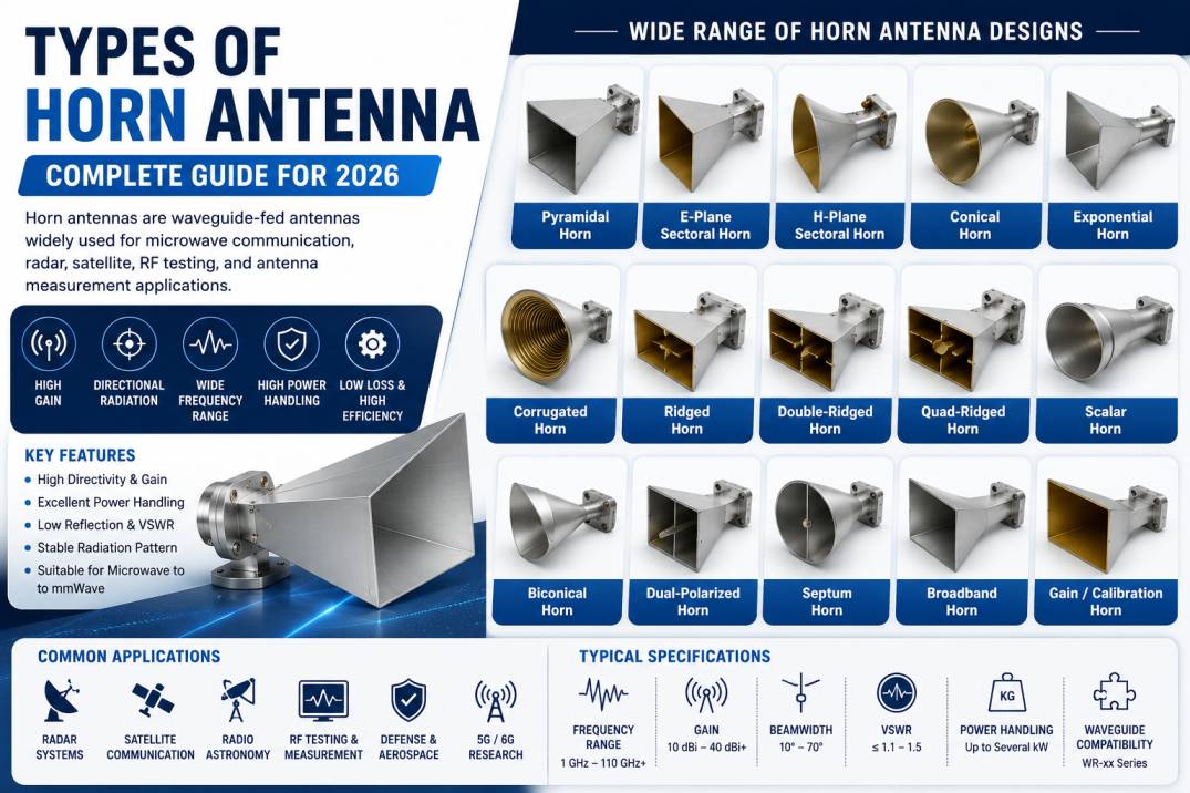
Horn antennas are widely used microwave and RF antennas designed to provide directional radiation, high efficiency, and reliable performance across a broad range of frequencies. They are commonly used in radar systems, satellite communication, aerospace and defense, radio astronomy, electromagnetic testing, antenna measurement systems, and microwave links.
A horn antenna is essentially a flared waveguide that gradually transforms electromagnetic energy traveling inside a waveguide into a radiated electromagnetic wave. Its simple mechanical structure, low loss, high power-handling capability, and predictable radiation characteristics make it one of the most important antenna types in microwave engineering.
Different horn antenna geometries provide different beamwidths, polarization characteristics, gain levels, frequency ranges, and radiation patterns. The most common designs include pyramidal horn antennas, conical horn antennas, sectoral horns, corrugated horns, ridged horns, dual-polarized horns, and specialized broadband horn antennas.
This comprehensive guide explains the different types of horn antennas, their construction, working principles, characteristics, advantages, applications, specifications, and selection criteria.
What Is a Horn Antenna?
A horn antenna is a directional antenna formed by gradually flaring the open end of a waveguide.
The waveguide carries electromagnetic energy toward the antenna aperture. As the waveguide expands, the electromagnetic field transitions into free-space radiation.
The basic structure consists of:
- Waveguide feed
- Flared section
- Antenna aperture
- Mechanical body
- Mounting arrangement
- Optional polarization or mode-control structures
Horn antennas can be designed for rectangular or circular waveguide systems depending on the desired electromagnetic mode and application.
How Does a Horn Antenna Work?
A horn antenna operates by expanding the cross-sectional area of a waveguide toward an open aperture.
Inside the waveguide, electromagnetic energy is confined and travels toward the horn opening. The gradually increasing dimensions reduce the abrupt transition between the guided wave and free-space radiation.
The flare provides several important benefits:
- Improved impedance transition
- Directional radiation
- Increased aperture size
- Controlled beamwidth
- High efficiency
- Reduced reflection
- Improved gain
The amount and shape of the flare determine the antenna’s radiation characteristics.
Why Are Horn Antennas Important in RF and Microwave Systems?
Horn antennas offer several characteristics that make them particularly useful at microwave and millimeter-wave frequencies.
Key advantages include:
- High gain
- High directivity
- Low insertion loss
- Wide frequency capability
- Excellent power handling
- Stable radiation characteristics
- Simple mechanical construction
- Reliable operation at high frequencies
- Good polarization purity in suitable designs
- Easy integration with waveguide systems
Horn antennas are also frequently used as reference antennas because their radiation characteristics can be accurately modeled and measured.
Main Types of Horn Antennas
The major types of horn antennas include:
- Pyramidal Horn Antenna
- E-Plane Sectoral Horn Antenna
- H-Plane Sectoral Horn Antenna
- Conical Horn Antenna
- Exponential Horn Antenna
- Corrugated Horn Antenna
- Ridged Horn Antenna
- Double-Ridged Horn Antenna
- Quad-Ridged Horn Antenna
- Scalar Horn Antenna
- Biconical Horn Antenna
- Dual-Polarized Horn Antenna
- Septum Horn Antenna
- Broadband Horn Antenna
- Gain Horn Antenna
- Standard Calibration Horn Antenna
1. Pyramidal Horn Antenna
A pyramidal horn antenna is one of the most commonly used rectangular-waveguide horn designs.
It is formed by flaring a rectangular waveguide in both the E-plane and H-plane.
The resulting aperture has a rectangular or approximately rectangular shape.
Features
- Rectangular aperture
- Directional radiation
- High gain
- Good impedance characteristics
- Suitable for microwave frequencies
- Compatible with rectangular waveguides
Applications
Pyramidal horn antennas are commonly used in:
- Radar
- Microwave communication
- Antenna measurements
- RF testing
- Electromagnetic compatibility testing
- Satellite systems
- Laboratory measurements
Advantages
The pyramidal horn provides a practical balance between gain, beamwidth, mechanical simplicity, and bandwidth.
2. E-Plane Sectoral Horn Antenna
An E-plane sectoral horn is created by flaring a rectangular waveguide primarily in the E-plane while maintaining the H-plane dimension relatively constant.
This geometry modifies the radiation pattern primarily in the electric-field plane.
Characteristics
- E-plane flare
- Controlled E-plane beamwidth
- Rectangular waveguide feed
- Directional radiation
- Simple construction
Applications
- Microwave measurements
- Antenna testing
- Educational laboratories
- Radar systems
- RF characterization
3. H-Plane Sectoral Horn Antenna
An H-plane sectoral horn is flared primarily in the H-plane.
The design produces a different radiation pattern compared with an E-plane sectoral horn.
Applications
- Microwave laboratory systems
- Antenna measurements
- Waveguide testing
- Radar research
- RF instrumentation
Advantages
The H-plane flare provides engineers with additional control over beamwidth and aperture dimensions.
4. Conical Horn Antenna
It is one of the most widely used horn structures for applications requiring circular symmetry.
A conical horn antenna uses a circular waveguide that gradually expands into a circular or conical aperture.
Features
- Circular aperture
- Conical flare
- Circular waveguide feed
- Symmetrical radiation characteristics
- Directional beam
- Suitable for circular polarization systems when appropriately configured
Applications
- Satellite communication
- Radar
- Radio astronomy
- Microwave links
- Antenna testing
- Space communication
Advantages
Conical horns can provide symmetrical beam characteristics and are useful when the antenna system requires a circular aperture.
5. Exponential Horn Antenna
An exponential horn has a flare profile that follows an exponential relationship rather than a simple linear expansion.
The gradual change in waveguide dimensions can provide useful impedance and broadband characteristics.
Features
- Smooth flare profile
- Broadband potential
- Controlled impedance transition
- Low reflection characteristics
- Microwave applications
Applications
- Broadband microwave systems
- RF measurements
- Antenna testing
- Electromagnetic research
- Specialized communication systems
6. Corrugated Horn Antenna
A corrugated horn antenna contains grooves or corrugations along the inside wall of the horn.
These corrugations modify the electromagnetic boundary conditions and can significantly improve polarization performance and radiation characteristics.
Features
- Low sidelobes
- Excellent polarization purity
- Low cross-polarization
- Symmetrical radiation pattern
- High efficiency
- Suitable for precision microwave applications
Applications
Corrugated horn antennas are commonly used in:
- Satellite communication
- Radio astronomy
- Deep-space communication
- Earth observation
- Precision radar
- Antenna measurement systems
Why Are Corrugated Horns Important?
Corrugated horns are particularly valuable when low sidelobe levels and high polarization purity are critical.
They are widely used in high-performance reflector antenna feeds.
7. Ridged Horn Antenna
A ridged horn antenna incorporates one or more conductive ridges inside the waveguide and horn structure.
The ridges modify the electromagnetic field distribution and can significantly increase the operational bandwidth.
Features
- Wide bandwidth
- Compact aperture
- Broadband impedance characteristics
- Directional radiation
- Suitable for wide-frequency measurements
Applications
- EMC testing
- EMI testing
- Antenna measurements
- RF laboratories
- Broadband communication
- Electronic warfare testing
8. Double-Ridged Horn Antenna
A double-ridged horn contains two internal ridges positioned along the waveguide structure.
This configuration is commonly used to achieve broad frequency coverage.
Advantages
- Very wide bandwidth
- Good impedance matching
- Compact design
- Suitable for broadband measurements
- High-frequency capability
Applications
- EMC testing
- RF immunity testing
- Antenna measurements
- Spectrum monitoring
- Electronic warfare
- Broadband RF testing
Double-ridged horn antennas are particularly useful when one antenna needs to cover multiple microwave frequency ranges.
9. Quad-Ridged Horn Antenna
A quad-ridged horn uses four ridges to create a broadband antenna structure that can support dual-polarized operation.
The design can provide very wide frequency coverage while maintaining useful polarization characteristics.
Applications
- Wideband radar
- Electronic warfare
- Signal intelligence
- Direction finding
- EMC testing
- Broadband communication
- Antenna measurement systems
Advantages
- Extremely broad frequency coverage
- Dual-polarization capability
- High-frequency performance
- Suitable for wideband applications
10. Scalar Horn Antenna
A scalar horn antenna is generally associated with circular waveguide structures and can include a profiled aperture designed to control electromagnetic fields.
Scalar horns are often used as feeds for reflector antennas.
Applications
- Satellite communication
- Earth stations
- Radio astronomy
- Reflector antenna systems
- Microwave links
Benefits
- Controlled radiation pattern
- Good reflector illumination
- Low sidelobe potential
- Useful feed characteristics
11. Biconical Horn Antenna
A biconical horn combines features of conical and biconical structures to provide broadband electromagnetic performance.
Biconical antenna concepts are particularly useful when wide frequency coverage is required.
Applications
- EMC measurements
- Broadband RF testing
- Electromagnetic field measurements
- Antenna research
- Spectrum monitoring
Biconical configurations can be used where broadband operation is more important than extremely high gain.
12. Dual-Polarized Horn Antenna
A dual-polarized horn antenna supports two orthogonal polarization components.
This allows the antenna to transmit or receive two polarization states and can be useful for MIMO, radar, satellite, and measurement applications.
Common Polarizations
- Vertical
- Horizontal
- Orthogonal linear polarization
- Circular polarization through suitable feed structures
Applications
- Radar
- Satellite communication
- Polarimetric measurements
- Radio astronomy
- MIMO systems
- Remote sensing
13. Septum Horn Antenna
A septum horn antenna uses a septum or internal partition structure to control polarization or mode conversion.
It is commonly associated with circular polarization and specialized microwave applications.
Applications
- Radar
- Satellite communication
- Aerospace systems
- Navigation
- Remote sensing
- Polarization-sensitive communication
The internal septum structure allows the antenna to generate or receive particular polarization states.
14. Broadband Horn Antenna
Broadband horn antennas are designed to operate across a wide frequency range.
Ridged and quad-ridged designs are examples of structures commonly used to achieve broadband operation.
Benefits
- Wide frequency coverage
- Reduced need for multiple antennas
- Useful for frequency scanning
- Suitable for test and measurement
- Flexible RF system integration
Applications
- Spectrum monitoring
- EMC testing
- Electronic warfare
- Radar
- Signal intelligence
- Broadband communication
15. Gain Horn Antenna
A gain horn antenna is a precision horn antenna designed to provide a known and stable gain value.
Gain horns are commonly used as reference antennas for RF measurements and calibration.
Applications
- Antenna calibration
- Gain measurements
- RF laboratory testing
- Free-space measurements
- VNA measurements
- Microwave system characterization
The controlled design of a gain horn allows engineers to use it as a reference when evaluating other antennas.
16. Standard Calibration Horn Antenna
Calibration horn antennas are manufactured with carefully controlled mechanical and electrical characteristics.
They are used as reference standards in antenna measurement systems.
Applications
- Antenna test ranges
- RF laboratories
- Microwave calibration
- Gain measurements
- Radiation pattern measurements
- Electromagnetic testing
High-quality calibration horns typically require precise manufacturing and characterization.
Horn Antenna Classification by Geometry
Horn antennas can also be classified according to their physical shape.
| Horn Type | Feed Type | Main Characteristic |
|---|---|---|
| Pyramidal | Rectangular waveguide | Flared in E and H planes |
| E-Plane Sectoral | Rectangular waveguide | E-plane flare |
| H-Plane Sectoral | Rectangular waveguide | H-plane flare |
| Conical | Circular waveguide | Circular aperture |
| Corrugated | Circular/modified waveguide | Low sidelobes and low cross-polarization |
| Ridged | Rectangular/ridged waveguide | Wide bandwidth |
| Double-Ridged | Ridged waveguide | Very wide bandwidth |
| Quad-Ridged | Four-ridge structure | Broadband dual polarization |
| Scalar | Circular waveguide | Reflector feed applications |
| Septum | Circular or specialized feed | Polarization control |
Horn Antenna Frequency Range
Horn antennas can operate from microwave frequencies into the millimeter-wave range, depending on their physical dimensions and waveguide design.
The operating frequency is closely related to the waveguide dimensions.
As frequency increases:
- Waveguide dimensions generally become smaller
- Aperture dimensions become smaller
- Manufacturing tolerances become more critical
- Connector and flange tolerances become more important
- Surface finish can become more significant
Horn antennas can be designed for frequency ranges from a few gigahertz to extremely high microwave and millimeter-wave frequencies.
Horn Antenna Gain
Horn antenna gain depends on several factors, including:
- Aperture size
- Operating wavelength
- Flare angle
- Aperture efficiency
- Waveguide mode
- Antenna geometry
A simplified relationship between aperture size and gain can be expressed conceptually as:
Gain ∝ Aperture Area / Wavelength²
This means that for a given physical aperture, gain generally increases as frequency increases.
However, actual gain depends on aperture efficiency and the complete electromagnetic design.
Horn Antenna Beamwidth
Beamwidth describes the angular width of the main radiation lobe.
Commonly evaluated beamwidth parameters include:
- E-plane beamwidth
- H-plane beamwidth
- Half-power beamwidth
- First-null beamwidth
A larger aperture generally produces a narrower beam, while a smaller aperture produces a wider beam.
Beamwidth is an important specification in radar, satellite, testing, and microwave communication applications.
Horn Antenna Radiation Pattern
The radiation pattern describes how RF energy is distributed around the antenna.
Important characteristics include:
- Main beam
- Sidelobes
- Back radiation
- Beamwidth
- Cross-polarization
- Front-to-back ratio
High-performance horn antennas are often designed to provide a strong main beam with controlled sidelobe levels.
Horn Antenna Polarization
Polarization defines the orientation of the electromagnetic field.
Horn antennas can support:
- Linear polarization
- Dual linear polarization
- Circular polarization
- Orthogonal polarization
The polarization depends on the feed, waveguide mode, aperture geometry, and any internal structures such as septums or corrugations.
Horn Antenna Impedance
Most horn antennas are designed to work with a standard RF impedance, commonly 50 ohms, depending on the complete measurement or communication system.
Proper impedance matching minimizes reflections between the antenna and connected RF equipment.
Important related parameters include:
- VSWR
- Return loss
- Reflection coefficient
- Input impedance
Horn Antenna VSWR
VSWR is used to evaluate how effectively the antenna is matched to the transmission system.
A low VSWR generally indicates that less RF power is reflected toward the source.
For precision RF systems, VSWR should be evaluated over the entire specified frequency range.
Horn Antenna Efficiency
Antenna efficiency represents the proportion of input RF power that is effectively converted into radiated electromagnetic energy.
Horn antennas are generally known for high efficiency because they do not require complex lossy dielectric structures in the main radiating aperture.
Efficiency can still be influenced by:
- Conductor losses
- Surface finish
- Waveguide losses
- Aperture design
- Manufacturing accuracy
- Frequency
Horn Antenna Directivity
Horn antennas are highly directional because their aperture concentrates electromagnetic radiation into a relatively narrow beam.
Directivity is especially useful in applications where RF energy needs to be transmitted or received from a specific direction.
Examples include:
- Radar
- Point-to-point communication
- Satellite links
- Antenna testing
- Radio astronomy
Horn Antenna Applications
Horn antennas are used across a wide range of RF and microwave applications.
Radar Systems
Radar systems use horn antennas as feeds, reference antennas, measurement antennas, and in some specialized radar architectures.
Satellite Communication
Horn antennas are frequently used as feed antennas for satellite reflector systems.
They can provide controlled radiation patterns and good polarization characteristics.
Aerospace and Defense
Horn antennas are used in:
- Radar
- Electronic warfare
- Electronic intelligence
- Direction finding
- RF testing
- Missile systems
- Aircraft communication
- Threat simulation
Antenna Measurement
Horn antennas are widely used as reference antennas in antenna measurement facilities.
They can be used to evaluate:
- Gain
- Radiation pattern
- Beamwidth
- Polarization
- Sidelobes
- Antenna efficiency
EMC and EMI Testing
Broadband horn antennas are commonly used for electromagnetic compatibility measurements, especially at microwave frequencies.
Radio Astronomy
Low-sidelobe and low-cross-polarization horn antennas are used in radio astronomy and precision microwave measurements.
5G and 6G Research
Horn antennas are useful in high-frequency wireless research because they provide predictable directional characteristics.
They are commonly used for:
- Channel measurements
- Beam characterization
- Propagation experiments
- mmWave testing
- Antenna measurements
Horn Antennas in Microwave Test and Measurement
Horn antennas are extremely valuable in RF laboratories.
They can be connected to:
- Vector Network Analyzers
- Signal generators
- Spectrum analyzers
- Power meters
- Antenna measurement systems
- Frequency converters
Two horn antennas can also be used in free-space transmission measurements to evaluate RF devices and materials.
Horn Antennas for VNA Measurements
A Vector Network Analyzer can be used with horn antennas for free-space measurements.
A typical setup may include:
- VNA
- Transmitting horn
- Receiving horn
- Test device or material
- Positioning system
- RF cables
- Calibration standards
This configuration can be used to measure transmission and reflection characteristics.
Horn Antennas for Material Testing
Horn antennas can be used in free-space material characterization.
Applications include:
- Dielectric measurements
- Absorber testing
- Radome testing
- Composite material evaluation
- Microwave material research
The horn antenna provides a controlled electromagnetic beam directed toward the material under test.
Horn Antenna vs Dish Antenna
Horn and parabolic dish antennas are both directional antennas, but they operate differently.
| Feature | Horn Antenna | Parabolic Dish |
|---|---|---|
| Structure | Flared waveguide | Reflector dish |
| Feed | Integrated waveguide | Separate feed |
| Gain | Moderate to high | High to very high |
| Beamwidth | Moderate to narrow | Very narrow |
| Size | Compact at microwave frequencies | Can be large |
| Bandwidth | Depends on design | Depends on feed |
| Applications | Testing, radar, microwave | Satellite, backhaul, radar |
Horn antennas are often easier to characterize and can provide a simpler solution for microwave testing.
Horn Antenna vs Patch Antenna
| Feature | Horn Antenna | Patch Antenna |
|---|---|---|
| Radiation | Directional | Broad to moderately directional |
| Gain | Medium to high | Low to moderate |
| Bandwidth | Moderate to wide depending on design | Often narrower |
| Structure | Waveguide-based | Printed |
| Size | Larger at lower frequencies | Compact |
| Power Handling | High | Generally lower |
| Common Use | Microwave testing and radar | Wireless and compact devices |
Advantages of Horn Antennas
Horn antennas offer numerous advantages.
High Directivity
Their flared aperture creates a focused radiation pattern.
High Efficiency
Horn antennas can achieve high efficiency because the main radiating structure is typically metallic and has low dielectric loss.
Wide Frequency Options
Different horn designs can cover narrow or very wide frequency ranges.
High Power Handling
Metallic waveguide structures can handle relatively high RF power compared with many compact printed antennas.
Low Loss
Waveguide-fed horn antennas can provide low transmission losses, particularly at microwave frequencies.
Simple Construction
Despite their sophisticated electromagnetic behavior, many horn antennas have relatively straightforward mechanical construction.
Excellent Measurement Stability
Precision horn antennas can provide repeatable radiation characteristics, making them valuable as measurement references.
Limitations of Horn Antennas
Horn antennas also have certain limitations.
Large Physical Size at Lower Frequencies
Because the antenna dimensions are related to wavelength, horns designed for lower microwave frequencies can become physically large.
Mechanical Requirements
Precision horn antennas require accurate manufacturing to maintain specified RF performance.
Limited Integration in Compact Devices
Horn antennas are generally less suitable for very small consumer wireless products compared with PCB or chip antennas.
Directional Alignment
High-gain horns have narrow beams and require accurate alignment in many applications.
How to Choose the Right Horn Antenna
Choosing the correct horn antenna requires consideration of both electrical and mechanical requirements.
1. Determine the Frequency Range
The first step is to identify the required operating frequency.
For example:
- 2–4 GHz
- 4–8 GHz
- 8–12 GHz
- 12–18 GHz
- 18–26.5 GHz
- 26.5–40 GHz
- 40–50 GHz
- 50–75 GHz
- 75–110 GHz
The antenna must support the complete frequency range required by the application.
2. Select the Horn Geometry
Choose the geometry based on application requirements.
For example:
- Pyramidal for general microwave applications
- Conical for circular waveguide systems
- Corrugated for low sidelobes and high polarization purity
- Ridged for broadband applications
- Quad-ridged for very wideband dual-polarized systems
3. Determine Required Gain
Higher gain usually requires a larger effective aperture or a more focused radiation pattern.
4. Determine Required Beamwidth
Choose beamwidth according to the coverage or measurement requirement.
5. Check Polarization
Verify whether the application requires:
- Linear polarization
- Dual polarization
- Circular polarization
6. Check Waveguide Interface
The waveguide flange and interface must match the connected RF equipment.
Common waveguide interfaces may include different flange families depending on frequency and industry standard.
7. Evaluate VSWR
Check the specified VSWR over the complete operating range.
8. Consider Mechanical Requirements
Important mechanical factors include:
- Mounting holes
- Weight
- Dimensions
- Material
- Surface finish
- Environmental conditions
- Flange configuration
Horn Antenna Specifications
A professional horn antenna datasheet may include:
| Parameter | Description |
|---|---|
| Frequency Range | Operating frequency |
| Gain | Antenna gain in dBi |
| Beamwidth | E-plane and H-plane |
| VSWR | Impedance matching |
| Polarization | Linear, dual, or circular |
| Connector/Flange | RF interface |
| Power Handling | Maximum RF power |
| Sidelobe Level | Off-axis radiation |
| Cross-Polarization | Polarization purity |
| Material | Aluminum, copper, etc. |
| Finish | Conductive surface treatment |
| Dimensions | Mechanical size |
| Weight | Total antenna mass |
Horn Antenna Manufacturing
Precision horn antennas require accurate mechanical manufacturing because even small dimensional errors can influence microwave performance at high frequencies.
Typical manufacturing processes include:
- CNC machining
- Sheet metal fabrication
- Precision milling
- Waveguide machining
- Surface finishing
- Brazing or joining
- Assembly
- RF testing
At millimeter-wave frequencies, manufacturing tolerances become increasingly important because the wavelength becomes very small.
Horn Antenna Testing
Horn antennas can be tested using several RF measurement techniques.
Important tests include:
- VSWR measurement
- Return loss measurement
- Gain measurement
- Radiation pattern measurement
- Beamwidth measurement
- Polarization measurement
- Cross-polarization measurement
- Sidelobe measurement
- Power handling verification
Antenna test chambers are often used when accurate radiation pattern measurements are required.
Future Trends in Horn Antenna Technology
Horn antennas continue to play an important role in high-frequency RF development.
Major trends include:
- Higher-frequency millimeter-wave horns
- Broadband multi-octave designs
- Compact horn antennas
- Quad-ridged broadband antennas
- Dual-polarized designs
- Low-sidelobe antennas
- High-purity polarization designs
- 5G and 6G measurement antennas
- Advanced radar test antennas
- Additive manufacturing of complex RF structures
- Precision antennas for satellite communication
As wireless systems move toward higher frequencies, horn antennas are expected to remain important tools for RF characterization, radar development, satellite communication, and antenna testing.
Conclusion
Horn antennas are fundamental microwave and RF antennas known for high directivity, low loss, excellent power handling, and predictable radiation characteristics.
Different horn geometries are optimized for different applications. Pyramidal horns are widely used with rectangular waveguides, conical horns provide circular symmetry, corrugated horns offer excellent polarization purity and low sidelobes, while ridged and quad-ridged horns provide very wide frequency coverage.
Horn antennas are used extensively in radar, satellite communication, aerospace and defense, radio astronomy, EMC testing, antenna measurements, microwave laboratories, and high-frequency wireless research.
When selecting a horn antenna, engineers should consider frequency range, gain, beamwidth, polarization, VSWR, waveguide interface, power handling, mechanical dimensions, and environmental requirements.
With the continued growth of microwave, millimeter-wave, 5G, 6G, radar, satellite, and advanced RF testing technologies, horn antennas remain an important part of modern high-frequency antenna engineering.
Frequently Asked Questions
1. What is a horn antenna?
A horn antenna is a directional microwave antenna formed by gradually flaring the open end of a waveguide to efficiently radiate electromagnetic energy into free space.
2. What are the main types of horn antennas?
Major types include pyramidal, E-plane sectoral, H-plane sectoral, conical, exponential, corrugated, ridged, double-ridged, quad-ridged, scalar, biconical, dual-polarized, septum, broadband, and gain horn antennas.
3. What is a pyramidal horn antenna?
A pyramidal horn antenna is a rectangular-waveguide antenna flared in both the E-plane and H-plane. It is commonly used for microwave communication, radar, and antenna measurements.
4. What is a conical horn antenna?
A conical horn antenna uses a circular waveguide that expands into a circular aperture. It is commonly used in satellite communication, radar, radio astronomy, and microwave systems.
5. What is a corrugated horn antenna?
A corrugated horn contains grooves inside its walls to control electromagnetic modes. It is known for low sidelobes, low cross-polarization, and excellent polarization purity.
6. What is a ridged horn antenna?
A ridged horn incorporates conductive ridges into its waveguide structure to increase bandwidth and improve broadband impedance characteristics.
7. What is a double-ridged horn antenna used for?
Double-ridged horn antennas are widely used for broadband RF testing, EMC measurements, antenna measurements, spectrum monitoring, and electronic warfare applications.
8. What is a quad-ridged horn antenna?
A quad-ridged horn uses four internal ridges and is designed for extremely wide frequency coverage. Many designs also provide dual-polarized operation.
9. What is horn antenna gain?
Horn antenna gain indicates how effectively the antenna concentrates RF energy in a particular direction compared with an isotropic radiator. It is commonly expressed in dBi.
10. Are horn antennas directional?
Yes. Horn antennas are inherently directional and generally produce a focused main beam.
11. What frequencies can horn antennas operate at?
Horn antennas can be designed for microwave and millimeter-wave frequencies ranging from a few gigahertz to well above 100 GHz, depending on their dimensions and waveguide design.
12. Why are horn antennas used in radar?
Horn antennas provide directional radiation, high efficiency, predictable beam patterns, and good power-handling capability, making them useful in radar systems and radar measurement setups.
13. Can horn antennas be used for satellite communication?
Yes. Horn antennas are frequently used as feed antennas for satellite and reflector antenna systems because of their controlled radiation patterns and polarization characteristics.
14. What is the difference between a horn antenna and a parabolic antenna?
A horn antenna directly radiates energy from a flared waveguide aperture, while a parabolic antenna uses a reflector dish to focus or collimate RF energy from a feed antenna.
15. What is the purpose of a horn antenna in RF testing?
Horn antennas can be used as transmitting or receiving antennas for radiation pattern measurements, gain measurements, free-space material testing, EMC measurements, and microwave characterization.
16. What is a gain horn antenna?
A gain horn is a precision horn antenna designed to provide a known and repeatable gain value. It is often used as a reference antenna during RF measurements.
17. What is the advantage of a broadband horn antenna?
A broadband horn antenna can operate across a wide frequency range, reducing the need for multiple narrowband antennas and making it useful for testing, monitoring, radar, and electronic warfare applications.
18. What is horn antenna polarization?
Horn antenna polarization describes the orientation of the electric field. Horn antennas can be designed for linear, dual-linear, or circular polarization depending on their feed and internal structure.
19. What factors determine horn antenna gain?
Horn antenna gain depends primarily on aperture dimensions, operating wavelength, aperture efficiency, flare geometry, and electromagnetic design.
20. How do I choose the right horn antenna?
Select a horn antenna based on frequency range, gain, beamwidth, polarization, VSWR, waveguide interface, power handling, mechanical dimensions, and application requirements.