A High Gain Yagi Antenna is a directional RF antenna designed to concentrate electromagnetic energy in a specific direction. Known for their relatively high gain, narrow beamwidth, good front-to-back ratio, and simple mechanical construction, Yagi antennas are widely used in wireless communication, cellular networks, RF testing, telemetry, broadcasting, amateur radio, remote monitoring, and long-distance communication systems.
The Yagi antenna is based on a driven element combined with passive elements, typically including reflectors and directors. By carefully controlling the length and spacing of these elements, engineers can create a directional radiation pattern that provides higher forward gain compared with a basic dipole.
High gain Yagi antennas are available for many frequency ranges, including VHF, UHF, cellular, LTE, 5G-related sub-6 GHz applications, Wi-Fi, ISM bands, and specialized RF systems.
Choosing the correct Yagi antenna requires understanding its frequency range, gain, number of elements, beamwidth, polarization, impedance, VSWR, front-to-back ratio, mechanical construction, and installation requirements.
What Is a High Gain Yagi Antenna?
A High Gain Yagi Antenna is a directional antenna consisting of several conductive elements mounted along a supporting boom.
A typical Yagi antenna includes:
- Reflector
- Driven element
- One or more directors
- Supporting boom
- Mounting bracket
- RF feed connection
The driven element is connected to the transmission line, while the reflector and directors are passive elements.
The passive elements interact electromagnetically with the driven element to reinforce radiation in the forward direction and suppress radiation toward the rear.
The result is a directional antenna with increased forward gain.
How Does a Yagi Antenna Work?
A Yagi antenna works through electromagnetic coupling between multiple conductive elements.
The driven element receives the RF signal from the transmitter. The nearby passive elements become electromagnetically excited and re-radiate energy.
The reflector is generally positioned behind the driven element and is slightly longer than the driven element. Directors are positioned in front and are generally shorter.
The dimensions and spacing of these elements determine the antenna’s operating frequency and radiation characteristics.
By properly designing these elements, RF energy is concentrated toward the front of the antenna.
Basic Structure of a High Gain Yagi Antenna
A conventional Yagi antenna contains three primary types of elements.
Reflector
The reflector is located behind the driven element.
Its primary function is to help suppress radiation toward the rear and improve forward directivity.
Driven Element
The driven element is connected to the RF feed line.
It is the active element responsible for coupling the electrical signal into the antenna structure.
Directors
Directors are placed in front of the driven element.
Additional directors can increase directivity and gain, although the relationship is not simply “more elements equals unlimited gain.”
Boom
The boom provides mechanical support and maintains the required spacing between antenna elements.
Mounting Assembly
The mounting assembly attaches the antenna to a mast, pole, tower, wall bracket, or other support structure.
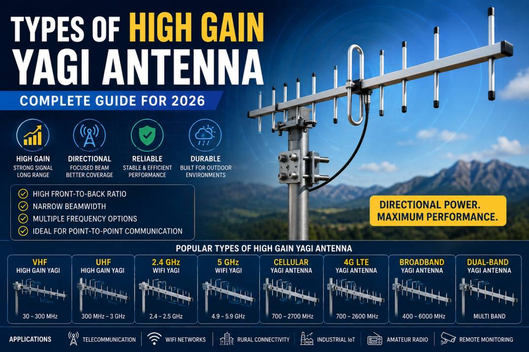
Main Types of High Gain Yagi Antennas
High gain Yagi antennas can be classified according to frequency, number of elements, bandwidth, construction, polarization, and application.
Common types include:
- VHF High Gain Yagi Antenna
- UHF High Gain Yagi Antenna
- 2.4 GHz High Gain Yagi Antenna
- 5 GHz High Gain Yagi Antenna
- Cellular Yagi Antenna
- 3G-4G LTE Yagi Antenna
- 5G Sub-6 GHz Yagi Antenna
- Wi-Fi Yagi Antenna
- ISM Band Yagi Antenna
- Dual-Band Yagi Antenna
- Broadband Yagi Antenna
- Folded Dipole Yagi Antenna
- High Front-to-Back Ratio Yagi Antenna
- Multi-Element Yagi Antenna
- Heavy-Duty Outdoor Yagi Antenna
- Custom Frequency Yagi Antenna
1. VHF High Gain Yagi Antenna
VHF Yagi antennas operate in the Very High Frequency range.
They are generally physically larger than UHF or microwave Yagi antennas because antenna dimensions are related to wavelength.
Applications
VHF Yagi antennas are used for:
- Radio communication
- Amateur radio
- Telemetry
- Remote monitoring
- Broadcasting
- Specialized communication systems
- RF experimentation
Advantages
- High directional gain
- Long propagation characteristics
- Good front-to-back performance
- Suitable for long-distance communication
2. UHF High Gain Yagi Antenna
UHF Yagi antennas are physically smaller than comparable VHF antennas because UHF wavelengths are shorter.
They are commonly used for wireless communication, television reception, telemetry, RFID-related systems, and other UHF applications.
Applications
- UHF communication
- Digital television reception
- Wireless links
- Telemetry
- Remote control systems
- Industrial communication
3. 2.4 GHz High Gain Yagi Antenna
A 2.4 GHz Yagi antenna is designed for applications operating around the 2.4 GHz ISM range.
The 2.4 GHz band is widely used by technologies such as Wi-Fi, Bluetooth, Zigbee, and various industrial wireless systems.
Applications
- Wi-Fi point-to-point links
- Wireless bridges
- Industrial IoT
- Remote monitoring
- ISM communication
- Wireless networking
A 2.4 GHz Yagi can provide a focused beam for applications where an omnidirectional antenna would distribute energy unnecessarily.
4. 5 GHz High Gain Yagi Antenna
5 GHz Yagi antennas are designed for higher-frequency wireless applications.
They are often used for directional Wi-Fi links, wireless bridges, telemetry, and specialized RF communication systems.
Applications
- 5 GHz Wi-Fi
- Wireless backhaul
- Point-to-point communication
- Outdoor wireless networks
- Industrial wireless systems
Because the wavelength is shorter at 5 GHz, the physical dimensions of the antenna elements can be significantly smaller than those of lower-frequency Yagi antennas.
5. Cellular High Gain Yagi Antenna
Cellular Yagi antennas are designed to improve directional reception and transmission for cellular frequency bands.
They can be used in areas where cellular coverage is weak and the direction of the serving base station is known.
Applications
- LTE routers
- Cellular gateways
- Remote monitoring
- Rural broadband
- Industrial IoT
- Cellular telemetry
- Fixed wireless installations
Advantages
- Directional gain
- Improved signal concentration
- Reduced rear radiation
- Suitable for fixed installations
6. 3G-4G LTE Yagi Antenna
A 3G-4G LTE Yagi antenna is designed to operate across one or more cellular frequency bands used by 3G and LTE networks.
Depending on the design, an LTE Yagi may cover specific bands or a wider multi-band frequency range.
Applications
- 4G LTE routers
- Industrial routers
- Rural connectivity
- Remote offices
- Agricultural monitoring
- Security systems
- Smart infrastructure
When selecting an LTE Yagi, the antenna frequency range should be matched to the LTE bands supported by the modem and local network.
7. 5G Sub-6 GHz Yagi Antenna
Sub-6 GHz 5G applications can use directional antenna designs for specialized wireless links and testing applications.
However, 5G antenna requirements vary considerably depending on the operating band, bandwidth, polarization, MIMO architecture, and network design.
A conventional single-element Yagi is not a universal replacement for a multi-element 5G MIMO antenna system.
Applications
- Sub-6 GHz wireless testing
- Fixed wireless communication
- Private wireless networks
- Industrial communication
- RF research
8. Wi-Fi High Gain Yagi Antenna
Wi-Fi Yagi antennas are directional antennas designed for wireless LAN applications.
They are commonly available for frequency ranges around 2.4 GHz and 5 GHz.
Applications
- Point-to-point Wi-Fi
- Building-to-building connectivity
- Outdoor wireless bridges
- Remote Wi-Fi access
- Industrial wireless networks
Benefits
A directional Wi-Fi Yagi can concentrate RF energy toward a remote access point or wireless bridge, potentially improving link performance when properly aligned.
9. ISM Band High Gain Yagi Antenna
ISM-band Yagi antennas are designed for unlicensed industrial, scientific, and medical frequency bands.
Depending on the region and application, ISM frequencies can support a wide range of wireless systems.
Applications
- Industrial IoT
- Sensor networks
- Telemetry
- Remote control
- Machine monitoring
- Wireless data communication
10. Dual-Band High Gain Yagi Antenna
A dual-band Yagi is designed to operate across two frequency ranges.
For example, a specialized antenna may be designed for two cellular bands or two wireless communication bands.
Advantages
- One antenna can support multiple frequency ranges
- Reduced installation complexity
- Suitable for multi-band wireless equipment
- Flexible system design
The exact performance on each band should be evaluated from the manufacturer’s radiation pattern and gain specifications.
11. Broadband High Gain Yagi Antenna
A broadband Yagi antenna is designed to operate across a wider frequency range than a narrowband Yagi.
Traditional Yagi antennas can have relatively narrow operating bandwidth, so broadband designs use optimized element dimensions and configurations to extend frequency coverage.
Applications
- RF monitoring
- Wideband communication
- Cellular systems
- Laboratory testing
- Spectrum measurement
Advantages
- Wider frequency coverage
- Reduced need for multiple antennas
- Flexible RF applications
12. Folded Dipole Yagi Antenna
A folded dipole can be used as the driven element in certain Yagi designs.
The folded structure can provide useful impedance characteristics and mechanical advantages depending on the antenna design.
Applications
- VHF communication
- UHF systems
- Broadcast reception
- Amateur radio
- RF experimentation
13. High Front-to-Back Ratio Yagi Antenna
A high front-to-back ratio Yagi is designed to minimize radiation and reception from the rear while maintaining strong forward performance.
This characteristic can be valuable in environments where unwanted signals originate from behind the antenna.
Benefits
- Better directional selectivity
- Reduced rear interference
- Improved signal discrimination
- Better frequency reuse potential
14. Multi-Element High Gain Yagi Antenna
Multi-element Yagi antennas use several directors along with a reflector and driven element.
Increasing the number of elements can improve directivity and gain within practical design limits.
Typical Configuration
A multi-element Yagi may include:
- 1 reflector
- 1 driven element
- 3 to 20+ directors
The exact number depends on the frequency, required gain, boom length, bandwidth, and mechanical constraints.
Important Point
Adding more elements does not automatically provide proportional gain improvement. Antenna optimization involves element lengths, spacing, diameter, tapering, matching, and overall geometry.
15. Heavy-Duty Outdoor Yagi Antenna
Heavy-duty Yagi antennas are designed for demanding outdoor environments.
They may use:
- Aluminum elements
- Reinforced boom
- Stainless steel hardware
- Weather-resistant connectors
- UV-resistant components
- Rugged mounting brackets
Applications
- Telecom infrastructure
- Remote monitoring
- Industrial sites
- Rural wireless networks
- Utility infrastructure
- Long-term outdoor deployments
16. Custom Frequency High Gain Yagi Antenna
Custom Yagi antennas can be engineered for specific operating frequencies, gain targets, bandwidth requirements, polarization, connector configuration, and mechanical dimensions.
Custom designs are useful when standard commercial antennas do not satisfy the required RF specifications.
High Gain Yagi Antenna Classification by Frequency
| Frequency Range | Common Application |
|---|---|
| VHF | Radio and telemetry |
| UHF | Wireless communication |
| 400–900 MHz | Cellular, IoT and telemetry |
| 700–900 MHz | LTE and cellular |
| 1.7–2.1 GHz | Cellular |
| 2.3–2.6 GHz | LTE and wireless |
| 2.4 GHz | Wi-Fi and ISM |
| 3.3–3.8 GHz | Sub-6 GHz wireless |
| 5 GHz | Wi-Fi and wireless links |
The actual usable range depends on the antenna design and applicable regulatory requirements.
High Gain Yagi Antenna Specifications
When purchasing or designing a Yagi antenna, the following specifications should be evaluated.
Frequency Range
Frequency range defines where the antenna is designed to operate.
Gain
Gain indicates how effectively the antenna concentrates RF energy.
Beamwidth
Beamwidth indicates the angular width of the main radiation lobe.
Higher-gain Yagi antennas generally have narrower beamwidths.
Front-to-Back Ratio
The front-to-back ratio indicates the difference between forward and rearward radiation.
A higher value generally indicates stronger rejection toward the rear.
Polarization
Yagi antennas can be installed with:
- Vertical polarization
- Horizontal polarization
- Other configurations depending on design
Impedance
Most RF systems use a nominal 50-ohm impedance, although antenna impedance should always be verified from the manufacturer’s specification.
VSWR
VSWR indicates the impedance matching quality of the antenna.
Connector
Common RF connectors can include:
- N-Type
- SMA
- TNC
- BNC
- Other application-specific connectors
Maximum Power
The antenna’s maximum power rating defines how much RF power it can safely handle.
High Gain Yagi Antenna Gain
Antenna gain is one of the most important specifications when comparing Yagi antennas.
Depending on frequency, element count, boom length, and design, Yagi antennas can be manufactured with a wide range of gain values.
Typical application categories may include:
| Gain Range | General Application |
|---|---|
| 6–9 dBi | Moderate directional coverage |
| 9–12 dBi | General long-range applications |
| 12–15 dBi | High-gain directional links |
| 15–18 dBi | Extended-range communication |
| 18+ dBi | Specialized high-directivity systems |
These values are only general categories. Actual gain should always be taken from the antenna’s tested datasheet.
Yagi Antenna Beamwidth
Beamwidth describes how wide the main radiation lobe is.
A lower-gain Yagi generally has a wider beam, making alignment easier.
A higher-gain Yagi usually has a narrower beam, which can provide greater directional selectivity but requires more accurate installation.
This creates an important design trade-off between:
- Gain
- Beamwidth
- Boom length
- Element count
- Physical size
- Alignment accuracy
Yagi Antenna Polarization
Polarization is critical for maximizing the performance of a directional wireless link.
A Yagi can generally be mounted vertically or horizontally depending on the application.
For two communicating antennas, matching polarization is normally important to minimize polarization mismatch losses.
High Gain Yagi Antenna Radiation Pattern
The radiation pattern of a Yagi typically contains:
- Main forward lobe
- Side lobes
- Rear lobe
The primary goal is to maximize the forward lobe while reducing unwanted radiation in other directions.
A well-designed Yagi provides:
- High forward gain
- Good front-to-back ratio
- Controlled side lobes
- Directional coverage
High Gain Yagi Antenna vs Omnidirectional Antenna
| Feature | Yagi Antenna | Omnidirectional Antenna |
|---|---|---|
| Coverage | Directional | Broad horizontal |
| Gain | Moderate to very high | Low to moderate |
| Alignment | Required | Usually not required |
| Range | Long potential range | Shorter in focused direction |
| Interference Control | Better directional selectivity | Limited |
| Installation | More complex | Easier |
| Best Application | Point-to-point | Multi-direction coverage |
High Gain Yagi vs Panel Antenna
| Feature | Yagi | Panel |
|---|---|---|
| Design | Element-based | Flat/planar |
| Beam | Directional | Directional |
| Gain | Moderate to high | Moderate to high |
| Physical Profile | Long boom | Compact |
| Mounting | Pole/mast | Wall/pole |
| Applications | Long-distance links | Cellular/Wi-Fi coverage |
High Gain Yagi vs Parabolic Antenna
| Feature | Yagi | Parabolic |
|---|---|---|
| Structure | Multiple elements | Reflector dish |
| Gain | High | Very high |
| Beamwidth | Narrow | Very narrow |
| Alignment | Important | Extremely important |
| Wind Load | Usually lower | Can be higher |
| Physical Size | Moderate | Can be large |
| Applications | Wireless and RF links | Long-distance backhaul |
Applications of High Gain Yagi Antennas
High gain Yagi antennas are used in many RF and wireless communication applications.
Cellular Communication
Yagi antennas can be used for fixed cellular installations where a base station is located in a known direction.
4G LTE
LTE Yagi antennas are used for rural connectivity, industrial routers, fixed wireless applications, and remote monitoring.
Wi-Fi
High gain Yagi antennas can support point-to-point Wi-Fi links and outdoor wireless bridges.
RF Telemetry
Yagi antennas are widely used in telemetry systems where reliable directional communication is required.
Amateur Radio
Radio operators use Yagi antennas for directional communication across various frequency bands.
Remote Monitoring
Yagi antennas can support communication between remote monitoring equipment and a central station.
Industrial IoT
Industrial IoT systems may use directional Yagi antennas when sensors or gateways are deployed across large areas.
Agriculture
Agricultural monitoring systems can use directional antennas for remote equipment and sensor communication.
Broadcasting
Yagi antennas can be used for receiving broadcast signals where directional selectivity is useful.
High Gain Yagi Antenna for 4G LTE
4G LTE Yagi antennas are useful for fixed installations in locations where cellular signal conditions are weak or where a particular base station needs to be targeted.
Selection Parameters
When choosing a 4G LTE Yagi, consider:
- Supported LTE bands
- Gain
- VSWR
- Polarization
- Beamwidth
- Front-to-back ratio
- Connector
- Cable length
- Outdoor rating
The antenna should be compatible with the LTE modem’s supported bands.
High Gain Yagi Antenna for Wi-Fi
A high-gain Wi-Fi Yagi antenna can be useful for directional wireless links.
Typical applications include:
- Building-to-building Wi-Fi
- Outdoor wireless bridges
- Remote access points
- Industrial wireless networks
- Long-distance Wi-Fi links
The antenna should be matched to the Wi-Fi frequency band, such as 2.4 GHz or 5 GHz.
High Gain Yagi Antenna for IoT
IoT applications can benefit from directional antennas when devices operate over large areas.
Examples include:
- Agriculture sensors
- Industrial monitoring
- Smart utility systems
- Environmental sensors
- Remote control systems
- Asset tracking
The correct antenna depends on the IoT communication technology and frequency band.
Advantages of High Gain Yagi Antennas
High Directional Gain
A Yagi can concentrate RF energy toward a desired direction.
Long Communication Range
Under suitable propagation and line-of-sight conditions, directional gain can improve link budgets and communication distance.
Good Front-to-Back Ratio
The antenna can provide useful rejection of signals originating behind the antenna.
Relatively Simple Construction
Yagi antennas use comparatively straightforward conductive elements and mechanical structures.
Lightweight
Many Yagi antennas use aluminum elements and lightweight booms.
Flexible Frequency Design
Yagi antennas can be engineered for many frequency ranges.
Cost-Effective
Compared with some high-gain antenna technologies, Yagi antennas can offer a practical balance between performance and cost.
Limitations of High Gain Yagi Antennas
Directional Alignment
The antenna must be properly aimed toward the desired signal source.
Narrower Beamwidth
High gain can produce a narrow beam that makes alignment more sensitive.
Physical Size
At lower frequencies, Yagi antennas can become relatively large.
Limited Bandwidth
Traditional Yagi designs may have narrower bandwidth than some broadband antenna technologies.
Environmental Exposure
Outdoor antennas must be designed and installed to withstand weather and mechanical stresses.
Installation of High Gain Yagi Antennas
Proper installation is essential for achieving the expected antenna performance.
Choose a Suitable Location
Install the antenna where obstructions are minimized.
Maintain Correct Orientation
Aim the antenna toward the desired transmitter or receiver.
Select Appropriate Mounting Hardware
The mounting system should support the antenna under expected wind and environmental loads.
Use Suitable RF Cable
Use low-loss coaxial cable when long cable runs are unavoidable.
Protect the RF Connection
Outdoor RF connectors should be properly protected against moisture and corrosion.
Verify Polarization
Ensure that the antenna polarization is compatible with the communication system.
High Gain Yagi Antenna Cable Selection
Antenna performance can be reduced by excessive coaxial cable loss.
Important cable parameters include:
- Insertion loss
- Frequency range
- Length
- Impedance
- Connector quality
- Shielding
- Flexibility
For high-frequency applications, low-loss cable assemblies are particularly important.
High Gain Yagi Antenna Connector Types
Common connector options include:
- N-Type
- SMA
- TNC
- BNC
- UHF
- Custom RF connectors
N-Type connectors are particularly common in outdoor RF applications because of their mechanical robustness and weather-resistant configurations.
How to Select the Best High Gain Yagi Antenna
Step 1: Identify the Frequency
Determine the exact operating frequency or frequency range.
Step 2: Determine the Required Gain
Estimate the required link budget and select an appropriate gain level.
Step 3: Check Beamwidth
A narrow beam may provide higher directivity but requires more precise alignment.
Step 4: Check Polarization
Match the antenna polarization to the communication system.
Step 5: Check Impedance
Most modern RF systems use 50-ohm impedance.
Step 6: Evaluate VSWR
Ensure that the antenna provides an acceptable impedance match over the operating band.
Step 7: Check Environmental Requirements
For outdoor use, evaluate:
- Wind resistance
- Temperature range
- UV resistance
- Corrosion resistance
- Waterproofing
Step 8: Select the Correct Connector
Ensure compatibility with the RF cable assembly and communication equipment.
Step 9: Consider Mechanical Dimensions
Check boom length, weight, mounting diameter, and installation space.
Common Mistakes When Using a High Gain Yagi Antenna
Choosing Gain Without Considering Beamwidth
A very high-gain antenna may have a narrow beam that is difficult to align.
Selecting the Wrong Frequency
An antenna designed for one frequency range should not be assumed to perform efficiently outside its specified range.
Using Excessively Long Cable
Cable losses can significantly reduce the received signal and transmit efficiency.
Incorrect Polarization
Polarization mismatch can reduce the effective received signal.
Poor Mounting
Mechanical movement can cause the antenna to move away from the desired direction.
Ignoring Nearby Metal Structures
Metal structures can alter the radiation pattern and affect antenna performance.
Testing High Gain Yagi Antennas
Professional antenna testing can include:
- VSWR measurement
- Return loss measurement
- Gain measurement
- Radiation pattern testing
- Front-to-back ratio testing
- Polarization testing
- Impedance measurement
- Power handling verification
Vector Network Analyzers are commonly used to measure parameters such as S11, return loss, and VSWR.
Antenna gain and radiation pattern measurements generally require an appropriate test range or calibrated measurement environment.
High Gain Yagi Antenna for RF Testing
Yagi antennas can be used in RF laboratories for:
- Signal reception
- Directional transmission
- Antenna comparison
- Field strength measurement
- Wireless link testing
- RF propagation experiments
The antenna’s known specifications make it useful as part of controlled RF experiments.
High Gain Yagi Antenna for Remote Communication
Remote communication systems often need focused RF coverage.
A Yagi antenna can be installed at a remote location and aimed toward the base station.
This approach can be useful for:
- Remote telemetry
- Utility monitoring
- Agriculture
- Industrial equipment
- Environmental monitoring
- Remote security systems
Future Trends in High Gain Yagi Antenna Technology
Although newer phased-array and electronically steered antenna technologies are expanding, conventional Yagi antennas continue to be useful because of their simplicity, efficiency, directional performance, and relatively low cost.
Current development trends include:
- Broadband Yagi designs
- Multi-band configurations
- Lightweight materials
- Improved corrosion resistance
- Compact directional antennas
- Higher-efficiency element designs
- Custom RF frequency configurations
- Integrated MIMO directional antenna systems
- Specialized cellular and IoT antennas
Hybrid antenna solutions may also combine directional elements with multiple RF ports for modern wireless systems.
High Gain Yagi Antenna Maintenance
Outdoor Yagi antennas should be periodically inspected.
Important maintenance checks include:
- Element condition
- Boom integrity
- Mounting hardware
- Connector condition
- Cable damage
- Corrosion
- Antenna alignment
- Weatherproofing
Any mechanical deformation can change element spacing or orientation and potentially affect antenna performance.
High Gain Yagi Antenna Specifications Checklist
Before purchasing a Yagi antenna, evaluate:
| Parameter | What to Check |
|---|---|
| Frequency | Required operating band |
| Gain | Forward directional gain |
| Impedance | Typically 50 ohms |
| VSWR | Matching performance |
| Beamwidth | Horizontal and vertical |
| Polarization | Vertical/horizontal/dual |
| Front-to-Back Ratio | Rear signal rejection |
| Connector | RF equipment compatibility |
| Power Rating | Maximum RF input |
| Material | Aluminum or other construction |
| Mounting | Pole, mast or wall |
| Environmental Rating | Outdoor durability |
| Dimensions | Boom length and element size |
| Weight | Installation requirements |
Conclusion
High Gain Yagi Antennas remain an important solution for directional RF communication. Their combination of directional gain, relatively simple construction, good front-to-back performance, and flexible frequency design makes them suitable for cellular, LTE, Wi-Fi, telemetry, IoT, amateur radio, broadcasting, and industrial wireless applications.
The different types of Yagi antennas can be categorized by frequency, bandwidth, element configuration, gain, polarization, and application. VHF and UHF Yagi antennas are commonly used for lower-frequency communication, while 2.4 GHz and 5 GHz designs support modern wireless applications. Cellular and LTE Yagi antennas are useful for fixed wireless installations, while broadband and multi-band designs provide greater frequency flexibility.
When selecting a High Gain Yagi Antenna, engineers should evaluate frequency range, gain, beamwidth, front-to-back ratio, polarization, impedance, VSWR, connector type, cable loss, mechanical construction, and environmental requirements.
A properly designed and accurately installed Yagi antenna can provide strong directional performance and improve the reliability of wireless communication links.
Frequently Asked Questions
1. What is a High Gain Yagi Antenna?
A High Gain Yagi Antenna is a directional antenna that uses a driven element, reflector, and one or more directors to concentrate RF energy toward a specific direction.
2. What are the main types of High Gain Yagi Antennas?
Major types include VHF, UHF, cellular, 3G-4G LTE, 5G sub-6 GHz, 2.4 GHz Wi-Fi, 5 GHz Wi-Fi, broadband, dual-band, multi-element, and custom-frequency Yagi antennas.
3. How does a Yagi antenna increase gain?
A Yagi uses electromagnetic coupling between the driven element, reflector, and directors to concentrate radiation toward the forward direction, increasing directivity and gain.
4. What is the advantage of a High Gain Yagi Antenna?
The primary advantage is focused directional gain, which can improve the link budget and reduce unwanted signals from directions outside the main beam.
5. Is a Yagi antenna directional?
Yes. Yagi antennas are directional antennas designed to concentrate RF energy primarily in one direction.
6. What is a Yagi antenna used for?
Yagi antennas are used for cellular communication, LTE, Wi-Fi, telemetry, amateur radio, broadcasting, IoT, remote monitoring, and other directional RF applications.
7. Can a Yagi antenna be used for 4G LTE?
Yes. Cellular Yagi antennas can be designed for specific LTE frequency bands and are commonly used in fixed installations where directional cellular coverage is required.
8. Can a Yagi antenna be used for Wi-Fi?
Yes. Yagi antennas can be designed for Wi-Fi frequency bands such as 2.4 GHz and 5 GHz and are suitable for directional wireless links.
9. Does more Yagi antenna elements mean more gain?
Additional elements can increase directivity and gain within practical design limits, but performance depends on element dimensions, spacing, matching, boom length, and overall antenna optimization.
10. What is the difference between a Yagi and an omnidirectional antenna?
A Yagi concentrates RF energy in a specific direction, while an omnidirectional antenna provides broad horizontal coverage around the antenna.
11. What is the difference between a Yagi and a panel antenna?
A Yagi uses multiple conductive elements arranged along a boom, while a panel antenna generally uses a flat or enclosed directional structure. Both can provide directional coverage.
12. What is antenna gain measured in?
Antenna gain is commonly measured in dBi, which expresses gain relative to an ideal isotropic radiator.
13. What is the typical impedance of a Yagi antenna?
Many modern Yagi antennas are designed for a nominal 50-ohm RF system, although the actual antenna impedance should always be verified from its datasheet.
14. What connector is commonly used on outdoor Yagi antennas?
N-Type connectors are common in outdoor RF installations, although SMA, TNC, BNC, and other connectors may also be used.
15. Does a High Gain Yagi antenna require alignment?
Yes. Because it is directional, a high-gain Yagi generally needs to be aimed toward the intended transmitter or receiver for optimal performance.
16. Can a Yagi antenna improve weak cellular signals?
A properly selected and installed directional cellular Yagi can improve the received signal conditions when the desired base station is identifiable and the antenna has a suitable frequency range and gain.
17. What is front-to-back ratio in a Yagi antenna?
Front-to-back ratio indicates the difference between radiation or reception in the forward direction and the rear direction. A higher value generally indicates better rear rejection.
18. What is beamwidth in a Yagi antenna?
Beamwidth is the angular width of the antenna’s main radiation lobe. Higher-gain Yagi antennas generally have narrower beamwidths.
19. What cable should be used with a High Gain Yagi Antenna?
An appropriate 50-ohm low-loss coaxial cable should be selected based on frequency, cable length, power, connector type, and acceptable insertion loss.
20. How do I choose the best High Gain Yagi Antenna?
Choose the antenna based on operating frequency, required gain, beamwidth, polarization, VSWR, impedance, front-to-back ratio, connector, power rating, mechanical requirements, and environmental conditions.