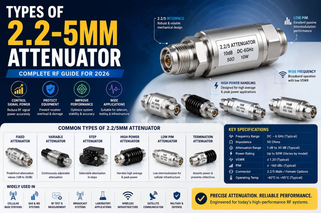
A 2.2-5mm attenuator, commonly written as a 2.2/5 RF attenuator, is a precision RF component used to reduce signal power by a specified amount while maintaining controlled impedance and predictable RF performance. The 2.2/5 interface is a robust coaxial connector technology designed for demanding RF and wireless communication applications.
RF attenuators are essential in systems where signal levels need to be controlled without significantly changing the characteristics of the transmission path. They are widely used in telecommunications, mobile networks, RF testing, measurement systems, base stations, distributed antenna systems, wireless infrastructure, laboratory equipment, and high-power RF applications.
The main types include fixed attenuators, variable attenuators, step attenuators, high-power attenuators, low-PIM attenuators, and termination-style attenuators. Each type is designed for a particular RF requirement.
Understanding attenuation value, frequency range, power rating, VSWR, return loss, PIM performance, connector configuration, and environmental specifications is important when selecting the right 2.2/5 attenuator.
What Is a 2.2/5mm Attenuator?
A 2.2/5mm attenuator is an RF passive device featuring a 2.2/5 coaxial interface and designed to reduce RF signal power by a specified amount.
The term 2.2/5 refers to the connector interface rather than the attenuation value. The connector system uses a 2.2 mm inner contact diameter and 5 mm outer conductor diameter, providing a mechanically robust RF interface suitable for modern wireless infrastructure.
A 2.2/5 attenuator can be manufactured in different attenuation values, such as:
- 1 dB
- 2 dB
- 3 dB
- 5 dB
- 6 dB
- 10 dB
- 15 dB
- 20 dB
- 30 dB
The available values depend on the manufacturer’s design and application requirements.
What Does an RF Attenuator Do?
An RF attenuator reduces the power level of an RF signal by converting a controlled portion of the signal energy into heat.
For example, if a system contains an excessively strong RF signal, an attenuator can reduce the signal before it reaches a sensitive receiver or measurement instrument.
An attenuator can be used to:
- Reduce signal power
- Protect sensitive RF equipment
- Improve impedance matching
- Control signal levels
- Prevent receiver overload
- Simulate cable loss
- Support RF testing
- Improve measurement accuracy
- Balance signal levels in RF networks
How Does a 2.2/5 RF Attenuator Work?
An attenuator uses a resistive or other controlled RF network to introduce a predictable amount of insertion loss.
For a passive attenuator, the attenuation value is expressed in decibels.
The relationship between input and output power is:
Attenuation (dB) = 10 log10(Pin / Pout)
For example, a 10 dB attenuator reduces the output power to approximately one-tenth of the input power.
A 3 dB attenuator reduces power to approximately half, while a 20 dB attenuator reduces power to approximately one-hundredth.
The attenuation network is engineered to maintain the desired characteristic impedance while providing the specified signal reduction.
Why Are 2.2/5 Attenuators Important?
Modern cellular and RF infrastructure often requires components that can operate at relatively high frequencies while maintaining low reflection, reliable mechanical performance, and stable RF characteristics.
A 2.2/5 attenuator can provide controlled signal reduction without requiring changes to the active electronics.
This makes it useful for:
- Cellular base stations
- Distributed antenna systems
- RF laboratories
- Wireless infrastructure
- Test and measurement
- RF distribution networks
- High-power communication systems
Main Types of 2.2/5mm Attenuators
The major types of 2.2/5 RF attenuators include:
- Fixed 2.2/5 Attenuator
- Male-to-Female 2.2/5 Attenuator
- Female-to-Female 2.2/5 Attenuator
- Male-to-Male 2.2/5 Attenuator
- High-Power 2.2/5 Attenuator
- Low-PIM 2.2/5 Attenuator
- Precision 2.2/5 Attenuator
- Step Attenuator
- Variable Attenuator
- Programmable RF Attenuator
- Termination Attenuator
- Broadband 2.2/5 Attenuator
- Outdoor 2.2/5 Attenuator
- Indoor 2.2/5 Attenuator
- Custom 2.2/5 Attenuator
1. Fixed 2.2/5 Attenuator
A fixed 2.2/5 attenuator provides a predetermined attenuation value that cannot be adjusted during operation.
Common values include 3 dB, 6 dB, 10 dB, and 20 dB.
Features
- Fixed attenuation
- Stable RF performance
- Simple installation
- Compact design
- Reliable operation
- No external adjustment required
Applications
Fixed attenuators are commonly used in:
- Cellular infrastructure
- RF test systems
- Base stations
- Distributed antenna systems
- RF cable assemblies
- Signal distribution networks
Fixed attenuators are generally preferred when a specific and permanent signal reduction is required.
2. Male-to-Female 2.2/5 Attenuator
A male-to-female 2.2/5 attenuator contains different connector genders on opposite ends.
This configuration allows the attenuator to be installed directly between compatible RF equipment and cable assemblies without requiring an additional adapter.
Advantages
- Easy installation
- Compact RF connection
- Reduced adapter requirements
- Convenient equipment integration
3. Female-to-Female 2.2/5 Attenuator
A female-to-female attenuator provides two female interfaces.
It can be used where two male RF interfaces need to be connected while introducing a specific attenuation value.
Applications
- RF test benches
- Cellular infrastructure
- Cable assemblies
- RF distribution systems
- Laboratory equipment
4. Male-to-Male 2.2/5 Attenuator
A male-to-male configuration provides male interfaces at both ends.
It can be useful for connecting two female RF interfaces while simultaneously reducing the signal level.
The mechanical configuration should always be checked against the equipment and cable assembly before installation.
5. High-Power 2.2/5 Attenuator
High-power attenuators are designed to handle higher RF power levels than standard low-power attenuators.
When RF power passes through an attenuator, part of the signal energy is dissipated as heat. Therefore, thermal management is a critical aspect of high-power attenuator design.
Important Specifications
- Maximum input power
- Average power rating
- Peak power rating
- Operating temperature
- Thermal resistance
- Frequency range
- VSWR
- Attenuation accuracy
Applications
High-power 2.2/5 attenuators can be used in:
- Base stations
- RF transmitters
- Cellular infrastructure
- Broadcast systems
- RF laboratories
- High-power testing
6. Low-PIM 2.2/5 Attenuator
Low-PIM attenuators are designed for wireless systems where passive intermodulation performance is critical.
PIM, or Passive Intermodulation, occurs when passive RF components generate unwanted mixing products under high RF power conditions.
Low-PIM components are particularly important in cellular networks because unwanted intermodulation products can interfere with receiver performance.
Applications
- Cellular base stations
- Distributed antenna systems
- In-building wireless systems
- Mobile communication infrastructure
- Outdoor wireless networks
Benefits
- Low passive intermodulation
- Reliable cellular performance
- Improved RF network quality
- Suitable for high-power wireless systems
7. Precision 2.2/5 Attenuator
Precision attenuators are designed for applications requiring highly controlled attenuation and excellent RF characteristics.
They may provide tight specifications for:
- Attenuation accuracy
- VSWR
- Return loss
- Insertion loss
- Frequency response
- Connector repeatability
Applications
- RF laboratories
- Network analyzers
- RF calibration
- Measurement systems
- Semiconductor testing
- Communication equipment testing
8. Step 2.2/5 Attenuator
A step attenuator allows the attenuation level to be changed in predefined increments.
For example, a step attenuator may provide selectable values such as:
- 0 dB
- 1 dB
- 2 dB
- 4 dB
- 8 dB
- 10 dB
Different configurations can provide multiple attenuation combinations.
Applications
- RF test equipment
- Signal generators
- Receiver testing
- Transmitter testing
- Laboratory measurements
9. Variable 2.2/5 Attenuator
A variable attenuator allows continuous or controlled adjustment of attenuation.
Unlike a fixed attenuator, the user can change the signal reduction depending on the test or system requirement.
Applications
- RF testing
- Signal conditioning
- Receiver characterization
- Communication system development
- Laboratory research
10. Programmable RF Attenuator
Programmable attenuators allow attenuation to be controlled electronically or through an external control interface.
They are particularly useful in automated RF test systems.
Applications
- Automated test equipment
- RF production testing
- Wireless device testing
- Research laboratories
- Communication system development
Programmable attenuation can be integrated into automated test sequences where signal levels need to be changed repeatedly.
11. Termination-Style 2.2/5 Attenuator
A termination-style attenuator combines signal attenuation with termination functionality.
These components can be used at the end of RF transmission paths to absorb signal energy while providing a controlled impedance.
Applications
- RF test systems
- Unused RF ports
- Signal measurement
- Transmitter testing
- Calibration systems
12. Broadband 2.2/5 Attenuator
A broadband 2.2/5 attenuator is designed to maintain predictable attenuation over a wide frequency range.
Broadband operation is valuable when the same RF infrastructure must support multiple frequencies or communication standards.
Applications
- Multi-band cellular networks
- RF test systems
- Laboratory equipment
- Broadband communication
- Wireless infrastructure
13. Outdoor 2.2/5 Attenuator
Outdoor attenuators are designed to operate in environmental conditions such as:
- Rain
- Humidity
- Dust
- UV exposure
- Temperature variations
- Wind and mechanical stress
Outdoor attenuators may use weather-resistant housings and sealing systems to protect internal RF components.
Applications
- Cellular towers
- Outdoor DAS
- Telecom infrastructure
- Base stations
- Remote wireless installations
14. Indoor 2.2/5 Attenuator
Indoor attenuators are designed for controlled environments such as laboratories, equipment rooms, data centers, RF test facilities, and indoor cellular systems.
They may prioritize compact construction, easy installation, and precision RF performance.
15. Custom 2.2/5 Attenuator
Custom attenuators can be developed according to specific requirements.
Custom parameters may include:
- Frequency range
- Attenuation value
- Power handling
- Connector configuration
- PIM performance
- VSWR
- Return loss
- Mechanical dimensions
- Environmental rating
- Mounting configuration
Custom RF attenuators are useful when standard products cannot meet a particular system requirement.
2.2/5 Attenuator Classification by Attenuation
| Attenuation | Typical Purpose |
|---|---|
| 1 dB | Fine signal adjustment |
| 2 dB | Small signal reduction |
| 3 dB | Moderate power reduction |
| 5 dB | Signal balancing |
| 6 dB | Controlled reduction |
| 10 dB | General signal reduction |
| 15 dB | Higher signal reduction |
| 20 dB | Significant attenuation |
| 30 dB | Strong signal reduction |
The exact attenuation values available depend on the attenuator manufacturer and design.
Understanding Attenuation in dB
The attenuation value describes the ratio between input and output power.
A higher dB value means greater signal reduction.
For example:
| Attenuation | Approximate Output Power |
|---|---|
| 1 dB | 79.4% |
| 3 dB | 50% |
| 6 dB | 25% |
| 10 dB | 10% |
| 20 dB | 1% |
| 30 dB | 0.1% |
These values represent ideal power ratios and do not account for additional system losses.
2.2/5 Attenuator Frequency Range
Frequency range is a critical specification when selecting an attenuator.
The attenuator must be designed to provide the specified attenuation across the intended operating frequencies.
Depending on the product, 2.2/5 attenuators can be designed for cellular and RF applications across various frequency ranges.
Potential applications can include:
- Low-frequency cellular bands
- LTE bands
- Broadband wireless
- RF distribution
- Higher-frequency communication systems
The manufacturer’s datasheet should always be checked for the exact frequency range.
2.2/5 Attenuator Power Rating
Power handling is one of the most important specifications for RF attenuators.
When a signal is attenuated, a portion of the RF energy is dissipated as heat.
For example, a high attenuation value can cause substantial power dissipation inside the component.
The power rating depends on:
- Attenuation value
- Frequency
- Ambient temperature
- Cooling conditions
- Component construction
- Duty cycle
Average vs Peak Power
Some attenuators specify continuous or average power handling, while others may specify peak power capability.
These ratings should not be treated as interchangeable.
Low-PIM Performance in 2.2/5 Attenuators
Low-PIM performance is especially important in cellular infrastructure.
A passive RF network may contain multiple connectors, cables, adapters, splitters, couplers, and attenuators. Any nonlinear passive component can potentially contribute to unwanted intermodulation products.
A low-PIM 2.2/5 attenuator is designed using appropriate materials, surface finishes, mechanical interfaces, and RF construction techniques to minimize passive intermodulation.
VSWR of 2.2/5 Attenuators
VSWR, or Voltage Standing Wave Ratio, indicates the impedance matching between the attenuator and the connected RF system.
A low VSWR generally indicates good impedance matching.
Poor matching can cause:
- Increased reflected power
- Reduced transmission efficiency
- Measurement uncertainty
- Potential degradation of RF system performance
VSWR should be evaluated across the complete operating frequency range.
Return Loss
Return loss describes the amount of RF power reflected back toward the source.
A higher return loss generally corresponds to better impedance matching.
Professional RF attenuator specifications often include return loss or VSWR data to demonstrate the quality of the RF interface.
Insertion Loss
Insertion loss describes the loss introduced by a component when inserted into an RF transmission path.
For an attenuator, the intended attenuation is the dominant signal reduction, but additional insertion-loss effects may also be considered depending on how the device is specified.
In precision applications, attenuation accuracy and frequency response should be evaluated carefully.
2.2/5 Attenuator Connector Configuration
2.2/5 attenuators can be manufactured with different interface configurations.
Common configurations may include:
- Male to Female
- Female to Female
- Male to Male
Connector gender and interface configuration should match the RF equipment and cable assembly.
Why 2.2/5 Connectors Are Used in RF Systems
The 2.2/5 interface was developed for demanding RF applications requiring a robust mechanical connection and reliable electrical performance.
Important characteristics include:
- Robust mechanical construction
- High-frequency capability
- Reliable mating
- Suitable power handling
- Good RF performance
- Application flexibility
These properties make the interface suitable for cellular infrastructure and other RF systems.
Applications of 2.2/5 Attenuators
Cellular Base Stations
Attenuators can be used to control signal levels in RF paths within cellular infrastructure.
Distributed Antenna Systems
DAS installations use attenuators to balance RF signal levels across different branches of a network.
RF Testing
Attenuators are commonly used to control signals entering test equipment.
Network Analyzers
Precision attenuators can help control signal levels during RF measurements.
Signal Generators
Attenuators can reduce the output signal of a generator to a required test level.
Receiver Testing
Attenuators can be used to simulate different signal conditions during receiver sensitivity and performance testing.
Transmitter Testing
High-power attenuators can help safely route transmitter signals into measurement equipment when properly rated.
RF Distribution Systems
Attenuators can help balance signal levels across multiple RF paths.
2.2/5 Attenuators in Cellular Networks
Cellular networks require precise RF signal management.
A network can contain:
- Base station equipment
- Remote radio units
- Antenna systems
- Coaxial cables
- Splitters
- Couplers
- Filters
- Adapters
- Attenuators
Attenuators help manage RF power distribution and prevent excessive signal levels in specific parts of the network.
2.2/5 Attenuators in DAS Systems
Distributed Antenna Systems are designed to distribute cellular signals throughout buildings and large facilities.
Attenuators can be used to balance signal levels between different antenna branches.
They may help prevent one branch from receiving significantly more RF power than another.
Applications include:
- Airports
- Shopping malls
- Hotels
- Stadiums
- Hospitals
- Office buildings
- Transportation facilities
2.2/5 Attenuators for RF Test and Measurement
Test and measurement is one of the most important applications for precision RF attenuators.
They can be used with:
- Vector Network Analyzers
- Spectrum Analyzers
- Signal Generators
- Power Meters
- RF Amplifiers
- Receiver test systems
- Transmitter test systems
Attenuators help create controlled RF signal levels and protect sensitive measurement equipment from excessive input power.
High-Power 2.2/5 Attenuator Thermal Management
Thermal performance is critical in high-power attenuators.
When RF power is dissipated as heat, the component temperature can increase.
Design factors can include:
- Heat-sinking
- Thermal conductivity
- Housing design
- Surface area
- Ambient temperature
- Cooling airflow
For continuous high-power applications, the manufacturer’s power derating curve should be evaluated.
2.2/5 Attenuator Materials
The materials used in an attenuator influence RF performance, durability, and PIM behavior.
Common construction materials may include:
- Brass
- Stainless steel
- Copper
- Aluminum
- PTFE or other dielectric materials
- Precision resistive materials
Surface plating can also influence corrosion resistance, mechanical durability, conductivity, and PIM performance.
2.2/5 Attenuator Durability
RF attenuators used in telecom infrastructure may need to withstand demanding environmental conditions.
Important durability characteristics include:
- Corrosion resistance
- Mechanical strength
- Vibration resistance
- Temperature stability
- Moisture resistance
- UV resistance
- Connector durability
Outdoor products should be selected according to the environmental conditions of the installation.
Indoor vs Outdoor 2.2/5 Attenuators
| Feature | Indoor | Outdoor |
|---|---|---|
| Environment | Controlled | Harsh |
| Weather Protection | Usually limited | Required |
| Moisture Protection | Lower requirement | Important |
| UV Resistance | Usually unnecessary | Important |
| Mounting | Equipment/rack | Pole/tower/wall |
| Typical Application | Labs and DAS | Cellular infrastructure |
Fixed vs Variable 2.2/5 Attenuator
| Feature | Fixed | Variable |
|---|---|---|
| Attenuation | Predetermined | Adjustable |
| Complexity | Low | Higher |
| Installation | Simple | More complex |
| Testing | General | Advanced |
| Cost | Generally lower | Generally higher |
| Application | Permanent signal reduction | RF testing and control |
2.2/5 Attenuator vs Termination
An attenuator and a termination serve different purposes.
An attenuator is designed to reduce the signal level while allowing RF energy to continue through the transmission path.
A termination is primarily designed to absorb RF energy at the end of a transmission line and provide a controlled impedance.
An attenuator can sometimes provide termination functionality depending on its specific design, but the two components should not be considered interchangeable.
2.2/5 Attenuator vs Adapter
An RF adapter changes the physical connector interface between two different RF interfaces.
An attenuator reduces RF signal power.
Therefore:
Adapter = interface conversion
Attenuator = signal-level reduction
A component can combine both functions in specialized designs, but they have fundamentally different purposes.
How to Choose the Right 2.2/5 Attenuator
1. Determine the Required Attenuation
Select the required attenuation value based on the input and desired output signal level.
2. Check Frequency Range
Ensure the attenuator covers the complete operating frequency range.
3. Determine Power Requirements
Calculate the maximum continuous and peak RF power that the attenuator will experience.
4. Check Connector Configuration
Verify whether the application requires male-to-female, female-to-female, or another interface arrangement.
5. Evaluate VSWR
Choose an attenuator with suitable impedance matching over the required frequency range.
6. Consider PIM
For cellular infrastructure, low-PIM performance can be an important selection requirement.
7. Evaluate Environmental Conditions
For outdoor installations, check weather resistance, temperature range, corrosion protection, and sealing.
8. Consider Physical Size
Ensure sufficient clearance is available around the attenuator for installation and thermal management.
9. Check Mechanical Compatibility
Confirm that the connector interface and mounting arrangement are compatible with the existing RF system.
Common Mistakes When Selecting a 2.2/5 Attenuator
Choosing the Wrong Attenuation Value
An incorrect attenuation value can result in excessive signal reduction or insufficient signal control.
Ignoring Power Rating
Using an attenuator beyond its rated power can cause overheating and component failure.
Ignoring Frequency Range
An attenuator should not be used outside its specified frequency range without appropriate engineering validation.
Overlooking PIM
High-PIM components can negatively affect cellular network performance.
Using Poor-Quality Connectors
Connector quality affects RF performance, repeatability, and mechanical reliability.
Ignoring Cable Loss
The attenuator should be evaluated as part of the complete RF transmission path, including cable and connector losses.
Testing 2.2/5 Attenuators
Professional RF testing can include:
- Attenuation measurement
- VSWR measurement
- Return loss
- Insertion loss
- Frequency response
- Power handling
- PIM testing
- Thermal testing
- Mechanical testing
- Environmental testing
A Vector Network Analyzer can be used to characterize RF parameters such as S-parameters, return loss, and insertion loss.
Quality Control for 2.2/5 Attenuators
High-quality attenuators should be manufactured and tested according to controlled production processes.
Important quality-control checks can include:
- Dimensional inspection
- Connector inspection
- RF performance testing
- VSWR testing
- Attenuation accuracy
- Power handling verification
- PIM testing
- Surface finish inspection
- Mechanical durability
Consistent manufacturing is particularly important for components used in cellular networks and precision test equipment.
Future Trends in RF Attenuators
The demand for high-performance RF attenuators continues to grow alongside wireless infrastructure and advanced RF testing.
Important development trends include:
- Higher-frequency attenuators
- Low-PIM designs
- Higher power handling
- Compact RF packages
- Broadband performance
- Improved thermal management
- Precision attenuation
- Automated and programmable attenuation
- Rugged outdoor designs
- Multi-band cellular components
As wireless networks become more complex, RF components must provide predictable performance across wider frequency ranges and increasingly demanding power levels.
2.2/5 Attenuator Selection Checklist
Before purchasing a 2.2/5 attenuator, verify:
| Parameter | Requirement |
|---|---|
| Connector | 2.2/5 |
| Impedance | Typically 50 Ohms |
| Attenuation | Required dB value |
| Frequency | Application-specific |
| Power | Continuous and peak requirements |
| VSWR | Application requirement |
| Return Loss | Required RF performance |
| PIM | Important for cellular systems |
| Connector Gender | Application-specific |
| Environment | Indoor or outdoor |
| Temperature | Required operating range |
| Mounting | Equipment/cable/tower |
| Material | Application-specific |
Conclusion
2.2/5 attenuators are important passive RF components used to control signal levels in cellular infrastructure, RF test equipment, distributed antenna systems, wireless communication networks, and high-power RF applications.
The main types include fixed, variable, step, programmable, precision, high-power, low-PIM, broadband, termination-style, indoor, outdoor, and custom 2.2/5 attenuators.
Selecting the correct attenuator requires more than choosing an attenuation value. Engineers should evaluate frequency range, power handling, VSWR, return loss, PIM performance, connector configuration, thermal requirements, environmental conditions, and mechanical compatibility.
For cellular infrastructure, low-PIM and high-power performance can be particularly important. For RF laboratories, precision attenuation, broadband response, repeatability, and low VSWR may be more important.
A properly specified 2.2/5 attenuator provides controlled RF signal reduction while maintaining reliable transmission-line performance and helping protect sensitive RF equipment.
Frequently Asked Questions
1. What is a 2.2/5 attenuator?
A 2.2/5 attenuator is a passive RF component with a 2.2/5 coaxial interface that reduces RF signal power by a specified amount, such as 3 dB, 6 dB, 10 dB, or 20 dB.
2. What are the main types of 2.2/5 attenuators?
The main types include fixed, variable, step, programmable, precision, high-power, low-PIM, broadband, outdoor, indoor, and termination-style attenuators.
3. What does 2.2/5 mean?
2.2/5 refers to the physical coaxial interface dimensions associated with the connector design. It is not the attenuation value.
4. What attenuation values are available?
Common attenuation values include 1 dB, 2 dB, 3 dB, 5 dB, 6 dB, 10 dB, 15 dB, 20 dB, and 30 dB, although availability varies by product.
5. What is a fixed RF attenuator?
A fixed attenuator provides a predetermined amount of signal attenuation and cannot normally be adjusted during operation.
6. What is a variable RF attenuator?
A variable attenuator allows the amount of RF signal reduction to be adjusted according to system or test requirements.
7. What is a low-PIM 2.2/5 attenuator?
A low-PIM attenuator is designed to minimize passive intermodulation products and is particularly useful in cellular and distributed antenna systems.
8. Why is power rating important in an RF attenuator?
Part of the RF energy entering an attenuator is dissipated as heat. The attenuator must therefore be rated to safely handle the expected continuous and peak RF power.
9. What is the typical impedance of a 2.2/5 attenuator?
2.2/5 RF attenuators are commonly designed for 50-ohm RF systems.
10. What is VSWR in a 2.2/5 attenuator?
VSWR indicates how effectively the attenuator is impedance-matched to the connected RF system. Lower VSWR generally indicates better matching.
11. Where are 2.2/5 attenuators used?
They are used in cellular base stations, DAS systems, RF laboratories, wireless infrastructure, RF distribution networks, transmitters, receivers, and test equipment.
12. Can a 2.2/5 attenuator be used for LTE?
Yes. A suitable 2.2/5 attenuator can be used in LTE systems when its frequency range, power rating, PIM performance, and RF specifications match the application.
13. What is the difference between a 2.2/5 adapter and attenuator?
An adapter changes the connector interface, while an attenuator reduces RF signal power. They perform different functions.
14. What is a high-power 2.2/5 attenuator?
A high-power attenuator is designed to safely dissipate higher levels of RF energy while maintaining its specified RF performance.
15. Why is low-PIM performance important in cellular networks?
Low-PIM performance helps minimize unwanted intermodulation products that can interfere with sensitive cellular receiver systems.
16. Can 2.2/5 attenuators be used outdoors?
Yes. Outdoor-rated 2.2/5 attenuators are designed with suitable environmental protection for applications such as cellular towers and outdoor RF infrastructure.
17. How do I choose a 2.2/5 attenuator?
Consider attenuation value, frequency range, power handling, VSWR, return loss, PIM performance, connector configuration, environmental rating, and mechanical requirements.
18. What is a step attenuator?
A step attenuator provides selectable attenuation levels in predefined increments, making it useful for RF testing and signal-level adjustment.
19. What is a precision RF attenuator?
A precision RF attenuator is designed for highly controlled attenuation accuracy, impedance matching, frequency response, and repeatability, making it suitable for measurement and calibration applications.
20. What is the difference between a 3 dB and 10 dB attenuator?
A 3 dB attenuator reduces power to approximately half of the input power, while a 10 dB attenuator reduces power to approximately one-tenth of the input power.