A 1.0mm attenuator is a precision RF and microwave component designed to reduce signal power by a specified amount while maintaining controlled impedance and predictable electrical performance. These attenuators are commonly used in high-frequency test and measurement systems, semiconductor testing, microwave instrumentation, aerospace and defense equipment, research laboratories, and advanced communication systems.
The 1.0mm coaxial interface is associated with extremely high-frequency applications, making 1.0mm attenuators particularly useful where conventional RF connectors such as SMA, 2.92mm, or 2.4mm may not provide the required frequency capability.
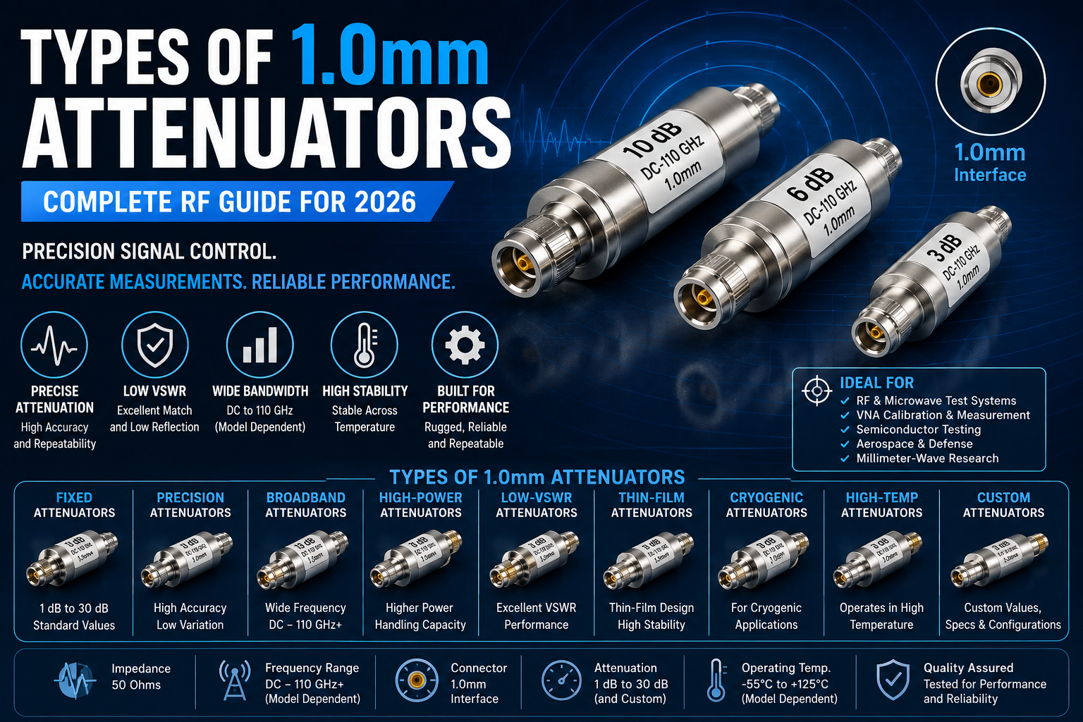
Depending on their design, 1.0mm attenuators can be available as fixed attenuators, precision attenuators, high-power attenuators, low-VSWR attenuators, broadband attenuators, and other specialized configurations.
This guide explains the different types of 1.0mm attenuators, how they work, their construction, specifications, applications, advantages, limitations, testing methods, and important factors to consider when selecting a high-frequency attenuator.
What Is a 1.0mm Attenuator?
A 1.0mm attenuator is a passive RF component with a 1.0mm coaxial interface designed to reduce the amplitude or power level of an RF signal.
An attenuator is normally specified by its attenuation value in decibels, or dB.
Common attenuation values include:
- 1 dB
- 2 dB
- 3 dB
- 6 dB
- 10 dB
- 15 dB
- 20 dB
- 30 dB
The actual available values depend on the attenuator manufacturer and application.
A precision 1.0mm attenuator is designed not only to reduce signal power but also to maintain a controlled impedance, low reflection, predictable insertion loss, and stable RF performance over its specified frequency range.
Why Is the 1.0mm Interface Important?
The 1.0mm connector system is designed for extremely high-frequency coaxial applications.
Its small physical dimensions support applications where wavelength becomes very short and mechanical geometry has a major influence on electrical performance.
1.0mm RF interfaces are commonly associated with millimeter-wave and high-frequency test applications.
The interface is particularly relevant when engineers need:
- Very high operating frequency
- Precision coaxial connections
- Low reflection
- Repeatable RF measurements
- Compact high-frequency components
- High-performance laboratory equipment
How Does a 1.0mm Attenuator Work?
A fixed attenuator uses resistive elements or other engineered RF structures to dissipate a controlled portion of the incoming RF energy.
For example, a 10 dB attenuator reduces the signal power delivered to the output by a factor of 10 under a matched system condition.
The attenuator typically consists of:
- Input connector
- Output connector
- Resistive attenuation network
- Dielectric structure
- Center conductor
- Outer conductor
- Precision mechanical housing
The internal geometry is carefully controlled because even small dimensional variations can influence performance at millimeter-wave frequencies.
Main Types of 1.0mm Attenuators
- Fixed 1.0mm Attenuators
- Precision 1.0mm Attenuators
- Broadband 1.0mm Attenuators
- High-Power 1.0mm Attenuators
- Low-VSWR 1.0mm Attenuators
- Low-Reflection 1.0mm Attenuators
- Thin-Film 1.0mm Attenuators
- Resistive 1.0mm Attenuators
- Calibration-Grade 1.0mm Attenuators
- Cryogenic 1.0mm Attenuators
- High-Temperature 1.0mm Attenuators
- DC-Block-Compatible 1.0mm Attenuator Configurations
- Male-to-Male 1.0mm Attenuators
- Female-to-Female 1.0mm Attenuators
- Male-to-Female 1.0mm Attenuators
- Custom 1.0mm Attenuators
1. Fixed 1.0mm Attenuators
Fixed 1.0mm attenuators provide a predetermined amount of signal attenuation.
They are among the most commonly used attenuator types in RF laboratories and high-frequency systems.
Typical attenuation values can include:
- 1 dB
- 2 dB
- 3 dB
- 6 dB
- 10 dB
- 20 dB
Applications
Fixed 1.0mm attenuators are used in:
- Vector network analyzers
- Signal generators
- Spectrum analyzers
- Microwave test systems
- Semiconductor testing
- RF calibration
- Research laboratories
Advantages
- Simple operation
- High repeatability
- Compact design
- Stable attenuation
- Easy integration
2. Precision 1.0mm Attenuators
Precision attenuators are designed for applications where accurate attenuation and excellent impedance matching are important.
They typically use tightly controlled mechanical and electrical construction to provide predictable performance.
Applications
- Calibration laboratories
- VNA measurements
- RF metrology
- Semiconductor characterization
- Microwave component testing
- Aerospace and defense test systems
Precision attenuators are especially valuable when measurement accuracy is more important than simply reducing signal power.
3. Broadband 1.0mm Attenuators
Broadband 1.0mm attenuators are designed to provide consistent attenuation over a wide frequency range.
Because attenuation characteristics can vary with frequency, broadband designs require careful internal geometry and material selection.
Benefits
- Wide frequency coverage
- Stable attenuation
- Flexible laboratory use
- Reduced need for multiple narrowband attenuators
Applications
- Wideband RF testing
- Millimeter-wave measurement
- Spectrum analysis
- Broadband signal generation
- Research and development
4. High-Power 1.0mm Attenuators
High-power 1.0mm attenuators are designed to handle higher RF power levels than standard precision attenuators.
The primary engineering challenge is thermal management.
The attenuation network converts part of the RF power into heat, which must be safely dissipated.
Important Parameters
- Maximum input power
- Average power
- Peak power
- Pulse width
- Duty cycle
- Temperature rise
- Thermal resistance
High-power capability must always be verified from the manufacturer’s specifications.
5. Low-VSWR 1.0mm Attenuators
Low-VSWR attenuators are designed to provide excellent impedance matching.
VSWR, or Voltage Standing Wave Ratio, indicates how well the RF component is matched to the transmission system.
A low-VSWR attenuator minimizes unwanted reflections and helps maintain measurement accuracy.
Applications
- VNA measurements
- Calibration systems
- High-frequency test fixtures
- Precision microwave measurements
- Semiconductor test systems
6. Low-Reflection 1.0mm Attenuators
Low-reflection attenuators are engineered to provide excellent return loss.
This is important in systems where reflected energy can affect the measurement or operation of sensitive RF components.
Applications
- High-frequency calibration
- Signal conditioning
- RF characterization
- Microwave measurement
- Precision test systems
7. Thin-Film 1.0mm Attenuators
Thin-film technology can be used to manufacture precision resistive elements with tightly controlled electrical characteristics.
Thin-film attenuators can provide:
- High accuracy
- Stable attenuation
- Compact construction
- Good frequency response
- Repeatable electrical performance
They are particularly useful in precision RF and microwave applications.
8. Resistive 1.0mm Attenuators
A resistive attenuator uses a carefully designed resistor network to reduce RF signal power.
Common attenuator topologies include:
- Pi attenuator
- T attenuator
The resistor values are selected according to the required attenuation and system impedance.
In a well-designed RF attenuator, the resistive network must maintain impedance matching while providing the desired attenuation.
9. Calibration-Grade 1.0mm Attenuators
Calibration-grade 1.0mm attenuators are designed for high-accuracy measurement environments.
They are used as known RF standards or signal-conditioning components during calibration and verification procedures.
Applications
- VNA calibration
- Network analyzer verification
- RF metrology
- Measurement laboratories
- High-frequency device characterization
Key Characteristics
- High attenuation accuracy
- Low VSWR
- High return loss
- Excellent repeatability
- Stable performance
- Precise connector interface
10. Cryogenic 1.0mm Attenuators
Cryogenic attenuators are designed for operation at extremely low temperatures.
They are used in specialized research and quantum technology environments where RF components may operate inside cryogenic systems.
Applications
- Quantum computing research
- Cryogenic RF systems
- Low-temperature measurement
- Quantum communication research
- Scientific instrumentation
Cryogenic attenuator designs require careful consideration of thermal conduction, material properties, attenuation stability, and connector performance.
11. High-Temperature 1.0mm Attenuators
High-temperature attenuators are engineered to maintain stable RF performance under elevated temperature conditions.
They may use specialized materials and construction techniques to reduce performance changes caused by thermal expansion and material property variations.
Applications
- Aerospace systems
- Defense electronics
- Industrial RF systems
- High-temperature test environments
- Specialized instrumentation
12. DC-Block-Compatible 1.0mm Attenuator Configurations
Some RF systems require DC isolation between connected components.
In such systems, an attenuator may be combined with a DC-blocking function or used alongside a dedicated DC block.
The exact configuration depends on the system requirements.
Applications
- RF test systems
- Bias-sensitive devices
- Semiconductor measurements
- Microwave instrumentation
- Active RF component testing
Engineers should verify the DC voltage and current ratings before connecting a DC-sensitive attenuator or measurement setup.
13. Male-to-Male 1.0mm Attenuators
A male-to-male attenuator has male 1.0mm interfaces on both ends.
This configuration can be useful when connecting two female RF ports.
Applications
- Test equipment
- RF modules
- VNA setups
- Calibration fixtures
14. Female-to-Female 1.0mm Attenuators
A female-to-female attenuator contains female interfaces on both ends.
It can be used when two male RF connectors need to be connected while introducing a controlled attenuation value.
15. Male-to-Female 1.0mm Attenuators
Male-to-female attenuators combine one male and one female interface.
This configuration can simplify direct connection between equipment with different connector genders.
Benefits
- Flexible installation
- Reduced need for additional adapters
- Compact signal conditioning
- Easy integration into RF test setups
16. Custom 1.0mm Attenuators
Custom attenuators can be designed for specialized applications requiring particular:
- Attenuation values
- Frequency ranges
- Connector configurations
- Power ratings
- Mechanical dimensions
- Environmental specifications
- VSWR requirements
- Return loss
- Temperature ranges
Custom 1.0mm attenuators are useful when standard commercial products do not meet the required RF or mechanical specifications.
1.0mm Attenuator Attenuation Values
Attenuation is measured in decibels.
Common values include:
| Attenuation | Approximate Power Ratio |
|---|---|
| 1 dB | 0.794 |
| 2 dB | 0.631 |
| 3 dB | 0.501 |
| 6 dB | 0.251 |
| 10 dB | 0.100 |
| 15 dB | 0.0316 |
| 20 dB | 0.010 |
| 30 dB | 0.001 |
The power ratio is approximately:
Pout/Pin = 10^(-A/10)
where A represents attenuation in dB.
For example, a 10 dB attenuator allows approximately 10% of the input power to reach the output under matched conditions.
1.0mm Attenuator Frequency Range
The frequency range is one of the most important specifications when selecting a 1.0mm attenuator.
1.0mm coaxial components are intended for extremely high-frequency applications, including millimeter-wave measurement systems.
Depending on the design, specialized 1.0mm attenuators may support frequencies extending into the 100 GHz and beyond range.
The exact maximum frequency should always be verified from the manufacturer’s datasheet because performance depends on the complete connector and attenuator construction.
1.0mm Attenuator Specifications
Important specifications include:
| Parameter | Typical Consideration |
|---|---|
| Connector Interface | 1.0mm |
| Impedance | 50 Ohms |
| Attenuation | 1–30 dB or custom |
| Frequency | Application dependent |
| VSWR | Low for precision applications |
| Return Loss | Application dependent |
| Power Rating | Model dependent |
| Temperature | Application dependent |
| Connector Gender | M-M, F-F, M-F |
| Construction | Precision coaxial |
| Application | RF and microwave |
Actual values should always be obtained from the product datasheet.
1.0mm Attenuator Impedance
Most 1.0mm RF attenuators are designed for a 50-ohm impedance system.
Maintaining 50-ohm impedance throughout the RF signal path is essential for minimizing reflections and maintaining predictable system performance.
Impedance discontinuities can cause:
- Reflections
- Increased VSWR
- Measurement errors
- Reduced power transfer
- Signal distortion
1.0mm Attenuator VSWR
VSWR is particularly important in high-frequency applications because even small impedance discontinuities can become significant at millimeter-wave frequencies.
A low-VSWR attenuator can help minimize reflections between connected RF components.
For precision applications, engineers should evaluate VSWR across the complete operating frequency range instead of relying on a single frequency measurement.
Return Loss of 1.0mm Attenuators
Return loss indicates how much RF energy is reflected back toward the source.
Higher return loss generally indicates better impedance matching.
Return loss is especially important in:
- VNA measurements
- Calibration systems
- Semiconductor testing
- Microwave component characterization
- High-frequency signal chains
Insertion Loss vs Attenuation
Attenuation is the intentional reduction in signal power.
Insertion loss describes the loss introduced by a component when inserted into an RF system.
For an attenuator, the measured insertion loss is related to the specified attenuation but can include additional frequency-dependent effects.
A precision 10 dB attenuator is designed to provide approximately the intended attenuation while maintaining acceptable impedance matching and frequency response.
1.0mm Attenuator Power Handling
Power handling is a critical parameter when selecting an attenuator.
The actual power capability depends on:
- Attenuation value
- Frequency
- Internal resistor technology
- Thermal design
- Ambient temperature
- Duty cycle
- Connector construction
A high-frequency attenuator should never be operated above its specified power rating.
Peak Power vs Average Power
RF attenuator specifications may distinguish between peak and average power.
Average Power
Average power represents the continuous thermal load experienced by the attenuator.
Peak Power
Peak power represents short-duration RF power that the attenuator can withstand under specified conditions.
Pulse width, repetition rate, and duty cycle can significantly affect allowable power.
Applications of 1.0mm Attenuators
1.0mm attenuators are used in many advanced RF and microwave applications.
RF Test and Measurement
They are used for controlling signal levels between:
- Signal generators
- Spectrum analyzers
- VNAs
- Power meters
- RF receivers
Semiconductor Testing
High-frequency semiconductor devices require controlled RF signal levels during characterization.
1.0mm attenuators can be used in test fixtures and measurement paths for high-frequency devices.
Aerospace and Defense
Advanced radar, electronic warfare, communication, and RF test systems can require precision high-frequency attenuators.
Millimeter-Wave Research
Research laboratories use 1.0mm components in experimental millimeter-wave systems.
Calibration Systems
Precision attenuators can provide known signal reduction during RF calibration and verification.
Microwave Instrumentation
High-frequency measurement equipment can use 1.0mm attenuators for signal conditioning and level control.
Antenna Testing
Attenuators can help control RF power levels during antenna and wireless system measurements.
RF Signal Conditioning
An attenuator can be inserted into an RF signal path to prevent excessive input power from reaching sensitive equipment.
1.0mm Attenuators for VNA Applications
Vector Network Analyzers are highly sensitive measurement instruments used to characterize RF components.
1.0mm attenuators can be used in VNA setups for:
- Signal level control
- Calibration
- Protection
- Port matching
- Measurement repeatability
- Device characterization
The attenuator’s frequency range and connector interface must match the VNA and associated test components.
1.0mm Attenuators for Semiconductor Testing
As semiconductor technology moves toward higher frequencies, accurate RF measurements become increasingly important.
1.0mm attenuators can be used for testing:
- RF integrated circuits
- Millimeter-wave amplifiers
- Mixers
- Filters
- Oscillators
- Transceiver modules
- High-frequency switches
The attenuator helps establish a controlled signal environment around the device under test.
1.0mm Attenuators for Aerospace and Defense
Aerospace and defense systems often require high-frequency RF components with stable electrical and mechanical performance.
Applications can include:
- Radar testing
- RF front-end testing
- Electronic warfare test systems
- Satellite communication equipment
- Microwave instrumentation
- Antenna measurement systems
For these applications, engineers may prioritize:
- Low VSWR
- High return loss
- Repeatability
- Temperature stability
- Mechanical reliability
- High-frequency performance
1.0mm Attenuator Materials and Construction
High-frequency attenuators require precision manufacturing because the physical dimensions of the RF path directly affect electrical performance.
Typical construction considerations include:
- Precision-machined metal bodies
- High-quality coaxial interfaces
- Controlled dielectric materials
- Precision resistive elements
- Plated contact surfaces
- Robust connector structures
Material selection influences:
- RF loss
- Thermal performance
- Mechanical stability
- Corrosion resistance
- Frequency response
Advantages of 1.0mm Attenuators
Extremely High-Frequency Capability
1.0mm interfaces are designed for demanding high-frequency and millimeter-wave applications.
Precision RF Performance
Precision mechanical construction supports controlled electrical characteristics.
Compact Size
The small connector interface is useful in dense high-frequency test systems.
Controlled Signal Levels
Attenuators allow engineers to reduce RF signal levels without redesigning the entire signal chain.
Improved Measurement Protection
An attenuator can help protect sensitive RF inputs when properly selected and operated.
Excellent Integration
1.0mm attenuators can be integrated into precision coaxial test setups and high-frequency instrumentation.
Limitations of 1.0mm Attenuators
Higher Cost
Precision millimeter-wave components can be more expensive than lower-frequency RF attenuators.
Mechanical Sensitivity
Small high-frequency interfaces require careful handling.
Connector Wear
Repeated mating and unmating can affect connector performance.
Limited Power Handling
High-frequency precision attenuators may have lower power ratings than larger low-frequency attenuators.
Installation Requirements
Proper torque, cleanliness, alignment, and connector care are important for maintaining performance.
1.0mm Connector Handling
Because 1.0mm interfaces are precision components, proper handling is essential.
Important practices include:
- Keep connectors clean
- Avoid touching contact surfaces
- Use protective caps when not in use
- Avoid cross-threading
- Align connectors carefully
- Use the manufacturer’s recommended torque
- Avoid excessive mechanical force
- Inspect connectors before mating
Proper connector handling can significantly improve measurement repeatability and component life.
1.0mm Attenuator Testing
Professional testing may include:
- S-parameter measurement
- Insertion loss measurement
- Return loss measurement
- VSWR measurement
- Attenuation accuracy
- Power handling
- Temperature testing
- Mechanical inspection
A calibrated Vector Network Analyzer can be used to characterize high-frequency attenuator performance.
S-Parameters of 1.0mm Attenuators
S-parameters are widely used to characterize RF components.
Important parameters include:
S11
S11 represents input reflection characteristics.
S21
S21 represents forward transmission characteristics.
S12
S12 represents reverse transmission.
S22
S22 represents output reflection.
For a well-designed fixed attenuator, engineers generally expect controlled transmission attenuation and low reflections over the specified operating range.
1.0mm Attenuator Calibration
Calibration is essential for accurate high-frequency measurements.
Depending on the measurement setup, calibration techniques may include:
- SOLT
- TRL
- LRM
- Other VNA calibration methods
The appropriate method depends on frequency, connector interface, measurement architecture, and calibration standards.
1.0mm Attenuator vs 2.4mm Attenuator
| Feature | 1.0mm | 2.4mm |
|---|---|---|
| Physical Interface | Smaller | Larger |
| Frequency Capability | Extremely high | Very high |
| Typical Use | Millimeter-wave | Microwave/mmWave |
| Mechanical Sensitivity | Higher | Moderate |
| Application | Advanced test systems | RF/microwave testing |
| Cost | Generally higher | Generally lower |
The exact frequency capabilities depend on the individual component design.
1.0mm Attenuator vs 2.92mm Attenuator
| Feature | 1.0mm | 2.92mm |
|---|---|---|
| Interface Size | Very small | Larger |
| Frequency Range | Higher-frequency applications | Commonly up to mmWave ranges |
| Typical Use | Advanced mmWave | RF and microwave testing |
| Mechanical Robustness | More delicate | More robust |
| Application | Precision high-frequency measurement | General microwave testing |
How to Select the Right 1.0mm Attenuator
1. Determine the Required Attenuation
Select the attenuation value required by the RF system.
2. Determine the Frequency Range
Make sure the attenuator supports the complete operating frequency.
3. Check Impedance
Confirm that the attenuator matches the system impedance, normally 50 ohms.
4. Check VSWR
Select a low-VSWR design for precision measurements.
5. Evaluate Return Loss
High return loss is desirable when reflections must be minimized.
6. Check Power Handling
Determine both average and peak RF power requirements.
7. Select Connector Gender
Choose:
- Male-to-male
- Female-to-female
- Male-to-female
according to the equipment interfaces.
8. Check Mechanical Dimensions
Ensure sufficient clearance in the test fixture or RF system.
9. Consider Temperature
For demanding applications, evaluate operating temperature and temperature stability.
10. Verify Calibration Requirements
For precision measurement, select a component with appropriate characterization and calibration data.
Common Mistakes When Selecting 1.0mm Attenuators
Choosing Only by Attenuation Value
A 10 dB attenuator is not automatically suitable for every 10 dB application. Frequency, VSWR, power handling, and connector quality also matter.
Ignoring Frequency
The attenuation value may be correct while the frequency range is unsuitable.
Ignoring Connector Compatibility
The attenuator must mechanically and electrically match the connected equipment.
Exceeding Power Rating
Excessive RF power can permanently damage the internal attenuation network.
Poor Connector Handling
Contamination or mechanical damage can degrade high-frequency performance.
Using Incompatible Calibration Standards
Calibration accuracy depends on using appropriate standards and procedures.
Best Practices for 1.0mm Attenuator Installation
- Verify the RF frequency range.
- Confirm 50-ohm impedance.
- Inspect connectors before use.
- Keep mating surfaces clean.
- Use appropriate torque.
- Avoid side loading.
- Use compatible cables.
- Minimize unnecessary adapters.
- Check power levels before connection.
- Perform VNA verification when measurement accuracy is critical.
Future Trends in 1.0mm Attenuator Technology
The increasing demand for millimeter-wave and sub-terahertz research is driving the development of more advanced high-frequency RF components.
Important trends include:
- Higher operating frequencies
- Improved attenuation accuracy
- Lower VSWR
- Better connector repeatability
- Higher thermal stability
- Cryogenic RF components
- More compact test fixtures
- Improved calibration standards
- Advanced semiconductor testing
- High-frequency 6G research
- Sub-terahertz instrumentation
As RF systems move toward higher frequencies, precision attenuators will remain important components for signal conditioning, calibration, measurement, and protection.
Conclusion
1.0mm attenuators are precision RF components designed for demanding high-frequency and millimeter-wave applications. Their compact coaxial interface, controlled attenuation, and potential for excellent impedance matching make them valuable in advanced RF test and measurement systems.
The major types include fixed, precision, broadband, high-power, low-VSWR, low-reflection, thin-film, calibration-grade, cryogenic, high-temperature, and custom 1.0mm attenuators.
When selecting a 1.0mm attenuator, engineers should evaluate attenuation value, frequency range, impedance, VSWR, return loss, power handling, connector gender, mechanical construction, operating temperature, and calibration requirements.
For applications involving VNAs, semiconductor characterization, aerospace and defense testing, millimeter-wave research, antenna testing, and advanced RF instrumentation, choosing a properly specified 1.0mm attenuator is essential for maintaining reliable and repeatable measurement performance.
Frequently Asked Questions
1. What is a 1.0mm attenuator?
A 1.0mm attenuator is a precision RF component with a 1.0mm coaxial interface that reduces an RF signal by a specified amount while maintaining controlled impedance and predictable high-frequency performance.
2. What are the main types of 1.0mm attenuators?
Common types include fixed, precision, broadband, high-power, low-VSWR, low-reflection, thin-film, calibration-grade, cryogenic, high-temperature, and custom 1.0mm attenuators.
3. What is a fixed 1.0mm attenuator?
A fixed 1.0mm attenuator provides a predetermined attenuation value, such as 3 dB, 6 dB, 10 dB, or 20 dB, and is commonly used for signal conditioning and RF testing.
4. What is the purpose of a 1.0mm attenuator?
A 1.0mm attenuator reduces RF signal power to a controlled level and can be used for signal conditioning, equipment protection, calibration, impedance control, and high-frequency measurements.
5. What frequency range does a 1.0mm attenuator support?
The frequency range depends on the specific product. 1.0mm coaxial components are designed for extremely high-frequency applications, including millimeter-wave systems, with some specialized products extending to 100 GHz and beyond.
6. What impedance do 1.0mm attenuators use?
Most 1.0mm RF attenuators are designed for a nominal 50-ohm system.
7. What attenuation values are available?
Common values include 1 dB, 2 dB, 3 dB, 6 dB, 10 dB, 15 dB, 20 dB, and 30 dB, although custom attenuation values may also be available.
8. What is the difference between attenuation and insertion loss?
Attenuation is the intentional reduction of RF signal power provided by an attenuator. Insertion loss describes the loss introduced by a component when it is inserted into an RF system and can include additional frequency-dependent effects.
9. Why is VSWR important in a 1.0mm attenuator?
VSWR indicates impedance matching. A low-VSWR attenuator minimizes reflections and can improve measurement accuracy in high-frequency RF systems.
10. What is a high-power 1.0mm attenuator?
A high-power 1.0mm attenuator is designed to handle higher RF power while safely dissipating the heat generated by the attenuation network.
11. What is a precision 1.0mm attenuator?
A precision 1.0mm attenuator is manufactured to provide highly controlled attenuation, low reflection, and repeatable electrical performance for measurement and calibration applications.
12. Where are 1.0mm attenuators used?
They are used in RF test and measurement, semiconductor testing, VNA systems, microwave instrumentation, aerospace and defense, millimeter-wave research, antenna testing, and advanced communication equipment.
13. Can a 1.0mm attenuator be used with a VNA?
Yes. 1.0mm attenuators can be used in compatible VNA systems for signal conditioning, calibration, protection, and measurement applications.
14. What is a cryogenic 1.0mm attenuator?
A cryogenic 1.0mm attenuator is designed to operate at very low temperatures and can be used in specialized systems such as quantum research and cryogenic RF measurement setups.
15. What is a broadband 1.0mm attenuator?
A broadband 1.0mm attenuator is designed to maintain controlled attenuation across a wide frequency range, reducing the need for multiple narrowband attenuators.
16. What is the difference between a 1.0mm and 2.4mm attenuator?
The 1.0mm interface is smaller and is intended for extremely high-frequency applications, while 2.4mm components are larger and are widely used in microwave and millimeter-wave systems.
17. What connectors are available for 1.0mm attenuators?
1.0mm attenuators can be manufactured with different gender configurations, including male-to-male, female-to-female, and male-to-female interfaces.
18. Can a 1.0mm attenuator handle high RF power?
Some specialized 1.0mm attenuators are designed for higher power, but power capability is product-specific and decreases or changes depending on frequency, temperature, duty cycle, and attenuation value.
19. How should a 1.0mm attenuator be handled?
Keep the connectors clean, protect them with caps when not in use, align mating interfaces carefully, avoid cross-threading, and use the manufacturer’s recommended mating torque.
20. How do I choose the right 1.0mm attenuator?
Consider attenuation value, frequency range, impedance, VSWR, return loss, power handling, connector configuration, temperature range, mechanical requirements, and calibration needs before selecting a 1.0mm attenuator.