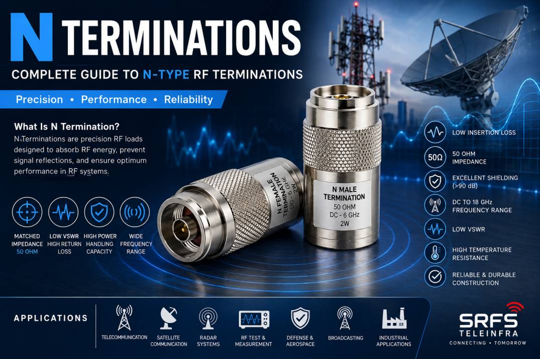
N Terminations are precision RF components designed to terminate unused ports, transmission lines, antennas, RF systems, and test equipment with a controlled impedance. They are commonly used with N Type connectors in telecommunications, wireless communication, RF testing, broadcasting, radar, defense, and microwave applications.
The primary purpose of an N Termination is to absorb RF energy and prevent unwanted signal reflections. In a properly designed RF system, an unterminated or improperly terminated port can create impedance mismatch, resulting in reflected power, standing waves, signal distortion, and reduced system performance.
N Terminations are typically designed for 50 Ohm RF systems and are available in different frequency, power-handling, connector-gender, and environmental configurations. They are particularly useful in RF test setups where unused ports must be terminated with a known impedance.
What Is an N Termination?
An N Termination is an RF termination fitted with an N Type connector interface and an internal resistive element designed to present a controlled impedance to an RF transmission system.
In a typical 50 Ohm RF system, the termination provides a load that closely matches the characteristic impedance of the connected transmission line. When RF energy reaches the termination, the internal resistive element absorbs the energy instead of reflecting a significant portion of it back toward the source.
N Terminations can be supplied in male or female configurations depending on the equipment and connection requirements.
They are commonly used for:
RF test equipment
RF amplifiers
Antennas
Coaxial transmission lines
Base station systems
Telecommunication infrastructure
Wireless networks
Radar systems
Satellite communication
Broadcasting systems
Laboratory RF measurements
How Does an N Termination Work?
The fundamental function of an N Termination is impedance matching.
RF transmission systems are designed around a specific characteristic impedance, commonly 50 Ohms. When the load connected to the transmission line also presents approximately 50 Ohms, maximum power transfer can occur with minimal reflection.
An N Termination contains a precision resistive load that converts incoming RF energy into heat.
The basic operating sequence is:
RF signal travels through the coaxial cable.
The signal reaches the N Type connector.
The RF energy enters the termination circuit.
The internal resistive element absorbs the RF power.
Only a very small amount of energy is reflected back.
The transmission line therefore sees a matched load.
This helps maintain stable RF system performance.
Why Are N Terminations Important in RF Systems?
RF signals are highly sensitive to impedance mismatches. When an RF port is left open or connected to an unsuitable load, part of the signal can be reflected.
These reflections can cause:
High VSWR
Return loss degradation
Insertion loss variations
Signal distortion
Standing waves
Power instability
Measurement errors
Potential stress on RF amplifiers
N Terminations provide a controlled load that minimizes these problems.
For this reason, they are essential accessories in RF laboratories, telecom installations, antenna systems, and RF testing environments.
N Termination and 50 Ohm Impedance
Most N Terminations used for telecommunications and RF applications are designed around 50 Ohm impedance.
The impedance of the termination should match the characteristic impedance of the connected RF system.
For example, a 50 Ohm N Termination is appropriate for a 50 Ohm coaxial transmission line.
Maintaining impedance consistency throughout an RF system helps minimize signal reflections and maintain predictable RF performance.
N Male Termination
An N Male Termination features a male N Type connector interface.
It is commonly used when the RF equipment, cable, or port has an N Female interface.
Typical applications include:
RF equipment outputs
Antenna systems
Coaxial cable testing
RF amplifiers
Telecom equipment
Test benches
Outdoor RF installations
N Female Termination
An N Female Termination features a female N Type connector interface.
It is generally used with N Male RF connectors.
N Female Terminations are frequently used for terminating:
RF equipment ports
Antenna ports
Coaxial cables
RF test fixtures
Signal distribution systems
Telecommunication equipment
Key Features of N Terminations
50 Ohm Impedance
N Terminations for RF applications are commonly manufactured with a 50 Ohm impedance to match standard RF transmission systems.
Low VSWR
A good-quality RF termination provides low VSWR across its specified frequency range, reducing unwanted reflections.
High Return Loss
High return loss indicates that only a small amount of RF energy is reflected toward the source.
Wide Frequency Range
N Terminations are available for different RF frequency requirements. The applicable frequency range depends on the design, connector construction, and internal resistive element.
Power Handling Capability
Different N Terminations are designed for different RF power levels. Low-power versions are commonly used for laboratory testing, while high-power versions can be designed for transmitters and telecom applications.
Robust Construction
N Type connectors are known for their mechanically robust construction, making them suitable for demanding RF and telecom environments.
Environmental Protection
Outdoor versions can be designed with weather-resistant construction for applications involving moisture, dust, temperature changes, and outdoor exposure.
Reliable RF Performance
Precision manufacturing helps maintain stable electrical characteristics and repeatable performance across the operating frequency range.
Types of N Terminations
N Terminations can be classified according to connector gender, power rating, frequency range, and application.
Standard N Termination
Standard N Terminations are used for general-purpose RF applications and laboratory testing.
High-Power N Termination
High-power N Terminations are designed to dissipate larger amounts of RF energy. They may incorporate enhanced thermal management and larger resistive structures.
These are suitable for:
RF transmitters
Base stations
Broadcasting
Antenna testing
Telecom infrastructure
Power amplifier testing
Low-Power N Termination
Low-power terminations are commonly used with RF test instruments, signal generators, network analyzers, and laboratory equipment.
Outdoor N Termination
Outdoor N Terminations are designed for applications where the component may be exposed to environmental conditions.
They may incorporate weather-resistant sealing and corrosion-resistant materials.
Precision N Termination
Precision N Terminations are designed for applications requiring highly controlled RF characteristics, particularly laboratory measurements and calibration.
N Terminations vs N Loads
The terms N Termination and N Load are often used interchangeably.
An N Load is essentially a matched RF load using an N Type connector.
An N Termination is generally described according to its function of terminating an RF port or transmission line.
In practical RF applications, both can provide a controlled impedance load when correctly specified.
N Termination vs 50 Ohm Dummy Load
An N Termination can be considered a type of RF dummy load when it is used to absorb RF power instead of transmitting it onward.
However, a high-power dummy load may be designed specifically for substantial continuous RF power dissipation, whereas a small N Termination may primarily be intended for signal-level testing.
Therefore, the power rating should always be checked before connecting an N Termination to a transmitter or high-power RF source.
Electrical Specifications of N Terminations
Important specifications to consider include:
Impedance
Frequency range
VSWR
Return loss
Power rating
Connector type
Connector gender
Insertion characteristics
Operating temperature
Maximum operating voltage
Environmental rating
Connector plating
Material construction
The exact specifications depend on the manufacturer and product series.
Mechanical Construction of N Terminations
A typical N Termination consists of several important components.
N Type Connector
The connector provides the mechanical and electrical interface with the RF equipment or coaxial cable.
Center Conductor
The center conductor carries RF energy into the termination.
Dielectric
The dielectric maintains the required spacing between the center and outer conductors while controlling the RF characteristics.
Outer Conductor
The outer conductor provides the return path and shielding.
Resistive Element
The internal resistive element absorbs the RF energy and provides the required impedance.
Housing
The external housing protects the internal components and provides mechanical strength.
Materials Used in N Terminations
High-quality N Terminations may use materials such as:
Brass
Stainless steel
Copper alloys
PTFE dielectric materials
Precision RF resistive elements
Nickel or gold plating
The material selection depends on frequency, power, environmental requirements, durability, and manufacturing design.
Applications of N Terminations
Telecommunications
N Terminations are widely used in telecom infrastructure for terminating unused RF ports and testing RF transmission systems.
Base Station Systems
They can be used during installation, commissioning, maintenance, and troubleshooting of wireless base station equipment.
RF Testing
RF laboratories use N Terminations with signal generators, spectrum analyzers, network analyzers, amplifiers, and other RF instruments.
Antenna Testing
Unused antenna ports can be terminated using appropriate N Terminations during testing and measurement.
Radar Systems
Radar systems require controlled RF loads during testing and calibration.
Defense and Aerospace
Precision RF terminations can be used in communication, radar, electronic warfare testing, and RF measurement systems.
Broadcasting
RF termination loads can be used in transmitter testing, signal distribution systems, and RF infrastructure.
Satellite Communication
N Terminations can be used in satellite communication equipment and RF test setups where compatible N interfaces are required.
Wireless Networks
They can be used in RF distribution systems, DAS installations, wireless infrastructure, and network commissioning.
N Terminations in RF Testing
N Terminations are especially important in RF testing because measurement accuracy depends on controlled impedance conditions.
For example, during an RF test, an unused output port may need to be terminated with a matched load.
Using an appropriate N Termination helps prevent the unused port from becoming an unintended signal reflection point.
This is particularly important when working with:
Vector Network Analyzers
Spectrum Analyzers
Signal Generators
RF Power Amplifiers
Antenna Test Systems
RF Switches
Couplers
Power Dividers
Combiners
N Terminations and VSWR
VSWR, or Voltage Standing Wave Ratio, is an important parameter when evaluating an RF termination.
A perfect matched termination would theoretically provide a VSWR of 1:1.
In practical applications, the VSWR will be slightly higher because of connector tolerances, resistive element characteristics, manufacturing variations, and frequency-dependent effects.
Lower VSWR generally indicates better impedance matching.
N Terminations and Return Loss
Return loss measures how much RF power is reflected back toward the source.
A higher return-loss value generally indicates better matching.
For precision RF applications, both VSWR and return loss should be considered when selecting an N Termination.
Power Rating of N Terminations
Power handling is one of the most important specifications.
A termination must be selected according to the RF power that it will dissipate.
For example, a low-power laboratory termination should not be connected directly to a high-power RF transmitter unless its power rating specifically supports that application.
Exceeding the rated power can cause:
Excessive heating
Resistive element failure
Connector damage
Permanent performance degradation
Potential RF equipment damage
Always verify both continuous-wave and peak power ratings where applicable.
Frequency Selection
The N Termination should be selected according to the operating frequency of the RF system.
At higher frequencies, connector geometry, dimensional tolerances, dielectric properties, and internal construction become increasingly important.
A termination designed for a lower frequency range should not automatically be assumed to perform correctly at microwave frequencies.
How to Select the Right N Termination
When selecting an N Termination, consider the following parameters.
1. Impedance
Select the correct impedance, typically 50 Ohms for RF telecom applications.
2. Frequency
Ensure that the termination’s specified frequency range covers the complete operating range of the system.
3. Power
Select a termination with sufficient continuous and peak power capability.
4. Connector Gender
Choose N Male or N Female according to the mating RF interface.
5. VSWR
Select a low-VSWR termination for applications where signal reflection must be minimized.
6. Return Loss
Higher return loss is generally preferred for precision RF applications.
7. Environmental Conditions
For outdoor applications, consider sealing, corrosion resistance, temperature range, and environmental protection.
8. Mechanical Requirements
Check connector dimensions, mounting requirements, mating compatibility, and mechanical durability.
Advantages of N Terminations
N Terminations offer several advantages in RF systems.
They provide controlled impedance.
They reduce unwanted RF reflections.
They help maintain low VSWR.
They protect unused RF ports.
They support reliable RF testing.
They are available in multiple power ratings.
They offer robust mechanical construction.
They are suitable for telecom and wireless infrastructure.
They can be used in indoor and outdoor applications.
They are available in precision configurations for laboratory measurements.
Common Mistakes When Using N Terminations
Using the Wrong Impedance
Connecting a 75 Ohm termination to a 50 Ohm RF system can result in impedance mismatch.
Exceeding the Power Rating
Applying excessive RF power can damage the termination.
Ignoring Frequency Limits
A termination may not provide the expected performance outside its specified frequency range.
Poor Connector Mating
Improperly tightened or damaged connectors can affect RF performance.
Using Damaged Terminations
Physical damage, contamination, or worn connector interfaces can increase reflections.
Selecting Only by Connector Type
An N connector alone does not determine whether the termination is suitable. Frequency, power, VSWR, return loss, and environmental specifications must also be considered.
Maintenance of N Terminations
Proper maintenance can improve reliability and service life.
Keep connector interfaces clean.
Avoid excessive mechanical force.
Inspect the connector for damage.
Protect unused terminations from contamination.
Avoid exceeding the rated RF power.
Store components in a clean and dry environment.
Use appropriate torque when mating RF connectors.
Inspect outdoor components for corrosion or seal degradation.
N Terminations for Telecom Infrastructure
Modern telecom networks require reliable RF components for installation, testing, and maintenance.
N Terminations can be used in:
4G infrastructure
5G infrastructure
Base stations
RF feeder systems
DAS networks
Antenna systems
RF distribution networks
Telecom testing
Network commissioning
Their robust connector construction makes N Type terminations suitable for demanding telecom environments.
N Terminations for 4G and 5G Networks
4G and 5G infrastructure uses a wide range of RF components, including cables, connectors, adapters, combiners, splitters, antennas, and terminations.
N Terminations can be used during installation and testing to provide a known RF load on unused interfaces.
For higher-frequency 5G applications, it is particularly important to verify the termination’s frequency specification and RF performance.
Why Choose High-Quality N Terminations?
RF systems operate within precise electrical parameters. A poor-quality termination can introduce additional reflection, loss, and measurement uncertainty.
A high-quality N Termination should provide:
Consistent impedance
Precision connector geometry
Reliable RF performance
Stable electrical characteristics
Good mechanical strength
Appropriate power handling
Reliable environmental performance
Repeatable manufacturing quality
For critical RF applications, product specifications and test data should be reviewed before selection.
N Terminations from SRFS Teleinfra
SRFS Teleinfra provides RF and telecom infrastructure components designed for professional RF, wireless, and telecommunications applications.
Its RF product portfolio includes connectors, cable assemblies, RF adapters, termination solutions, telecom accessories, grounding products, weatherproofing products, and other RF infrastructure components.
For N Terminations, the appropriate configuration should be selected according to impedance, frequency range, power rating, connector gender, VSWR, return loss, and environmental requirements.
SRFS Teleinfra focuses on supplying RF components suitable for telecom infrastructure, RF testing, wireless networks, and related industrial applications.
Frequently Asked Questions About N Terminations
What is an N Termination?
An N Termination is an RF load with an N Type connector designed to provide a controlled impedance and absorb RF energy while minimizing signal reflections.
What impedance is commonly used for N Terminations?
50 Ohms is the most common impedance for N Terminations used in RF, telecom, wireless, and test applications.
What is the purpose of an N Termination?
Its primary purpose is to terminate an RF port with a matched load, reducing reflections and helping maintain proper RF system performance.
Are N Terminations available in male and female versions?
Yes. N Terminations are available with N Male and N Female connector interfaces to match different RF equipment and cable configurations.
Can an N Termination be used for 5G?
Yes, provided that its frequency range, impedance, VSWR, power rating, and connector specifications are suitable for the particular 5G application.
Can an N Termination handle high RF power?
Some N Terminations are specifically designed for high-power applications. The manufacturer’s continuous and peak power ratings must be checked before use.
What is the difference between an N Termination and an N Adapter?
An N Adapter connects two different RF interfaces or connector genders, whereas an N Termination provides a matched RF load and absorbs RF energy.
Why is 50 Ohm matching important?
50 Ohm matching minimizes impedance mismatch and reduces reflected RF energy, helping maintain stable signal transmission and measurement accuracy.
Where are N Terminations used?
They are used in telecom networks, RF laboratories, antenna systems, base stations, radar, defense, aerospace, broadcasting, satellite communication, and wireless infrastructure.
How do I choose an N Termination?
Consider impedance, frequency range, power rating, connector gender, VSWR, return loss, environmental conditions, and mechanical requirements before selecting the product.
Conclusion
N Terminations are essential RF components for maintaining controlled impedance and minimizing unwanted signal reflections. By providing a matched load, they help protect RF systems, improve measurement accuracy, and maintain reliable performance.
From telecom base stations and 4G/5G infrastructure to RF laboratories, antenna testing, radar, aerospace, defense, and broadcasting, N Terminations are used wherever unused RF ports or transmission lines require a reliable matched load.
Selecting the correct N Termination requires careful consideration of impedance, frequency, power handling, VSWR, return loss, connector gender, and environmental requirements. A properly specified termination can significantly contribute to the reliability and stability of an RF system.