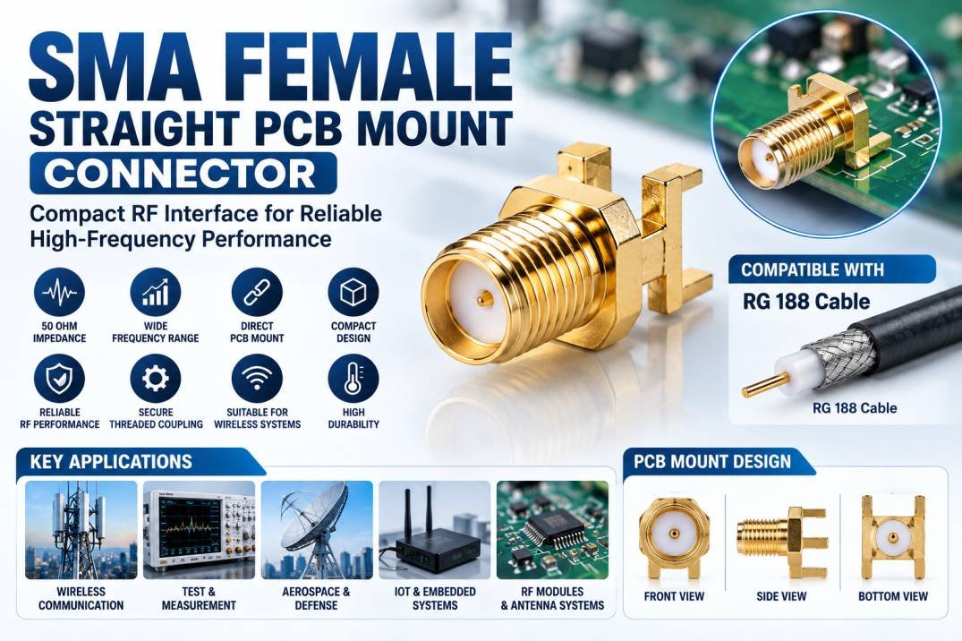
An SMA Female Straight PCB Mount Connector is a compact RF connector designed to provide a reliable coaxial connection between a printed circuit board (PCB) and an external RF cable or device. SMA connectors are widely used in RF, microwave, wireless communication, test and measurement, aerospace, defense, and electronic equipment because of their compact size and dependable high-frequency performance.
The straight PCB mount configuration is designed to be mounted directly onto a circuit board, creating a stable RF interface while saving space inside compact electronic systems. The female SMA interface is commonly paired with an SMA male connector or compatible RF cable assembly.
What Is an SMA Female Straight PCB Mount Connector?
An SMA Female Straight PCB Mount Connector consists of a female SMA interface and a PCB mounting structure arranged in a straight configuration. The connector provides a controlled RF transition between the transmission line on the PCB and an external coaxial connection.
Unlike cable-mounted SMA connectors, PCB mount versions are directly installed on the circuit board. This makes them useful for RF modules, communication equipment, antennas, wireless systems, and laboratory instruments where the RF interface needs to be integrated directly into the enclosure or PCB.
The connector is generally designed around a 50-ohm RF impedance, making it suitable for many RF and microwave applications.
Construction of SMA Female Straight PCB Mount Connector
The construction of an SMA Female Straight PCB Mount Connector typically includes several important components:
SMA Female Interface
The female SMA interface provides the mating point for an SMA male connector. Its threaded coupling mechanism helps provide secure mechanical attachment and consistent RF contact.
Center Contact
The center contact carries the RF signal between the PCB transmission line and the connected coaxial interface. Proper contact geometry is important for maintaining signal integrity.
Insulator
An insulating material separates the center contact from the outer conductor while maintaining the required electrical characteristics of the connector.
Outer Conductor
The outer conductor provides shielding and serves as the RF return path. It also helps reduce unwanted electromagnetic interference and signal leakage.
PCB Mounting Section
The PCB mounting structure allows the connector to be mechanically and electrically integrated with the circuit board. Depending on the design, mounting may use PCB solder connections and additional mechanical support features.
Key Features of SMA Female Straight PCB Mount Connector
The SMA Female Straight PCB Mount Connector offers several features that make it suitable for compact RF systems:
- Female SMA interface
- Straight PCB mounting configuration
- Compact RF connector design
- Typically 50-ohm impedance
- Secure threaded coupling
- Direct PCB integration
- Suitable for RF and microwave applications
- Reliable mechanical connection
- Good shielding performance
- Suitable for compact electronic equipment
Actual frequency range, materials, plating, dimensions, and environmental performance depend on the specific connector design and manufacturer.
SMA Female PCB Mount Connector and RF Signal Performance
In high-frequency systems, the connector is an important part of the complete RF signal path. Even when the PCB and cable have excellent electrical characteristics, an unsuitable connector can introduce impedance discontinuities, insertion loss, reflections, and VSWR.
A properly designed SMA Female Straight PCB Mount Connector provides a controlled transition between the PCB transmission line and the external RF connection. This is particularly important in applications involving sensitive RF measurements, wireless communication, signal generation, and microwave circuits.
Connector selection should therefore consider the operating frequency, PCB material, transmission-line structure, mating interface, mechanical requirements, and required RF performance.
Applications of SMA Female Straight PCB Mount Connector
SMA Female Straight PCB Mount Connectors are commonly used in a wide range of RF and electronic systems.
Wireless Communication
They can be used in wireless modules, RF transceivers, communication equipment, and radio-frequency interfaces.
RF Test and Measurement
Test equipment and evaluation boards frequently use SMA interfaces because they provide convenient connections to external RF cables and instruments.
Aerospace and Defense Electronics
Compact SMA PCB connectors can be incorporated into RF modules, communication systems, navigation equipment, and other high-performance electronic assemblies.
Antenna Systems
They can provide an RF interface between an antenna circuit or PCB and an external coaxial cable assembly.
IoT and Embedded RF Systems
Compact wireless and embedded systems can use SMA PCB connectors where an external antenna or test connection is required.
Compatibility with RG 188 Cable
The RG 188 Cable is a small-diameter RF coaxial cable commonly used in compact RF and electronic applications. When an SMA interface is required with RG 188 Cable, the appropriate SMA cable connector or cable assembly must be selected according to the cable’s dimensions and construction.
An SMA Female Straight PCB Mount Connector itself is installed on the PCB rather than directly terminated onto RG 188 Cable. A compatible SMA male cable connector can be used to create the connection between the PCB-mounted SMA interface and an RG 188 Cable assembly.
This makes the combination useful in compact RF systems where board-level integration and flexible coaxial interconnection are required.
How to Select an SMA Female Straight PCB Mount Connector
Before selecting a connector, consider the following parameters:
- Frequency Range: Choose a connector rated for the highest operating frequency of the system.
- Impedance: RF systems commonly require a 50-ohm interface.
- PCB Configuration: Verify the connector matches the PCB layout and mounting method.
- Mechanical Dimensions: Check available board and enclosure space.
- Mating Interface: Confirm compatibility with the SMA male connector or cable assembly.
- Environmental Requirements: Consider temperature, vibration, moisture, and other operating conditions.
- RF Performance: Review VSWR, insertion loss, return loss, and power-handling specifications where required.
Benefits of SMA Female Straight PCB Mount Connector
The connector provides a practical solution for creating an external RF interface directly on a PCB. Its compact form factor helps support space-efficient designs, while the threaded SMA coupling provides a secure connection.
Other benefits include straightforward PCB integration, convenient test access, reliable RF connectivity, and compatibility with a broad range of SMA-based cable assemblies and RF equipment.
Conclusion
The SMA Female Straight PCB Mount Connector is an important RF interconnection component for PCB-based communication, test, antenna, and microwave systems. Its direct PCB mounting configuration provides a compact and convenient RF interface while maintaining the mechanical advantages of the SMA connector family.
When integrating the connector with systems using RG 188 Cable, it is important to select a properly matched cable connector or assembly and verify the complete RF interface for impedance, frequency, mechanical compatibility, and signal performance.
FAQs About SMA Female Straight PCB Mount Connector
1. What is an SMA Female Straight PCB Mount Connector?
It is an SMA female RF connector designed to mount directly onto a printed circuit board and provide an external RF connection.
2. Is an SMA Female PCB Connector 50 Ohm?
Most SMA RF connectors used in communication and microwave applications are designed for 50-ohm systems, but the exact specification should always be verified from the product datasheet.
3. What is the difference between SMA female and SMA male?
An SMA female connector has the female mating interface, while an SMA male connector is designed to mate with it using the SMA threaded coupling system.
4. Can SMA PCB Connectors be used with RG 188 Cable?
Yes, an appropriate SMA cable connector or cable assembly designed for RG 188 Cable can be connected to a compatible PCB-mounted SMA interface.
5. Where are SMA Female PCB Mount Connectors used?
They are used in wireless communication, RF modules, antenna systems, test equipment, aerospace electronics, defense electronics, and embedded RF systems.
6. Why is PCB mounting useful for RF connectors?
PCB mounting allows the RF interface to be integrated directly into the circuit board, reducing the need for additional internal cable connections and supporting compact equipment designs.
7. What should be checked before selecting an SMA PCB connector?
Frequency range, impedance, PCB layout, mounting style, dimensions, mating interface, environmental requirements, and RF performance should be checked.