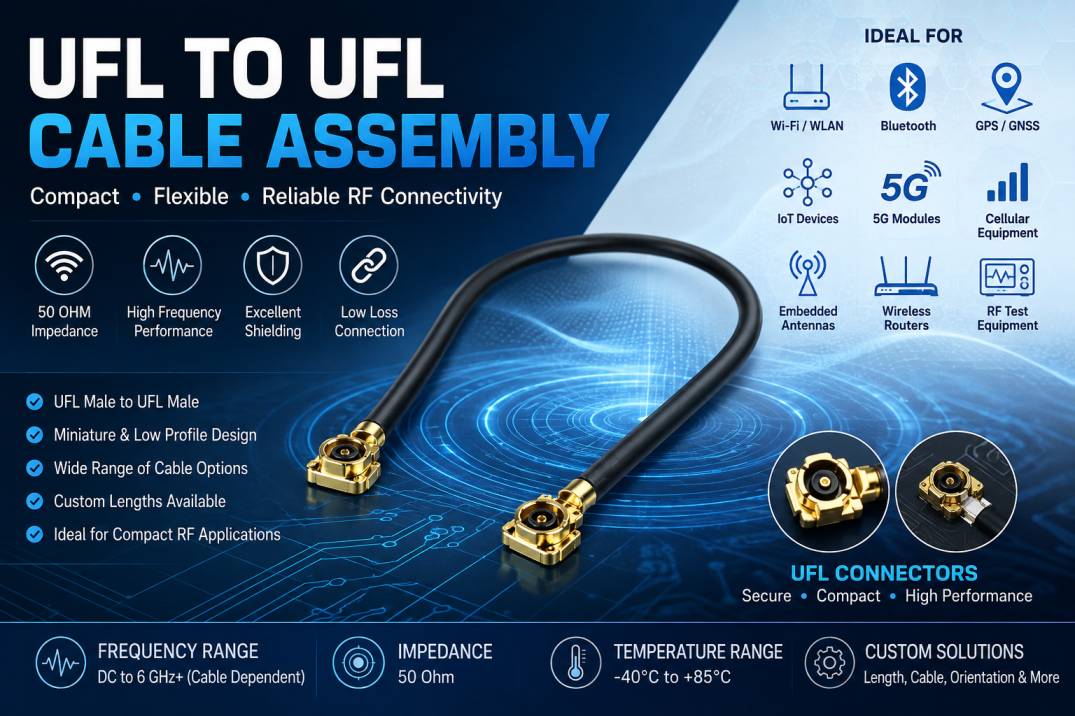
UFL to UFL Cable Assembly is a compact RF cable solution designed to connect two U.FL or IPEX-compatible miniature coaxial interfaces. These cable assemblies are widely used where space is limited and reliable high-frequency signal transmission is required. With their small form factor, low profile, flexible construction, and excellent electrical performance, UFL to UFL cable assemblies are commonly found in wireless communication equipment, IoT devices, GPS systems, WLAN modules, Bluetooth devices, cellular equipment, embedded antennas, RF test systems, and compact electronic assemblies.
A UFL connector, also commonly associated with IPEX-style miniature RF connectors, is designed for PCB-level RF interconnection. When two UFL connectors are terminated on opposite ends of a coaxial cable, the resulting UFL to UFL cable assembly provides a convenient RF connection between two miniature ports.
SRFS Teleinfra offers RF cable assemblies engineered for demanding applications where size, signal integrity, mechanical reliability, and repeatable RF performance are important. UFL to UFL cable assemblies can be customized according to cable type, length, connector orientation, impedance, operating frequency, and application requirements.
What Is a UFL to UFL Cable Assembly?
A UFL to UFL Cable Assembly is a miniature coaxial cable terminated with UFL-type connectors at both ends. The assembly provides a controlled-impedance RF path between two compatible miniature RF interfaces.
Unlike conventional RF cables using larger connectors such as SMA, N-Type, or TNC, UFL assemblies are optimized for applications where PCB space and component height are restricted. The connector has a very small footprint and is typically mounted onto a PCB through a mating receptacle.
The cable assembly generally consists of a miniature coaxial cable, center conductor, dielectric material, shielding layer, outer jacket, and two UFL connectors. Depending on the design, the cable can be selected for flexibility, low loss, phase stability, temperature resistance, or mechanical durability.
UFL to UFL Cable Assembly Construction
The construction of a UFL to UFL cable assembly is critical to achieving reliable RF performance. Each component contributes to signal integrity and mechanical reliability.
Center Conductor
The center conductor carries the RF signal through the cable. It is commonly manufactured using copper or copper-alloy materials and may have plating selected to improve conductivity, corrosion resistance, and solderability.
A high-quality center conductor helps reduce conductor losses and maintains consistent electrical performance across the specified frequency range.
Dielectric
The dielectric material separates the center conductor from the shielding system and determines an important part of the cable’s electrical characteristics.
Low-loss dielectric materials can be selected for high-frequency applications to minimize attenuation and maintain signal quality.
Shielding
The shielding layer protects the RF signal from electromagnetic interference and reduces unwanted signal radiation.
Depending on the cable construction, shielding can consist of a metallic foil, braided shield, or multilayer shielding system. Higher shielding effectiveness can be particularly important in dense wireless and electronic environments.
Outer Jacket
The outer jacket provides mechanical protection against abrasion, bending, environmental exposure, and handling.
Different jacket materials can be selected depending on temperature range, flexibility requirements, chemical exposure, and installation conditions.
UFL Connectors
UFL connectors provide the miniature interface between the coaxial cable and the PCB-mounted RF port.
Because of their small size, UFL connectors are suitable for compact electronic designs. Proper connector construction and termination are essential for maintaining low insertion loss, controlled impedance, and reliable mating performance.
Key Features of UFL to UFL Cable Assembly
UFL to UFL cable assemblies provide several advantages for modern RF and wireless electronic systems.
Compact Miniature Design
The most important advantage is the extremely compact connector footprint. UFL assemblies can be routed through small PCB areas where conventional RF connectors may not fit.
Low Profile
The low-profile design makes UFL cable assemblies suitable for thin electronic devices, embedded wireless modules, compact communication equipment, and space-constrained enclosures.
Controlled Impedance
RF cable assemblies are designed around a controlled impedance, commonly 50 Ohms, to minimize reflections and maintain signal integrity.
Flexible Cable Construction
Miniature coaxial cables can provide sufficient flexibility for routing around PCB components and within compact housings.
High-Frequency Performance
Depending on the selected cable and connector configuration, UFL to UFL assemblies can support high-frequency RF applications while maintaining controlled electrical characteristics.
Low Insertion Loss
Properly selected cable and connector components help reduce insertion loss, allowing efficient RF signal transmission between connected modules.
Reliable RF Connection
A precision-manufactured connector and properly terminated cable provide consistent electrical and mechanical performance.
Custom Lengths
Cable assemblies can be manufactured in different lengths according to equipment and PCB layout requirements.
Custom Connector Orientation
Connector orientation can be customized to simplify routing and installation in compact systems.
UFL to UFL Cable Assembly Specifications
Typical specifications can include:
Product Type: UFL to UFL RF Cable Assembly
Connector Type: UFL / IPEX Compatible
Connector Configuration: UFL Male to UFL Male
Impedance: 50 Ohms
Cable Type: Miniature Coaxial Cable
Cable Length: Customizable
Operating Frequency: Application dependent
Insertion Loss: Cable and frequency dependent
VSWR: Application dependent
Shielding: Single or multilayer shielding depending on cable selection
Jacket Material: Application dependent
Operating Temperature: Dependent on selected cable and connector materials
RoHS Compliance: Available according to material and manufacturing requirements
Application: Wireless, RF, GPS, IoT, WLAN, cellular, Bluetooth, embedded antenna and test applications
The exact electrical and mechanical specifications should be finalized according to the equipment design and required operating frequency.
UFL vs IPEX: Are They the Same?
UFL and IPEX are often used interchangeably in the RF industry, but they can refer to different connector families, manufacturers, or naming conventions.
U.FL is strongly associated with Hirose’s miniature RF connector family, while IPEX is commonly used as a broader industry term for miniature RF connectors and compatible interfaces. Different generations and series can have differences in mating height, dimensions, electrical characteristics, and mechanical compatibility.
Therefore, it is important to confirm the exact connector series and mating interface before selecting a UFL to UFL cable assembly.
Why 50 Ohm Impedance Is Important
Most RF communication systems use a 50 Ohm impedance environment. Maintaining the same impedance throughout the signal path reduces impedance discontinuities and minimizes signal reflections.
If the cable, connector, PCB transmission line, or RF device has a significantly different impedance, part of the transmitted energy may be reflected toward the source.
This can result in increased VSWR, insertion loss, reduced power transfer, and degraded system performance.
A properly designed UFL to UFL cable assembly maintains controlled impedance across the cable and connector interface to support efficient RF signal transmission.
UFL to UFL Cable Assembly Electrical Performance
Electrical performance depends on the complete cable assembly rather than the connector alone.
Important parameters include insertion loss, return loss, VSWR, impedance, shielding effectiveness, phase stability, power handling capability, and operating frequency.
Insertion Loss
Insertion loss represents the amount of RF power lost as the signal travels through the cable assembly. Shorter cables generally provide lower cable loss, while longer assemblies introduce greater attenuation.
Return Loss
Return loss indicates how effectively the RF connection prevents signal reflections. Higher return loss generally indicates better impedance matching.
VSWR
Voltage Standing Wave Ratio describes the degree of impedance mismatch within the RF signal path. Lower VSWR generally indicates better matching.
Shielding Effectiveness
Shielding effectiveness describes the cable’s ability to prevent electromagnetic interference from entering or leaving the cable.
Phase Stability
For applications where phase accuracy is important, cable construction and mechanical movement can influence phase performance. Specialized cable constructions can be selected for phase-sensitive applications.
UFL to UFL Cable Assembly Applications
UFL to UFL cable assemblies are used across a wide range of RF and wireless applications.
Wi-Fi and WLAN Equipment
Wireless modules often require compact connections between RF transceivers and antennas. UFL assemblies provide a convenient connection between miniature PCB-mounted RF interfaces.
Bluetooth Devices
Bluetooth-enabled products frequently use compact antenna systems. UFL cable assemblies can connect the wireless module to an external or internal antenna.
GPS and GNSS Equipment
GPS and GNSS receivers require reliable RF connections between receiver modules and antennas. Miniature coaxial assemblies are useful where PCB and enclosure space is limited.
Cellular Communication Equipment
Cellular modules may use miniature RF interfaces for connecting antennas and RF subassemblies. UFL assemblies can provide flexible routing within compact equipment.
IoT Devices
IoT products often prioritize small dimensions and low power consumption. UFL cable assemblies are suitable for connecting wireless modules, antennas, and RF circuits in compact IoT hardware.
Embedded Antenna Systems
Embedded antennas frequently require miniature coaxial connections. UFL to UFL assemblies can connect the antenna section with a wireless communication module.
Wireless Routers
Compact wireless networking equipment can use miniature RF cable assemblies to connect PCB radio modules with antennas.
RF Test Equipment
UFL cable assemblies may also be used in laboratory and engineering environments for connecting miniature RF modules and test interfaces.
Medical Electronics
Compact medical electronic devices can require miniature RF connections where equipment size and reliable signal transmission are important.
Industrial Wireless Systems
Industrial wireless sensors and communication modules can use miniature coaxial assemblies for RF signal routing.
Advantages of UFL to UFL Cable Assembly
Saves PCB Space
The miniature connector footprint allows designers to use valuable PCB real estate efficiently.
Supports Compact Product Design
UFL assemblies are particularly useful for lightweight and thin electronic products.
Easy RF Module Interconnection
The cable provides a flexible connection between two compatible miniature RF interfaces.
Reduced Cable Routing Constraints
The flexible coaxial cable can be routed around components and through compact enclosures.
Customizable
Cable length, connector orientation, cable construction, and other parameters can be selected according to the application.
Suitable for High-Density Electronics
UFL connectors are appropriate for modern electronics where multiple RF components must fit into a limited area.
UFL to UFL Cable Assembly Manufacturing Process
Manufacturing begins with selecting the appropriate miniature coaxial cable and connector components.
The cable is cut to the specified length with controlled dimensional tolerances. The cable ends are then prepared according to the connector termination design.
The UFL connectors are precisely attached to the cable using controlled manufacturing processes. Proper termination is essential because incorrect stripping, excessive mechanical stress, or poor connector attachment can negatively affect RF performance.
After assembly, the cable may undergo electrical and mechanical inspection. Depending on customer requirements, testing can include continuity, impedance-related measurements, VSWR, return loss, insertion loss, dimensional inspection, connector retention, and visual quality inspection.
Factors to Consider When Selecting a UFL to UFL Cable Assembly
Selecting the correct cable assembly requires more than simply matching the connector type.
Operating Frequency
The cable and connector should be suitable for the complete operating frequency range of the application.
Cable Length
Longer cables generally introduce greater attenuation. The shortest practical cable length is often preferred when minimizing RF loss is important.
Connector Compatibility
The exact UFL or IPEX interface must be verified for mechanical and electrical compatibility.
Cable Diameter
Smaller cables save space but may have different attenuation, power handling, mechanical strength, and flexibility characteristics.
Bending Requirements
If the cable must be routed through tight spaces, a flexible miniature coaxial cable should be selected.
Temperature
The cable and connector materials must be suitable for the expected operating temperature range.
Environmental Conditions
Applications exposed to vibration, humidity, chemicals, or repeated movement may require specialized cable and connector constructions.
Electrical Requirements
Important parameters include impedance, VSWR, insertion loss, return loss, shielding effectiveness, and power handling.
UFL to UFL Cable Assembly for 5G and Wireless Applications
Modern 5G and wireless devices require compact RF interconnect solutions capable of supporting high-frequency signal transmission.
UFL cable assemblies can be useful inside compact wireless modules and communication equipment where space is limited. They can provide flexible connections between RF circuits, antennas, modules, and embedded wireless subsystems.
As wireless equipment becomes smaller and more densely integrated, miniature coaxial cable assemblies continue to play an important role in RF interconnection design.
UFL to UFL Cable Assembly Quality Considerations
Quality is especially important for miniature RF cable assemblies because small dimensional variations can affect electrical performance.
Important quality considerations include precise cable stripping, consistent connector attachment, controlled cable length, proper shielding termination, connector dimensional accuracy, and reliable mechanical retention.
A professional RF cable assembly manufacturer should maintain appropriate process controls and perform inspection according to customer specifications.
Custom UFL to UFL Cable Assembly
Custom UFL to UFL cable assemblies can be manufactured according to specific equipment requirements.
Customization may include:
Cable length
Cable diameter
Cable type
Connector series
Connector orientation
Connector angle
Mating height
Operating frequency
Impedance
Jacket material
Temperature rating
Shielding construction
Labeling and packaging
Custom assemblies are particularly useful for OEMs, telecom equipment manufacturers, wireless product developers, RF laboratories, IoT manufacturers, and system integrators.
UFL to UFL Cable Assembly from SRFS Teleinfra
SRFS Teleinfra provides RF cable assemblies and interconnect solutions for telecommunications, wireless communication, RF testing, industrial electronics, and other high-frequency applications.
UFL to UFL cable assemblies can be supplied according to application-specific requirements, including cable length, connector configuration, RF performance, and mechanical dimensions.
The focus is on reliable RF interconnection, controlled impedance, repeatable manufacturing, and application-specific customization.
For OEM and project requirements, customers can specify the required connector interface, cable length, frequency range, impedance, routing configuration, and environmental conditions.
How to Order a UFL to UFL Cable Assembly
When requesting a quotation for a UFL to UFL cable assembly, provide the following information:
- Connector type and exact series
- Connector configuration
- Required cable length
- Required impedance
- Operating frequency
- Cable diameter preference
- Connector orientation
- Operating temperature
- Required VSWR or return loss
- Required insertion loss
- Quantity
- Any special environmental or mechanical requirements
Providing these details helps the manufacturer select the correct cable and connector combination.
Conclusion
UFL to UFL Cable Assembly is an important miniature RF interconnect solution for modern wireless and electronic systems. Its compact size, low-profile construction, flexible routing capability, and controlled RF performance make it suitable for applications including Wi-Fi, Bluetooth, GPS, GNSS, cellular communication, IoT, embedded antennas, wireless modules, industrial electronics, and RF testing.
The correct assembly should be selected based on connector compatibility, frequency range, impedance, cable length, insertion loss, VSWR, shielding, temperature, flexibility, and mechanical requirements.
For applications requiring reliable miniature RF interconnections, a properly engineered UFL to UFL cable assembly can provide an efficient connection while helping manufacturers maintain compact product dimensions and dependable wireless performance.
Frequently Asked Questions About UFL to UFL Cable Assembly
What is a UFL to UFL cable assembly?
A UFL to UFL cable assembly is a miniature coaxial RF cable terminated with UFL-type connectors at both ends. It is used to connect compatible miniature RF interfaces in compact electronic and wireless equipment.
What is the impedance of a UFL to UFL cable assembly?
UFL to UFL RF cable assemblies are commonly designed with a 50 Ohm impedance for use in RF and wireless communication systems.
What is a UFL connector used for?
A UFL connector is used to provide a compact RF connection between a PCB-mounted miniature RF interface and a coaxial cable or RF module.
Are UFL and IPEX connectors the same?
UFL and IPEX are often used as industry terms for miniature RF connector interfaces, but exact dimensions and mating specifications can differ. The specific connector series should always be verified before ordering.
Can UFL to UFL cable assemblies be customized?
Yes. UFL to UFL assemblies can typically be customized for cable length, cable type, connector configuration, connector orientation, electrical requirements, and environmental conditions.
What frequency can a UFL to UFL cable assembly support?
The supported frequency depends on the exact connector series and coaxial cable construction. The required frequency range should be specified when selecting the assembly.
Where are UFL to UFL cable assemblies used?
They are used in Wi-Fi, Bluetooth, GPS, GNSS, cellular modules, IoT devices, wireless routers, embedded antenna systems, industrial electronics, medical electronics, and RF test equipment.
Does cable length affect UFL cable performance?
Yes. Increasing cable length generally increases attenuation and can affect overall RF performance. A suitable cable length should therefore be selected based on the system requirements.
Can UFL to UFL cables be used for 5G applications?
They can be used in suitable 5G and high-frequency wireless equipment when the selected cable and connector combination meets the required frequency, insertion loss, VSWR, and mechanical specifications.
How do I select the right UFL to UFL cable assembly?
Select the assembly according to the exact connector interface, impedance, operating frequency, cable length, cable diameter, flexibility, insertion loss, VSWR, temperature range, and mechanical routing requirements.