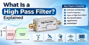
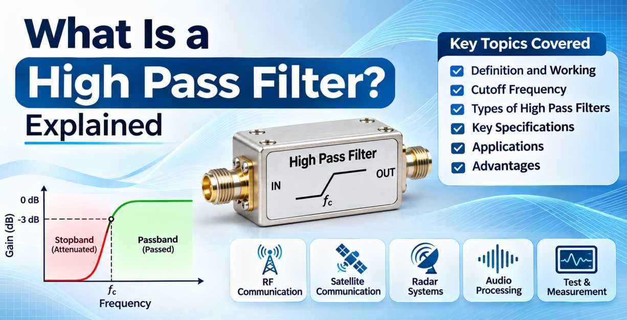
A high pass filter is an essential electronic component used in RF, microwave, wireless communication, audio processing, and signal transmission systems. Its primary function is to allow signals with frequencies higher than a specified cutoff frequency to pass through while attenuating signals with frequencies below that limit.
High pass filters play an important role in maintaining signal quality, reducing unwanted low-frequency interference, and improving the performance of electronic and communication systems. They are widely used in radio frequency circuits, antenna systems, wireless networks, test and measurement equipment, and various electronic applications.
In modern communication technology, where accurate signal transmission and frequency management are critical, high pass filters help isolate the required frequency bands and minimize unwanted signals.
This guide explains what a high pass filter is, how it works, its different types, important specifications, advantages, and applications in RF and microwave engineering.
1. What Is a High Pass Filter?
A high pass filter (HPF) is an electronic filter designed to pass signals above a particular frequency, known as the cutoff frequency, while reducing the amplitude of signals below that frequency.
In simple terms, a high pass filter allows high-frequency signals to pass through and blocks or attenuates low-frequency signals.
Every high pass filter has a defined frequency response that determines how effectively it separates the desired high-frequency signals from unwanted low-frequency components.
For example, if a high pass filter has a cutoff frequency of 1 GHz, it is designed to attenuate frequencies below 1 GHz and allow frequencies above 1 GHz to pass through its passband. However, the actual attenuation and insertion loss depend on the filter design and its specified characteristics.
High pass filters are commonly used in RF and microwave systems to remove unwanted low-frequency signals, isolate operating frequency bands, and improve the overall performance of communication equipment.
2. How Does a High Pass Filter Work?
A high pass filter works by using frequency-dependent electrical characteristics to control which signals can pass through a circuit.
Its operation depends on the filter design, which may use capacitors, inductors, resistors, or specially designed microwave structures.
In a basic passive high pass filter circuit, a capacitor is connected in series with the input signal, while a resistor is connected between the output and ground.
The capacitor blocks steady-state DC signals and offers lower reactance as the signal frequency increases. As a result, high-frequency signals can pass more easily, while low-frequency signals experience greater attenuation.
The basic operation can be explained in three stages:
Low-Frequency Signals: Signals below the cutoff frequency experience higher attenuation. The filter reduces their amplitude before they reach the output.
Cutoff Frequency: This is the transition point between the stopband and passband. For a typical first-order filter, the output amplitude is approximately 70.7% of the input amplitude at the cutoff frequency, corresponding to -3 dB.
High-Frequency Signals: Signals above the cutoff frequency pass through the filter with relatively low attenuation, depending on its insertion loss and passband characteristics.
The effectiveness of a high pass filter depends on its frequency range, filter order, insertion loss, rejection level, and impedance matching.
3. What Is the Cutoff Frequency of a High Pass Filter?
The cutoff frequency is one of the most important parameters of a high pass filter. It defines the frequency at which the filter transitions from its stopband to its passband.
For a basic RC high pass filter, the cutoff frequency is calculated using the following formula:
\[ f_c=\frac{1}{2\pi RC} \]
Where:
- \(f_c\) = Cutoff frequency in Hertz (Hz)
- \(R\) = Resistance in Ohms (Ω)
- \(C\) = Capacitance in Farads (F)
- \(\pi\) = Mathematical constant approximately equal to 3.1416
For example, if a high pass filter has a resistance of 1 kΩ and a capacitance of 0.1 µF, its cutoff frequency is approximately 1.59 kHz.
In RF and microwave applications, cutoff frequency is generally determined by the electrical design, component values, transmission-line structures, and electromagnetic properties of the filter.
It is important to understand that the cutoff frequency does not represent an absolute boundary where all lower frequencies are blocked. Instead, it marks a defined point in the filter’s frequency response.
4. Types of High Pass Filters
High pass filters are available in different configurations depending on their operating frequency, performance requirements, circuit complexity, and application.
4.1 Passive High Pass Filter
A passive high pass filter uses passive electronic components such as resistors, capacitors, and inductors.
It does not require an external power supply to perform its filtering function. Passive filters are widely used in electronic circuits, RF systems, and signal-processing applications.
Advantages include simple construction, reliable operation, and no requirement for an active amplification stage.
4.2 Active High Pass Filter
An active high pass filter uses active electronic components, such as operational amplifiers, along with resistors and capacitors.
Unlike passive filters, active high pass filters can provide signal amplification in addition to frequency filtering.
They are commonly used in audio systems, instrumentation, and signal-conditioning circuits where gain and frequency control are required.
4.3 RC High Pass Filter
An RC high pass filter consists of a resistor and a capacitor. It is one of the simplest high pass filter configurations.
The capacitor allows higher-frequency signals to pass while reducing lower-frequency components.
RC high pass filters are commonly used in audio circuits, signal coupling, and basic electronic applications.
4.4 LC High Pass Filter
An LC high pass filter uses inductors and capacitors to achieve frequency selection.
These filters are useful in RF and high-frequency applications because they can provide improved frequency selectivity compared with simple first-order RC designs.
Their performance depends on component values, circuit topology, quality factor, and operating frequency.
4.5 Microwave High Pass Filter
A microwave high pass filter is designed to operate at high frequencies, typically within microwave frequency bands.
These filters may use microstrip, stripline, waveguide, coaxial, or other microwave structures.
They are designed to provide controlled passband performance, low insertion loss, high stopband rejection, and suitable impedance matching.
Microwave high pass filters are used in wireless communication equipment, radar systems, satellite communication, and RF test setups.
4.6 Lumped Element High Pass Filter
A lumped element high pass filter uses discrete capacitors and inductors to achieve the required frequency response.
It is commonly used when the operating frequency allows practical implementation of lumped components.
4.7 Distributed Element High Pass Filter
A distributed element high pass filter uses transmission-line structures instead of relying entirely on discrete components.
These designs are particularly useful at microwave frequencies, where physical dimensions and electromagnetic behavior become important.
They are commonly implemented using microstrip, stripline, and waveguide technologies.
5. Important Specifications of a High Pass Filter
When selecting a high pass filter for RF, microwave, or electronic applications, it is important to understand its technical specifications. These parameters determine how effectively the filter performs within a particular frequency range.
5.1 Cutoff Frequency
Cutoff frequency is the frequency at which the filter response reaches its specified transition point, commonly defined as -3 dB for a conventional filter response.
It determines the lower frequency boundary of the passband.
5.2 Passband Frequency
The passband refers to the range of frequencies that a high pass filter allows to pass with relatively low attenuation.
For example, a filter designed with a 2 GHz cutoff frequency may have a specified passband extending from 2 GHz to a higher operating frequency, depending on its design.
5.3 Stopband Frequency
The stopband is the frequency range where the filter significantly attenuates unwanted signals.
A high-quality high pass filter should provide sufficient stopband rejection to prevent unwanted low-frequency signals from affecting the performance of the connected equipment.
5.4 Insertion Loss
Insertion loss measures the reduction in signal power caused by inserting a filter into a transmission path.
It is generally expressed in decibels (dB).
Lower insertion loss is desirable because it allows more of the intended signal to reach the output.
In RF and microwave applications, low insertion loss is particularly important because excessive signal loss can reduce system efficiency and affect receiver sensitivity.
5.5 Return Loss
Return loss indicates how much signal power is reflected back toward the source due to impedance mismatch.
It is expressed in decibels (dB).
A higher return loss generally indicates better impedance matching and lower signal reflection.
For many RF applications, filters are designed for 50-ohm impedance systems, although other impedance configurations may also be used.
5.6 Stopband Rejection
Stopband rejection describes the filter’s ability to attenuate unwanted frequencies below the cutoff frequency.
It is generally measured in decibels.
Higher stopband rejection is beneficial when strong unwanted signals must be prevented from entering sensitive RF equipment.
5.7 Operating Frequency Range
The operating frequency range specifies the frequencies over which the filter is designed to perform according to its published specifications.
Selecting a filter with an appropriate frequency range is essential for ensuring compatibility with the intended RF or microwave system.
5.8 Power Handling Capability
Power handling capability defines the maximum RF power that a high pass filter can safely handle under specified operating conditions.
This specification is especially important in high-power RF transmitters, communication infrastructure, and testing applications.
5.9 Impedance
Impedance is an important consideration in RF filter selection.
Many RF and microwave systems use 50-ohm impedance to maintain compatibility between transmitters, receivers, cables, connectors, and other components.
Proper impedance matching helps minimize signal reflections and maintain efficient signal transmission.
5.10 Filter Order
Filter order determines how quickly the filter attenuates frequencies below the cutoff frequency.
A higher-order filter generally provides a steeper transition between the stopband and passband.
For example:
- First-order filter: 6 dB per octave attenuation slope.
- Second-order filter: 12 dB per octave attenuation slope.
- Third-order filter: 18 dB per octave attenuation slope.
- Fourth-order filter: 24 dB per octave attenuation slope.
The appropriate filter order depends on the required frequency selectivity and system performance.
6. High Pass Filter Frequency Response
The frequency response of a high pass filter explains how its output signal changes according to the input frequency.
It is generally represented using a frequency response graph, where frequency is plotted on the horizontal axis and signal gain or attenuation is plotted on the vertical axis.
A typical high pass filter frequency response consists of three important regions.
Stopband Region: This region contains frequencies below the cutoff frequency. Signals in this range are attenuated.
Transition Region: This region represents the gradual change between the stopband and passband. The filter response increases as the frequency approaches the passband.
Passband Region: Frequencies above the cutoff frequency are allowed to pass with relatively low attenuation.
The shape of the frequency response depends on the filter design and its characteristics.
Different filter responses can be selected according to the application.
Common High Pass Filter Responses
Butterworth Filter: Provides a maximally flat passband response without ripple. It is suitable for applications where smooth frequency response is important.
Chebyshev Filter: Provides a sharper transition between the passband and stopband compared with a Butterworth filter of the same order, but introduces ripple in either the passband or stopband depending on the design.
Bessel Filter: Offers a relatively consistent group delay and good phase characteristics. It is useful in applications where signal waveform preservation is important.
Elliptic Filter: Provides a very sharp transition between the passband and stopband, with ripple in both regions. It is useful when high selectivity is required within a limited filter order.
7. Applications of High Pass Filters
High pass filters are widely used across different industries because they help control frequency ranges and reduce unwanted low-frequency signals.
Some of the major applications include:
7.1 RF Communication Systems
RF communication systems use high pass filters to separate desired frequency bands from unwanted low-frequency components.
They help maintain signal quality in transmitters, receivers, RF modules, and wireless communication equipment.
High pass filters are also used in RF front-end circuits to improve frequency selection and reduce interference.
7.2 Microwave Communication
Microwave communication systems operate at high frequencies and require precise frequency management.
Microwave high pass filters help control the frequency range of signals and reduce unwanted components.
They are used in microwave transmitters, receivers, communication links, and microwave test equipment.
7.3 Antenna Systems
Antenna systems are designed to operate within specific frequency ranges.
High pass filters can be used with antenna systems to attenuate unwanted lower-frequency signals before they reach sensitive receiver circuits.
They are particularly useful in applications involving multiple frequency bands and complex RF environments.
7.4 Wireless Communication Networks
Modern wireless communication networks require accurate frequency management to support reliable signal transmission.
High pass filters can help reduce unwanted low-frequency interference and support frequency-band separation in wireless equipment.
They are relevant to cellular infrastructure, 4G LTE systems, 5G networks, and other wireless communication applications.
7.5 Satellite Communication
Satellite communication systems operate across specific RF and microwave frequency bands.
High pass filters help manage unwanted frequency components and support signal conditioning in satellite communication equipment.
They can be used in satellite receivers, RF front-end circuits, and microwave communication subsystems.
7.6 Radar Systems
Radar systems depend on accurate signal generation, transmission, reception, and processing.
High pass filters can help remove unwanted low-frequency components and improve signal conditioning in radar equipment.
They are used in various radar applications, including defence, aerospace, navigation, and weather monitoring.
7.7 Audio Processing Systems
In audio applications, high pass filters are used to remove unwanted low-frequency noise, rumble, and vibration.
For example, microphone circuits may use high pass filters to reduce handling noise and unwanted low-frequency interference.
They are also used in speakers, audio amplifiers, and sound-processing equipment.
7.8 Test and Measurement Equipment
Electronic testing and measurement systems require accurate signal analysis.
High pass filters are used in spectrum analyzers, oscilloscopes, RF test setups, and other measurement equipment to remove unwanted low-frequency components.
They help improve measurement accuracy and isolate the signals of interest.
7.9 Industrial Electronics
Industrial electronic equipment may experience unwanted low-frequency noise and electrical interference.
High pass filters can be used in signal-conditioning circuits to improve the quality of measurement and control signals.
7.10 Defence and Aerospace Communication
Defence and aerospace systems require reliable RF performance under demanding operating conditions.
High pass filters support frequency management in communication equipment, radar systems, navigation devices, and specialized electronic systems.
8. Difference Between High Pass Filter and Low Pass Filter
High pass filters and low pass filters are two fundamental types of electronic filters. Both control the frequency components of an electrical signal, but their operating functions are opposite.
| Parameter | High Pass Filter | Low Pass Filter |
|---|---|---|
| Main function | Passes higher frequencies | Passes lower frequencies |
| Attenuation | Reduces lower frequencies | Reduces higher frequencies |
| Cutoff frequency | Defines the lower passband boundary | Defines the upper passband boundary |
| Applications | RF circuits, audio, microwave systems | Audio circuits, power supplies, signal processing |
| Signal behavior | Blocks or attenuates low-frequency components | Blocks or attenuates high-frequency components |
| Common components | Capacitors and inductors | Capacitors and inductors |
The choice between a high pass filter and a low pass filter depends on the frequency range that needs to be retained.
A high pass filter is appropriate when higher-frequency signals are required, while a low pass filter is suitable when lower-frequency signals need to pass.
9. Difference Between High Pass Filter and Band Pass Filter
A high pass filter and a band pass filter both perform frequency selection, but they have different operating characteristics.
A high pass filter allows frequencies above a specified cutoff frequency to pass.
A band pass filter allows only a particular range of frequencies to pass while attenuating frequencies both below and above that range.
| Parameter | High Pass Filter | Band Pass Filter |
|---|---|---|
| Frequency selection | Frequencies above cutoff | Frequencies within a defined band |
| Lower frequency limit | Defined | Defined |
| Upper frequency limit | Depends on filter design | Defined |
| Passband | Extends above cutoff | Limited frequency range |
| Main application | Removing low-frequency signals | Selecting a specific frequency band |
For example, a high pass filter may allow signals above 1 GHz to pass, whereas a band pass filter may allow only signals between 1 GHz and 2 GHz to pass.
10. Advantages of Using a High Pass Filter
High pass filters offer several advantages in electronic and communication systems.
1. Reduces Low-Frequency Interference: High pass filters attenuate unwanted low-frequency signals that may affect system performance.
2. Improves Signal Quality: By removing unwanted frequency components, they help maintain cleaner signals.
3. Supports RF Frequency Selection: They help isolate the required frequency range in RF and microwave circuits.
4. Enhances System Performance: Proper filtering can improve the performance of receivers, transmitters, and other electronic equipment.
5. Multiple Design Options: High pass filters are available in passive, active, lumped-element, and distributed-element configurations.
6. Suitable for Different Industries: They are used in telecommunications, aerospace, defence, audio engineering, industrial electronics, and testing applications.
7. Helps Protect Sensitive Circuits: Appropriate filtering can reduce unwanted signals entering sensitive electronic stages, provided the filter is correctly selected and installed.
11. How to Choose the Right High Pass Filter?
Selecting the right high pass filter requires understanding the operating requirements of the application.
The following factors should be considered before choosing an RF or microwave high pass filter.
11.1 Determine the Required Cutoff Frequency
Identify the lowest frequency that needs to pass through the filter.
Choose a cutoff frequency according to the operating frequency requirements of your system.
11.2 Check the Passband Range
Ensure that the filter supports the complete frequency range required by your application.
A suitable passband helps maintain consistent signal performance.
11.3 Evaluate Insertion Loss
Select a filter with sufficiently low insertion loss to minimize unwanted signal attenuation.
This is particularly important in sensitive RF receiver applications.
11.4 Check Stopband Rejection
Consider how much attenuation is required for unwanted lower-frequency signals.
Applications with strong interference may require higher stopband rejection.
11.5 Verify Impedance Compatibility
Check whether the filter is compatible with the impedance of the connected RF components.
A 50-ohm high pass filter is commonly used in RF and microwave communication systems.
11.6 Consider Power Handling
Check the maximum input power rating to ensure that the filter can operate safely within the required power conditions.
11.7 Check Connector Compatibility
For coaxial RF high pass filters, connector compatibility is essential.
Common connector interfaces include SMA, N-Type, BNC, and other RF connector types.
The selected connector should match the connected cables and equipment.
11.8 Consider Operating Environment
Depending on the application, temperature range, humidity, vibration, mechanical durability, and environmental conditions may also influence filter selection.
12. High Pass Filters in RF and Microwave Engineering
High pass filters are particularly important in RF and microwave engineering because modern communication systems operate across multiple frequency bands.
In these systems, unwanted signals, harmonics, and interference can affect receiver sensitivity, signal quality, and overall equipment performance.
An RF high pass filter helps attenuate frequencies below its specified cutoff point while allowing the required higher-frequency signals to pass.
For microwave applications, filter designs must account for transmission-line characteristics, electromagnetic coupling, parasitic effects, and impedance matching.
Some commonly used RF and microwave high pass filter technologies include:
- Coaxial high pass filters
- Waveguide high pass filters
- Microstrip high pass filters
- Stripline high pass filters
- Lumped-element high pass filters
- Distributed-element high pass filters
Each technology offers different advantages in terms of frequency range, power handling, physical dimensions, insertion loss, and manufacturing complexity.
The selection depends on the system architecture and technical requirements.
13. Common Challenges in High Pass Filter Design
Although high pass filters are widely used, their design and implementation involve several technical considerations.
Insertion Loss: Excessive insertion loss can reduce the signal level and negatively affect system performance.
Impedance Mismatch: Incorrect impedance matching can result in signal reflections and reduced power transfer.
Frequency Response: An unsuitable filter design may not provide the required transition between the passband and stopband.
Component Tolerances: Variations in component values can affect the cutoff frequency and overall filter performance.
Parasitic Effects: At higher frequencies, unwanted capacitance and inductance can influence filter behavior.
Power Limitations: Operating beyond the specified power rating may cause performance degradation or component damage.
Environmental Conditions: Temperature variations and mechanical conditions may affect filter characteristics.
Careful design, simulation, testing, and measurement are important to ensure reliable filter performance.
14. How Is a High Pass Filter Tested?
Testing is necessary to verify whether a high pass filter meets its specified electrical and RF performance requirements.
Common testing methods include:
Vector Network Analyzer (VNA): A VNA is used to measure the filter’s S-parameters, including insertion loss and return loss, across the specified frequency range.
Frequency Response Measurement: This test evaluates how the filter attenuates low-frequency signals and passes higher-frequency signals.
Stopband Rejection Testing: It verifies whether the filter provides the required attenuation below the cutoff frequency.
Power Handling Test: This checks the filter’s performance under its specified RF power conditions using appropriate test equipment and procedures.
Environmental Testing: Depending on the application, the filter may be evaluated under different temperature and environmental conditions.
These measurements help engineers confirm that the high pass filter performs according to its design specifications.
15. Difference Between First-Order and Higher-Order High Pass Filters
The order of a high pass filter determines its attenuation rate below the cutoff frequency.
A first-order filter provides a gradual transition, while higher-order filters offer a steeper transition and better frequency separation.
| Parameter | First-Order | Second-Order | Fourth-Order |
|---|---|---|---|
| Attenuation slope | 6 dB/octave | 12 dB/octave | 24 dB/octave |
| Circuit complexity | Low | Moderate | Higher |
| Frequency selectivity | Basic | Improved | High |
| Design requirements | Simple | Moderate | More complex |
| Typical use | Basic filtering | Signal conditioning | High-selectivity applications |
Higher-order filters are useful when unwanted frequencies need to be attenuated more rapidly. However, increasing the filter order can also increase design complexity, component requirements, and sensitivity to implementation effects.
16. Future Importance of High Pass Filters in Communication Technology
As wireless communication technology continues to develop, high pass filters remain important components in advanced electronic and RF systems.
The expansion of 5G networks, satellite communication, radar technology, aerospace electronics, and high-frequency testing is increasing the need for accurate frequency selection and signal management.
Modern RF and microwave filters are increasingly designed to provide:
- Wider operating frequency ranges
- Lower insertion loss
- Improved stopband rejection
- Better impedance matching
- Compact mechanical designs
- Higher power handling capabilities
- Improved thermal stability
- Reliable performance at microwave and millimeter-wave frequencies
These developments make high pass filters an important part of modern communication infrastructure and advanced electronic engineering.
17. Conclusion
A high pass filter is an important electronic component that allows higher-frequency signals to pass while attenuating lower-frequency signals below a specified cutoff frequency.
It plays a significant role in RF communication, microwave engineering, wireless networks, antenna systems, satellite communication, radar equipment, audio processing, and electronic testing applications.
Understanding its working principle, cutoff frequency, insertion loss, return loss, stopband rejection, impedance, and power handling capability helps engineers select the right filter for their requirements.
With the continuous development of wireless communication and high-frequency electronic technologies, high pass filters will continue to play an essential role in maintaining reliable signal transmission and efficient frequency management.
For RF and microwave applications, selecting a high pass filter with appropriate electrical specifications and operating characteristics is essential for achieving consistent system performance.
18. Frequently Asked Questions (FAQs) About High Pass Filters
Q1. What is a high pass filter?
A high pass filter is an electronic circuit or RF component that allows signals above a specified cutoff frequency to pass while attenuating signals below that frequency. It is commonly used in RF communication, audio processing, microwave systems, and electronic circuits.
Q2. What is the main purpose of a high pass filter?
The main purpose of a high pass filter is to remove or reduce unwanted low-frequency signals while allowing higher-frequency signals to pass. It helps improve signal quality and frequency separation.
Q3. What is the cutoff frequency of a high pass filter?
The cutoff frequency is the frequency at which the filter response reaches its defined transition point. For a conventional first-order high pass filter, this point corresponds to approximately -3 dB relative to the passband gain.
Q4. What are the different types of high pass filters?
Common types include passive high pass filters, active high pass filters, RC filters, LC filters, lumped-element filters, distributed-element filters, and microwave high pass filters.
Q5. What is the difference between a high pass filter and a low pass filter?
A high pass filter allows higher-frequency signals to pass and attenuates lower frequencies. A low pass filter allows lower-frequency signals to pass and attenuates higher frequencies.
Q6. Where are high pass filters used?
High pass filters are used in RF communication systems, microwave equipment, antenna systems, satellite communication, radar technology, audio equipment, wireless networks, and electronic testing instruments.
Q7. What is the formula for a high pass filter?
The cutoff frequency formula for a basic RC high pass filter is:
\[ f_c=\frac{1}{2\pi RC} \]
Here, R represents resistance and C represents capacitance.
Q8. What is the difference between an active and passive high pass filter?
A passive high pass filter uses resistors, capacitors, and inductors without requiring an external power supply for filtering. An active high pass filter uses active components, such as operational amplifiers, and can provide signal amplification.
Q9. Why are high pass filters important in RF applications?
High pass filters help attenuate unwanted low-frequency signals, support frequency selection, and improve signal management in RF and microwave systems. They are useful in communication equipment, antenna systems, and RF test setups.
Q10. What parameters should be considered when selecting an RF high pass filter?
Important parameters include cutoff frequency, passband frequency, insertion loss, return loss, stopband rejection, impedance, power handling capability, connector type, and operating temperature.