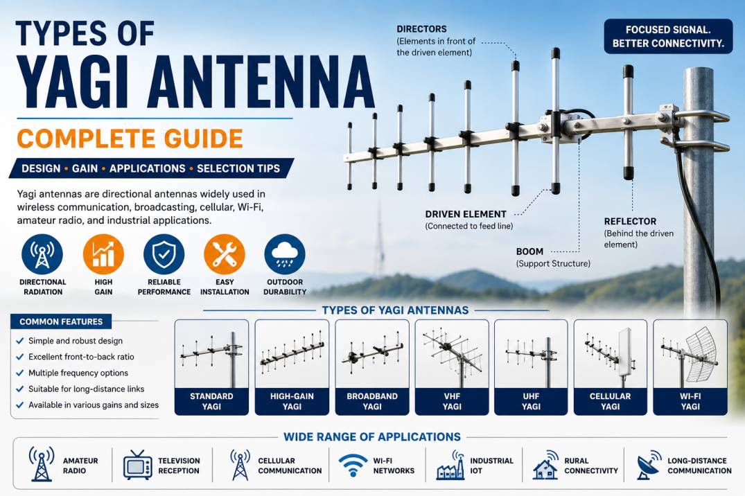
A Yagi antenna, also known as a Yagi-Uda antenna, is one of the most widely recognized directional antenna designs used in RF, wireless communication, television broadcasting, cellular systems, amateur radio, and industrial applications. Its relatively simple construction, directional radiation pattern, useful gain, and ability to concentrate RF energy make it suitable for applications where signals need to be transmitted or received primarily in one direction.
Yagi antennas are particularly useful when the location or general direction of a communication source is known. Unlike an omnidirectional antenna, which distributes RF energy over a broad horizontal area, a Yagi antenna focuses its radiation pattern along a preferred direction.
Different Yagi antenna designs are available depending on operating frequency, number of elements, gain requirement, bandwidth, polarization, physical size, and application. Common variations include standard Yagi antennas, high-gain Yagi antennas, broadband Yagi antennas, log-periodic-inspired Yagi designs, folded-dipole Yagi antennas, dual-polarized Yagi antennas, VHF Yagi antennas, UHF Yagi antennas, cellular Yagi antennas, Wi-Fi Yagi antennas, and multi-band Yagi antennas.
This guide explains the major types of Yagi antennas, their construction, working principle, specifications, applications, advantages, limitations, and selection criteria.
What Is a Yagi Antenna?
A Yagi antenna is a directional antenna consisting of multiple conductive elements arranged along a supporting boom.
A conventional Yagi antenna normally contains three primary types of elements:
- Reflector
- Driven element
- Director elements
The driven element is connected to the RF feed line and is responsible for coupling energy into or out of the antenna.
The reflector is generally positioned behind the driven element and helps direct RF energy toward the front of the antenna.
The directors are positioned in front of the driven element and help concentrate the radiation pattern in the forward direction.
The number, length, spacing, and arrangement of these elements determine important characteristics such as gain, beamwidth, front-to-back ratio, impedance, and operating frequency.
How Does a Yagi Antenna Work?
A Yagi antenna works through electromagnetic coupling between its elements.
Only the driven element is normally connected directly to the feed system. The reflector and directors are parasitic elements, meaning they are not normally connected directly to the transmission line.
When RF energy is applied to the driven element, electromagnetic fields are induced in the nearby parasitic elements. The dimensions and spacing of these elements are engineered so that their combined radiation reinforces RF energy in the desired direction and suppresses it in other directions.
During reception, the same principle works in reverse. Electromagnetic waves arriving from the preferred direction induce currents in the antenna elements, which combine to produce a useful signal at the driven element.
Main Parts of a Yagi Antenna
1. Boom
The boom is the mechanical support structure that holds the antenna elements in position.
It is commonly manufactured from aluminum or another conductive or mechanically suitable material.
2. Reflector
The reflector is normally the longest element in a conventional Yagi design.
It is positioned behind the driven element and contributes to the antenna’s directional behavior and front-to-back performance.
3. Driven Element
The driven element is the active element connected to the RF transmission line.
Depending on the design, it may be a straight dipole, folded dipole, or another driven structure.
4. Directors
Directors are generally placed in front of the driven element.
A Yagi can contain one director or many directors. Increasing the number of directors can increase directivity and gain, although the relationship is not simply proportional.
5. Feed Point
The feed point is where the RF transmission line connects to the driven element.
Depending on the application, the feed system may use connectors such as SMA, N-Type, TNC, or other RF interfaces.
Major Types of Yagi Antennas
Yagi antennas can be classified according to their frequency range, element arrangement, gain, bandwidth, polarization, physical construction, and application.
The major types include:
- Standard Yagi Antenna
- Short Yagi Antenna
- High-Gain Yagi Antenna
- Broadband Yagi Antenna
- VHF Yagi Antenna
- UHF Yagi Antenna
- HF Yagi Antenna
- Cellular Yagi Antenna
- 3G-4G Yagi Antenna
- 5G Sub-6 GHz Yagi Antenna
- Wi-Fi Yagi Antenna
- Dual-Band Yagi Antenna
- Multi-Band Yagi Antenna
- Folded-Dipole Yagi Antenna
- Dual-Polarized Yagi Antenna
- Cross-Polarized Yagi Antenna
- Portable Yagi Antenna
- Rotatable Yagi Antenna
- Arrayed Yagi Antenna
- Custom Yagi Antenna
1. Standard Yagi Antenna
A standard Yagi antenna uses a conventional arrangement of one reflector, one driven element, and one or more directors.
It is designed for a relatively specific frequency range and provides directional gain compared with a simple dipole antenna.
Features
- Simple construction
- Directional radiation
- Moderate gain
- Relatively low weight
- Easy installation
- Straightforward maintenance
Applications
Standard Yagi antennas are used in:
- Amateur radio
- Television reception
- RF experiments
- Wireless communication
- Signal monitoring
- Industrial communication
2. Short Yagi Antenna
A short Yagi uses a relatively small number of elements.
It provides a more compact physical structure compared with long, high-gain Yagi antennas.
Advantages
- Compact dimensions
- Lower weight
- Easier installation
- Lower mechanical loading
- Suitable for portable applications
Applications
- Amateur radio
- Portable RF equipment
- Short-range directional communication
- Field testing
- Compact wireless systems
The trade-off is generally lower directivity and gain compared with a longer Yagi designed for the same frequency.
3. High-Gain Yagi Antenna
A high-gain Yagi uses an optimized element arrangement and typically more directors to produce greater forward directivity.
High-gain Yagi antennas are useful when a communication system needs a stronger directional link.
Applications
- Long-distance wireless links
- Cellular signal reception
- Amateur radio
- Remote monitoring
- Rural communication
- RF measurement
- Specialized telemetry
Important Consideration
High gain normally comes with a narrower beamwidth and potentially greater physical length. Therefore, accurate alignment becomes more important.
4. Broadband Yagi Antenna
A conventional Yagi is often optimized around a relatively limited frequency range. Broadband Yagi designs modify element geometry, spacing, or matching structures to achieve wider frequency coverage.
Advantages
- Wider operating bandwidth
- Supports multiple frequencies
- Flexible deployment
- Useful for multi-channel systems
Applications
- Broadband RF monitoring
- Multi-frequency communication
- Cellular systems
- Measurement equipment
- Wideband wireless systems
5. VHF Yagi Antenna
A VHF Yagi antenna is designed for Very High Frequency applications.
VHF generally covers frequencies from 30 MHz to 300 MHz, although the exact operating range of a particular antenna depends on its design.
Because wavelength is relatively long at VHF frequencies, VHF Yagi antennas can become physically large.
Applications
- Amateur radio
- VHF communication
- Radio monitoring
- Telemetry
- Specialized communication systems
6. UHF Yagi Antenna
A UHF Yagi antenna is designed for frequencies in the Ultra High Frequency range.
UHF wavelengths are shorter than VHF wavelengths, allowing UHF Yagi antennas to be physically smaller for a comparable electrical design.
Applications
- Television reception
- Wireless communication
- Cellular systems
- RFID-related applications
- Industrial telemetry
- RF testing
7. HF Yagi Antenna
HF Yagi antennas operate in the High Frequency range and are commonly used in amateur radio and specialized communication applications.
Because HF wavelengths are relatively long, these antennas can be physically large, particularly when designed for lower frequencies.
Applications
- Amateur radio
- Long-distance communication
- Radio experimentation
- HF monitoring
- Specialized communication systems
8. Cellular Yagi Antenna
A cellular Yagi antenna is specifically designed for cellular frequency bands.
It is generally used when a cellular signal source is located in a known direction and directional gain is beneficial.
Applications
- Cellular routers
- LTE gateways
- Rural broadband
- Industrial IoT
- Remote monitoring
- Cellular signal reception
Benefits
- Directional signal reception
- Higher gain than many small omnidirectional antennas
- Useful in weak-signal environments
- Suitable for fixed installations
9. 3G-4G Yagi Antenna
A 3G-4G Yagi antenna is designed to cover one or more frequency bands associated with third-generation and fourth-generation cellular systems.
Depending on the design, it may support bands around 700 MHz, 800 MHz, 850 MHz, 900 MHz, 1800 MHz, 2100 MHz, 2300 MHz, 2500 MHz, or 2600 MHz.
Applications
- LTE routers
- 3G-4G modems
- Rural connectivity
- Industrial communication
- Remote surveillance
- Agricultural monitoring
Antenna specifications should always be checked against the exact LTE bands used by the target network.
10. 5G Sub-6 GHz Yagi Antenna
Yagi-type directional antennas can also be designed for selected 5G Sub-6 GHz frequency ranges.
These antennas are different from millimeter-wave 5G antenna arrays and should not be treated as interchangeable.
Applications
- Fixed wireless access
- Private wireless networks
- Outdoor wireless links
- RF testing
- Specialized 5G installations
The required frequency range must be matched carefully to the target 5G band.
11. Wi-Fi Yagi Antenna
A Wi-Fi Yagi antenna is a directional antenna designed for Wi-Fi frequency ranges, commonly including 2.4 GHz and selected 5 GHz applications.
Wi-Fi Yagi antennas can be useful for directional wireless links where the communicating access point is located in a known direction.
Applications
- Point-to-point Wi-Fi
- Outdoor Wi-Fi
- Wireless bridges
- Rural connectivity
- Remote network access
Advantages
- Focused RF energy
- Increased directional gain
- Reduced coverage behind the antenna
- Suitable for long-distance line-of-sight links
12. Dual-Band Yagi Antenna
A dual-band Yagi antenna is designed to operate across two frequency bands.
The two bands may be selected according to the application, such as:
- 2.4 GHz and 5 GHz
- Two cellular bands
- Two amateur-radio bands
- Other specified RF ranges
Dual-band Yagi antennas are useful when one directional antenna needs to support two separate frequency ranges.
13. Multi-Band Yagi Antenna
A multi-band Yagi antenna supports several frequency bands within a single antenna structure.
Design approaches may include:
- Multiple driven elements
- Carefully optimized parasitic elements
- Traps
- Matching networks
- Multiband element structures
Applications
- Cellular communication
- Amateur radio
- Multi-frequency monitoring
- RF testing
- Broadband wireless systems
Multi-band designs can simplify installation but may involve trade-offs in gain, size, bandwidth, and impedance matching.
14. Folded-Dipole Yagi Antenna
A folded-dipole Yagi uses a folded dipole as its driven element.
The folded driven element can provide useful impedance and bandwidth characteristics and is commonly found in various antenna designs.
Advantages
- Practical feed arrangement
- Useful impedance characteristics
- Robust mechanical construction
- Suitable for several RF applications
15. Dual-Polarized Yagi Antenna
A dual-polarized Yagi antenna supports two polarization orientations.
The two polarizations can be used for different communication channels or MIMO-related applications, depending on the system architecture.
Advantages
- Supports polarization diversity
- Useful for modern wireless communication
- Can improve link flexibility
- Suitable for specialized MIMO systems
Applications
- Cellular communication
- Wireless broadband
- RF measurement
- Specialized directional links
16. Cross-Polarized Yagi Antenna
Cross-polarized Yagi designs use elements arranged to provide two orthogonal polarization states.
They can be useful where polarization diversity or dual-polarized operation is required.
Applications
- MIMO systems
- Wireless communication
- Cellular networks
- RF research
- Directional wireless links
17. Portable Yagi Antenna
Portable Yagi antennas are designed for easy transportation and field deployment.
They are generally smaller, lighter, or mechanically designed to be assembled and disassembled easily.
Applications
- Amateur radio
- Field testing
- RF surveys
- Signal hunting
- Emergency communication
- Outdoor experiments
18. Rotatable Yagi Antenna
A rotatable Yagi antenna is mounted on a mechanical rotator that allows the antenna to be pointed in different directions.
This is especially useful when the desired signal source can originate from different directions.
Applications
- Amateur radio
- Satellite communication
- RF experimentation
- Directional monitoring
- Radio astronomy-related applications
19. Arrayed Yagi Antenna
Multiple Yagi antennas can be combined into an array to increase effective gain or create specialized radiation patterns.
Arrayed configurations require careful consideration of:
- Phase
- Element spacing
- Feed-line length
- Impedance
- Mechanical alignment
- Polarization
Applications
- High-performance RF systems
- Specialized communication
- Amateur radio
- RF research
- Direction-finding systems
20. Custom Yagi Antenna
Custom Yagi antennas are designed according to application-specific requirements.
Custom designs can optimize:
- Frequency range
- Gain
- Beamwidth
- Front-to-back ratio
- Polarization
- Connector
- Mounting
- Size
- Weight
- Environmental performance
Custom Yagi antennas are particularly useful for specialized RF and telecom applications where standard commercial antennas do not meet the required specifications.
Yagi Antenna Classification by Frequency
| Yagi Type | Typical Frequency Area | Common Application |
|---|---|---|
| HF Yagi | HF bands | Amateur radio |
| VHF Yagi | VHF bands | Radio communication |
| UHF Yagi | UHF bands | TV and wireless |
| Cellular Yagi | Cellular bands | 3G/4G/LTE |
| Wi-Fi Yagi | 2.4/5 GHz ranges | Wireless links |
| 5G Sub-6 Yagi | Selected Sub-6 GHz bands | 5G applications |
| Custom Yagi | Application dependent | Specialized RF |
Yagi Antenna Gain
Antenna gain is one of the most important parameters when selecting a Yagi antenna.
Gain is commonly specified in dBi or dBd depending on the reference used.
Yagi gain depends on several factors, including:
- Number of elements
- Element dimensions
- Element spacing
- Boom length
- Operating frequency
- Matching design
- Manufacturing accuracy
- Installation environment
Adding more directors can increase directivity, but simply increasing the number of elements does not guarantee proportional gain improvement.
Yagi Antenna Beamwidth
Beamwidth describes the angular width of the antenna’s main radiation lobe.
A higher-gain Yagi generally has a narrower beamwidth.
A narrow beam can be beneficial for long-distance communication because RF energy is concentrated more strongly in the desired direction.
However, narrow beamwidth also means that alignment becomes more critical.
Front-to-Back Ratio
Front-to-back ratio describes the relative strength of radiation in the forward direction compared with the backward direction.
A high front-to-back ratio can be beneficial when interference from behind the antenna needs to be reduced.
It is an important specification for:
- Cellular reception
- Amateur radio
- Wireless communication
- RF monitoring
- Directional links
Yagi Antenna Polarization
Yagi antennas are typically installed with a defined polarization.
Common configurations include:
- Vertical polarization
- Horizontal polarization
- Dual polarization
- Cross polarization
The polarization should be compatible with the transmitting or receiving system.
Incorrect polarization can result in significant signal degradation.
Yagi Antenna Impedance
Most RF communication systems use a nominal 50-ohm impedance, while some broadcast and television systems may use 75-ohm configurations.
The antenna impedance should match the transmission line and connected equipment as closely as practical.
Poor impedance matching can cause:
- Increased reflected power
- Higher VSWR
- Reduced system efficiency
- Lower transmitted power
- Reduced received signal performance
Yagi Antenna VSWR
VSWR, or Voltage Standing Wave Ratio, indicates how well the antenna is impedance-matched to the RF transmission system.
A lower VSWR generally indicates better matching within the specified frequency range.
A Yagi antenna should be evaluated across its intended operating bandwidth rather than at only one frequency.
Yagi Antenna Bandwidth
Traditional Yagi antennas are often relatively narrowband compared with some broadband antenna designs.
Bandwidth depends on:
- Element geometry
- Element spacing
- Driven-element design
- Matching network
- Number of elements
- Frequency range
If a system needs to operate across a very wide frequency range, a broadband Yagi or another antenna architecture may be more appropriate.
Yagi Antenna Radiation Pattern
The radiation pattern of a Yagi antenna typically consists of:
- Main forward lobe
- Smaller rear lobe
- Side lobes
The objective of the design is to maximize useful forward radiation while controlling unwanted radiation in other directions.
The exact radiation pattern varies according to antenna design and operating frequency.
Yagi Antenna Applications
Yagi antennas are used in many RF and wireless applications.
Cellular Communication
Yagi antennas can be used for directional cellular signal reception and transmission where supported by the network and equipment.
Amateur Radio
Amateur radio operators commonly use Yagi antennas to establish directional communication and increase link performance.
Television Reception
Yagi-type antennas have traditionally been widely used for terrestrial television reception.
Wi-Fi Communication
Directional Yagi antennas can be used for certain long-distance Wi-Fi links.
Industrial IoT
Yagi antennas can provide directional connectivity for remote industrial equipment.
Rural Broadband
Directional antennas can help connect remote locations where the wireless source is located in a known direction.
RF Testing
Yagi antennas can be used in field measurements, signal surveys, and RF experimentation.
Telemetry
Directional Yagi antennas can be used for communication with remote sensors and equipment.
Yagi Antennas for Long-Distance Communication
One of the main advantages of a Yagi antenna is its ability to concentrate RF energy.
Long-distance performance depends on several factors:
- Antenna gain
- Transmitter power
- Receiver sensitivity
- Frequency
- Cable loss
- Antenna height
- Line of sight
- Atmospheric conditions
- Interference
- Fresnel-zone clearance
A high-gain Yagi cannot overcome every propagation limitation. A clear RF path and suitable system design remain essential.
Yagi Antenna for Cellular Signal Improvement
A directional cellular Yagi may be useful when:
- Cellular coverage is weak
- The base station direction is known
- The installation is fixed
- The antenna can be mounted outdoors
- The cellular device supports an external antenna
The antenna should be connected directly to compatible cellular equipment or to an appropriate RF system. Cellular repeaters and signal boosters have separate regulatory and technical requirements.
Yagi Antenna for 4G LTE
4G LTE Yagi antennas are designed to cover specific LTE frequency bands.
A good LTE Yagi should be evaluated based on:
- Supported LTE bands
- Gain
- VSWR
- Polarization
- Beamwidth
- Front-to-back ratio
- Connector
- Maximum input power
- Environmental rating
For LTE MIMO applications, one directional antenna may not be sufficient. A suitable multi-element MIMO antenna system may be required depending on the modem architecture.
Yagi Antenna for Wi-Fi
Wi-Fi Yagi antennas are commonly used in directional wireless bridge applications.
For example, two buildings separated by an open area may use directional antennas pointed toward each other.
Important factors include:
- 2.4 GHz or 5 GHz support
- Antenna gain
- Beamwidth
- Polarization
- Connector
- Cable loss
- Line of sight
- Mounting stability
Yagi Antenna Materials
Common Yagi antenna materials include:
- Aluminum
- Copper
- Brass
- Stainless steel
- Engineering plastics
Aluminum is widely used because it provides a useful balance of electrical conductivity, low weight, corrosion resistance, and mechanical strength.
The boom, elements, mounting brackets, radome, and connector components may use different materials depending on the application.
Indoor vs Outdoor Yagi Antennas
Yagi antennas are predominantly associated with outdoor installations, especially when long-distance directional coverage is required.
Outdoor Yagi Requirements
Outdoor installations may require:
- Weather-resistant construction
- UV-resistant components
- Corrosion-resistant materials
- Rugged mounting hardware
- Waterproof connectors or protection
- Suitable wind-load design
Indoor Yagi Applications
Indoor Yagi antennas may be used in specialized RF testing, directional experiments, controlled environments, and certain wireless communication systems.
Advantages of Yagi Antennas
Yagi antennas offer several benefits:
- Directional radiation
- Useful antenna gain
- Relatively simple construction
- Good front-to-back performance
- Low profile compared with some high-gain dish antennas
- Lightweight designs available
- Easy pole or mast mounting
- Suitable for many frequency ranges
- Available in custom configurations
Limitations of Yagi Antennas
Yagi antennas also have limitations.
Narrower Bandwidth
Many conventional Yagi antennas are optimized for a relatively limited frequency range.
Alignment Requirement
Directional antennas need to be pointed toward the desired signal source.
Physical Size
At lower frequencies, Yagi antennas can become physically large because the dimensions are related to wavelength.
Environmental Loading
Large outdoor Yagi antennas may experience significant wind loading and require secure mounting.
Frequency-Specific Design
A Yagi designed for one frequency range should not automatically be expected to perform efficiently at unrelated frequencies.
Yagi Antenna vs Omnidirectional Antenna
| Feature | Yagi Antenna | Omnidirectional Antenna |
|---|---|---|
| Coverage | Directional | Broad/360° horizontal |
| Gain | Generally higher directional gain | Usually lower |
| Alignment | Required | Usually not required |
| Range | High in desired direction | Moderate |
| Interference Control | Better directional control | Less directional |
| Installation | Requires orientation | Easier |
| Best Use | Point-to-point | Area coverage |
Yagi Antenna vs Panel Antenna
| Feature | Yagi | Panel |
|---|---|---|
| Construction | Elements on boom | Flat enclosure |
| Radiation | Directional | Directional |
| Gain | Moderate to high | Moderate to high |
| Wind Profile | Can vary | Often compact |
| Applications | RF, cellular, wireless | Cellular, Wi-Fi |
| Mounting | Pole/mast | Wall/pole |
Yagi Antenna vs Log-Periodic Antenna
Yagi and log-periodic antennas are both directional, but their design philosophies are different.
A Yagi is typically optimized for a narrower frequency range, while a log-periodic antenna is designed to provide broader frequency coverage.
| Feature | Yagi | Log-Periodic |
|---|---|---|
| Bandwidth | Narrow to moderate | Wide |
| Gain | Moderate to high | Moderate |
| Frequency Coverage | More limited | Broad |
| Design | Parasitic elements | Frequency-scaled elements |
| Best Use | Specific bands | Wideband systems |
How to Choose the Right Yagi Antenna
1. Determine the Operating Frequency
Start by identifying the exact frequency or frequency bands.
2. Determine the Required Gain
Select gain based on link distance, desired coverage, and system requirements.
3. Check Beamwidth
A narrow beam is useful for long-distance links but requires more precise alignment.
4. Check Polarization
Match the antenna polarization with the communication system.
5. Check Impedance
Verify whether the system requires 50 ohms or another impedance.
6. Check VSWR
Evaluate VSWR across the entire intended operating range.
7. Consider the Environment
For outdoor applications, verify:
- IP/weather protection
- UV resistance
- Operating temperature
- Wind loading
- Corrosion resistance
8. Select the Connector
Common RF connectors include:
- SMA
- N-Type
- TNC
- BNC
- Other application-specific connectors
9. Consider Cable Loss
Use an appropriate low-loss coaxial cable, especially for high-frequency or long cable runs.
10. Evaluate Mechanical Requirements
Check antenna length, weight, mounting method, pole diameter, and wind loading.
Common Yagi Antenna Selection Mistakes
Choosing Gain Without Considering Beamwidth
Higher gain often means a narrower beam, which may make alignment more difficult.
Ignoring Frequency
A Yagi designed for one frequency range should not be assumed to work efficiently across unrelated bands.
Using Excessively Long Cable
Cable loss can reduce the advantage provided by a high-gain antenna.
Poor Antenna Alignment
Directional antennas require accurate alignment with the desired signal source.
Ignoring Polarization
Incorrect polarization can significantly reduce signal strength.
Using an Indoor Antenna Outdoors
Outdoor installations require suitable environmental protection.
Yagi Antenna Installation Guidelines
Proper installation is important for achieving the expected performance.
Mounting Height
Increasing antenna height can sometimes improve line-of-sight conditions, depending on the application.
Orientation
Point the main radiation lobe toward the desired communication source.
Polarization
Install the antenna in the correct polarization orientation.
Cable Routing
Avoid unnecessary cable length and sharp bends.
Connector Protection
Outdoor connectors should be appropriately protected against moisture and corrosion.
Mechanical Stability
Ensure that the mast, bracket, clamps, and mounting hardware can withstand expected environmental loads.
Yagi Antenna Testing
A professional Yagi antenna evaluation may include:
- VSWR measurement
- Return-loss measurement
- Gain measurement
- Radiation-pattern measurement
- Polarization measurement
- Front-to-back ratio
- Impedance measurement
- Power-handling testing
- Environmental testing
Vector network analyzers are commonly used for measuring antenna impedance and reflection characteristics.
Antenna gain and radiation patterns generally require appropriate RF measurement facilities or calibrated test environments.
Future Trends in Yagi Antenna Technology
Although Yagi antennas are a mature technology, their basic architecture continues to be adapted for modern wireless applications.
Important trends include:
- Multi-band Yagi antennas
- Broadband directional antennas
- Compact cellular Yagi designs
- MIMO-compatible directional antennas
- Dual-polarized designs
- Lightweight aluminum construction
- Improved corrosion resistance
- Custom RF frequency ranges
- Integrated mounting systems
- Antennas optimized for IoT and private wireless networks
The increasing use of private LTE, industrial IoT, rural broadband, remote monitoring, and specialized wireless links continues to create demand for reliable directional antennas.
Conclusion
Yagi antennas remain an important directional antenna technology for RF and wireless communication. Their simple construction, directional radiation pattern, useful gain, and adaptable design make them suitable for applications ranging from amateur radio and television reception to cellular, LTE, Wi-Fi, industrial IoT, telemetry, and specialized RF systems.
The major types include standard Yagi, short Yagi, high-gain Yagi, broadband Yagi, VHF Yagi, UHF Yagi, cellular Yagi, 3G-4G Yagi, Wi-Fi Yagi, dual-band Yagi, multi-band Yagi, dual-polarized Yagi, portable Yagi, rotatable Yagi, and custom Yagi antennas.
Selecting the right Yagi requires careful consideration of operating frequency, gain, beamwidth, polarization, impedance, VSWR, bandwidth, connector, cable loss, environmental conditions, and mechanical requirements.
For long-distance or weak-signal applications, a correctly designed and properly aligned Yagi antenna can provide significant directional advantages compared with broad-coverage antenna designs.
Frequently Asked Questions
1. What is a Yagi antenna?
A Yagi antenna is a directional antenna consisting of a driven element, reflector, and one or more director elements arranged along a supporting boom.
2. What are the main types of Yagi antennas?
Major types include standard, short, high-gain, broadband, VHF, UHF, HF, cellular, 3G-4G, 5G Sub-6 GHz, Wi-Fi, dual-band, multi-band, dual-polarized, portable, rotatable, and custom Yagi antennas.
3. What is a Yagi antenna used for?
Yagi antennas are used for directional RF communication, cellular signal reception, LTE, Wi-Fi links, television reception, amateur radio, telemetry, industrial communication, and RF testing.
4. Is a Yagi antenna directional?
Yes. Yagi antennas are designed to concentrate RF energy primarily in one direction.
5. Does a Yagi antenna increase signal strength?
A properly selected Yagi can provide directional antenna gain, concentrating RF energy toward a desired direction. Actual signal improvement depends on the complete RF system and installation environment.
6. What is the difference between a Yagi and an omnidirectional antenna?
A Yagi provides focused directional coverage, while an omnidirectional antenna provides broad horizontal coverage around the antenna.
7. What is a high-gain Yagi antenna?
A high-gain Yagi is optimized to provide greater directional gain, usually through carefully designed element dimensions, spacing, and additional directors.
8. What frequency does a Yagi antenna use?
Yagi antennas can be designed for many frequency ranges, including HF, VHF, UHF, cellular, Wi-Fi, and selected 5G Sub-6 GHz bands. The exact operating frequency depends on the antenna design.
9. Can a Yagi antenna be used for 4G LTE?
Yes. Cellular Yagi antennas can be designed to support specific 4G LTE frequency bands and are commonly used for fixed directional cellular installations.
10. Can a Yagi antenna be used for Wi-Fi?
Yes. Yagi antennas can be designed for Wi-Fi frequency ranges such as 2.4 GHz and selected 5 GHz applications.
11. What is the typical gain of a Yagi antenna?
Yagi antenna gain varies significantly depending on frequency, element count, boom length, spacing, and design. Commercial Yagi antennas can range from relatively low gain to high directional gain.
12. Why does a Yagi antenna have directors?
Directors help shape and strengthen the forward radiation pattern, increasing directivity and potentially improving antenna gain.
13. What is the purpose of the reflector in a Yagi antenna?
The reflector is positioned behind the driven element and helps control the radiation pattern by reducing radiation toward the rear and reinforcing forward directivity.
14. What is the driven element of a Yagi antenna?
The driven element is the active antenna element connected to the RF feed line. It is responsible for transmitting or receiving the primary RF signal.
15. What is the difference between a Yagi and an LPDA antenna?
A Yagi is generally optimized for a narrower frequency range and uses parasitic elements around a driven element. An LPDA is designed for much broader frequency coverage using a series of frequency-scaled elements.
16. Are Yagi antennas suitable for long-distance communication?
Yes. Their directional gain makes them suitable for long-distance communication when sufficient line of sight, appropriate RF power, receiver sensitivity, and proper alignment are available.
17. Does a Yagi antenna need to be aligned?
Yes. Because a Yagi is directional, it generally needs to be pointed toward the desired communication source for optimum performance.
18. What impedance is commonly used with Yagi antennas?
Many modern RF communication Yagi antennas use 50-ohm impedance, while some broadcast and television applications may use 75-ohm systems.
19. What is Yagi antenna polarization?
Polarization describes the orientation of the antenna’s electromagnetic field. Common Yagi configurations include vertical, horizontal, dual, and cross-polarized designs.
20. What should I consider when buying a Yagi antenna?
Consider operating frequency, gain, beamwidth, bandwidth, polarization, impedance, VSWR, front-to-back ratio, connector, cable loss, environmental protection, mounting method, physical dimensions, and application requirements.