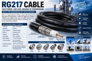
RG217 Cable is a heavy-duty 50 Ohm coaxial RF cable designed for applications that require reliable high-frequency signal transmission, strong mechanical construction, and comparatively high power-handling capability. It is a large-diameter coaxial cable commonly used in radio communication, RF transmission systems, test and measurement equipment, industrial electronics, military systems, and other applications where a robust transmission line is required.
Compared with smaller coaxial cables such as RG58, RG174, and RG316, RG217 has a substantially larger physical construction. Its larger conductor and dielectric structure can provide lower attenuation and greater power-handling capability, making it suitable for applications where minimizing RF loss is important.
RG217 is part of the widely recognized RG/U family of coaxial cables. However, specifications can differ between manufacturers and modern equivalents, so engineers should always verify the actual datasheet before using a particular cable in a critical RF system.
This comprehensive guide explains what RG217 Cable is, how it works, its construction, specifications, electrical characteristics, applications, advantages, limitations, connector options, installation requirements, and factors to consider when selecting RG217 for an RF application.
What Is RG217 Cable?
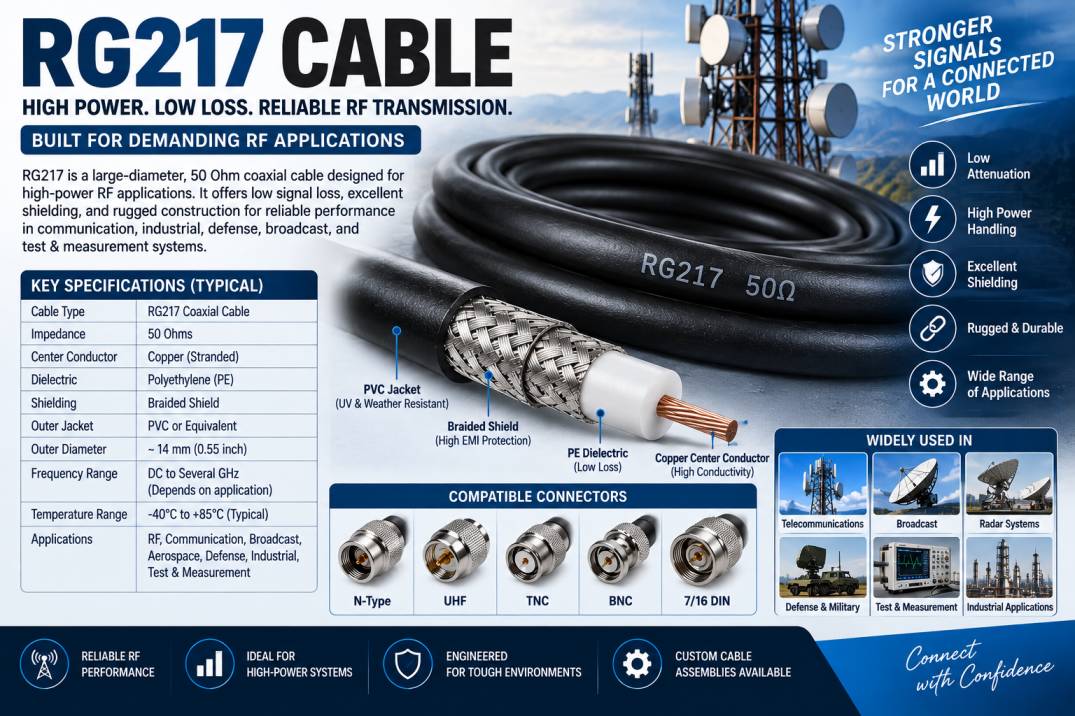
RG217 Cable is a large-diameter, 50 Ohm coaxial cable designed for transmitting RF and microwave signals while providing relatively low attenuation and high power-handling capability.
A typical RG217 construction consists of a center conductor, dielectric insulation, conductive shielding, and protective outer jacket. The large physical diameter of the cable allows the transmission line to handle more RF power and achieve lower losses than many smaller coaxial cable types.
RG217 is commonly associated with applications requiring:
- 50 Ohm characteristic impedance
- Low RF attenuation
- High power handling
- Strong mechanical construction
- Reliable signal transmission
- Good shielding
- Long-term RF performance
- Robust cable construction
The exact construction may vary depending on the manufacturer and cable version. Therefore, product-specific specifications should always be checked before procurement or system design.
How Does RG217 Cable Work?
RG217 Cable operates according to the principles of coaxial transmission.
The RF signal travels through the center conductor, while the surrounding dielectric maintains a controlled distance between the center conductor and outer shield. The outer conductive layer provides the return path and helps contain the electromagnetic field inside the cable.
The coaxial geometry allows the cable to maintain a controlled characteristic impedance. In a properly designed 50 Ohm system, this helps minimize signal reflections caused by impedance mismatch.
When RG217 is terminated with compatible 50 Ohm RF connectors, it creates a controlled transmission path between RF equipment such as transmitters, receivers, antennas, amplifiers, filters, and test instruments.
Construction of RG217 Cable
The construction of RG217 is designed to balance electrical performance, mechanical durability, and power handling.
Center Conductor
The center conductor carries the RF signal.
Depending on the cable manufacturer and construction, the conductor may be made from copper or another highly conductive material.
A larger conductor provides several potential benefits, including lower conductor resistance and improved current-carrying capability.
The conductor design directly influences:
- RF attenuation
- DC resistance
- Power handling
- Flexibility
- Temperature performance
Dielectric Insulation
The dielectric surrounds the center conductor and maintains the correct spacing between the conductor and shield.
A commonly associated dielectric material for RG217 constructions is polyethylene, although modern cable variants can use other materials.
The dielectric affects:
- Characteristic impedance
- Velocity factor
- Capacitance
- Signal propagation
- Dielectric loss
- Temperature performance
Outer Conductor and Shield
The outer conductor provides both the RF return path and electromagnetic shielding.
Depending on the construction, the shield may use a braided or tubular conductive structure.
The shielding helps:
- Reduce electromagnetic interference
- Prevent RF leakage
- Protect the signal from external noise
- Improve electromagnetic compatibility
- Maintain controlled transmission characteristics
Outer Jacket
The outer jacket protects the internal cable structure from physical damage and environmental exposure.
Depending on the intended application, the jacket can be designed for:
- Abrasion resistance
- Moisture resistance
- Temperature resistance
- Chemical resistance
- UV exposure
- Outdoor installation
Key Features of RG217 Cable
RG217 Cable provides several characteristics that make it suitable for demanding RF systems.
- 50 Ohm characteristic impedance
- Large-diameter coaxial construction
- Lower attenuation than many smaller RF cables
- High power-handling capability
- Robust mechanical design
- Reliable RF transmission
- Good shielding performance
- Suitable for RF transmitters
- Suitable for antenna systems
- Useful for laboratory testing
- Available with different RF connectors
- Suitable for custom cable assemblies
RG217 Cable Specifications
The exact specifications of RG217 can vary according to manufacturer, construction, and applicable standard. The following table provides general characteristics rather than a universal datasheet.
| Parameter | RG217 Cable Characteristics |
|---|---|
| Cable Type | Coaxial RF Cable |
| Characteristic Impedance | 50 Ohms |
| Cable Construction | Large-Diameter Coaxial |
| Outer Diameter | Approximately 14 mm, depending on construction |
| Dielectric | Polyethylene or manufacturer-specific material |
| Conductor | Copper or equivalent conductive material |
| Shield | Conductive braided/tubular shield, construction dependent |
| Frequency Range | Application dependent |
| Attenuation | Lower than many small-diameter RF cables |
| Power Handling | High, frequency dependent |
| Flexibility | Moderate to low compared with small RF cables |
| Applications | RF, Radio, Antenna, Test, Industrial and Defense Systems |
These specifications should be confirmed against the manufacturer’s current technical datasheet before use.
RG217 Cable Diameter
One of the most noticeable characteristics of RG217 Cable is its relatively large diameter.
The larger diameter provides room for a substantial center conductor and dielectric structure. This can contribute to lower RF attenuation and greater power-handling capability.
However, the larger physical size also means RG217 requires more installation space than smaller RF cables.
This makes RG217 more appropriate for applications where electrical performance and power handling are more important than minimum cable size.
RG217 Cable Impedance
RG217 is generally designed as a 50 Ohm coaxial cable.
A 50 Ohm impedance is widely used in:
- Radio communication
- RF transmitters
- Antenna systems
- Radar
- Wireless communication
- Microwave systems
- RF test equipment
- Military electronics
Maintaining 50 Ohm impedance throughout the complete RF transmission path is important because impedance discontinuities can cause reflections and reduce system efficiency.
The cable, connectors, adapters, and equipment should therefore be selected with compatible impedance characteristics.
RG217 Cable Frequency Range
The usable frequency range of RG217 depends on the cable’s specific construction and the performance requirements of the RF system.
As RF frequency increases, attenuation generally increases. Therefore, the maximum practical frequency depends not only on the cable itself but also on:
- Cable length
- Connector type
- VSWR requirement
- Insertion loss
- Power level
- Installation conditions
- Required signal quality
Engineers should use manufacturer-provided attenuation and VSWR data at the actual operating frequency instead of relying solely on the RG217 designation.
RG217 Cable Attenuation
Attenuation is the amount of signal power lost as an RF signal travels through the cable.
Cable attenuation is influenced by:
- Frequency
- Cable length
- Conductor material
- Dielectric material
- Cable diameter
- Temperature
- Connector losses
Because RG217 has a relatively large construction, it can provide lower attenuation than many smaller coaxial cables at comparable frequencies.
This characteristic makes it useful for RF transmission paths where cable loss needs to be controlled.
For long RF transmission lines, attenuation should be carefully calculated before selecting the cable.
RG217 Power Handling Capability
One of the important reasons for selecting a large-diameter RF cable such as RG217 is its ability to handle comparatively high RF power.
Power handling depends on:
- Operating frequency
- Cable length
- Ambient temperature
- VSWR
- Cooling conditions
- Cable construction
- Connector rating
A cable operating at a high VSWR can experience increased voltage and current stress, potentially reducing its safe power-handling capability.
Therefore, engineers should never select RG217 based only on a nominal power figure. The manufacturer’s power-handling curve should be evaluated for the actual frequency, VSWR, and environmental conditions.
VSWR and Return Loss
VSWR
Voltage Standing Wave Ratio measures impedance matching within an RF transmission system.
A lower VSWR generally indicates better impedance matching.
Poor connectors, damaged cable geometry, excessive bending, or mismatched components can increase VSWR.
Return Loss
Return loss measures the amount of RF power reflected back toward the source.
Higher return loss generally indicates better impedance matching.
For transmitter and antenna systems, good impedance matching is particularly important because excessive reflected power can reduce efficiency and place additional stress on the transmitter.
Shielding Performance of RG217 Cable
Shielding prevents external electromagnetic energy from interfering with the RF signal and helps prevent RF energy from escaping from the cable.
RG217’s conductive outer structure provides electromagnetic isolation around the center conductor.
Good shielding is particularly important when the cable is installed near:
- Power equipment
- Digital electronics
- Motors
- Industrial machinery
- Other RF transmitters
- Switching power supplies
- High-current electrical wiring
The actual shielding effectiveness depends on the specific cable construction, shield coverage, materials, frequency, and termination method.
Applications of RG217 Cable
RF Transmitter Systems
RG217 can be used to connect RF transmitters to other components in systems where its impedance, attenuation, and power-handling characteristics are appropriate.
Applications may include:
- Radio transmitters
- RF amplifiers
- Communication systems
- Signal distribution equipment
Antenna Systems
RG217 can be used in antenna feeder and interconnection applications where a robust 50 Ohm transmission line is required.
It can connect:
- RF transmitters
- Antennas
- Couplers
- Filters
- Amplifiers
Radio Communication
RG217 is suitable for certain professional and industrial radio communication systems where a larger, lower-loss cable is advantageous.
Military and Defense Electronics
Large coaxial cables can be used in defense RF systems where reliable signal transmission and power handling are important.
Potential applications include:
- Radar equipment
- RF transmitters
- Communication systems
- Electronic test systems
- Antenna systems
Laboratory Test and Measurement
RG217 can be useful for high-power RF testing and laboratory environments.
It may be used with:
- RF signal generators
- Power amplifiers
- RF loads
- Antenna test systems
- Power meters
- RF measurement equipment
Industrial RF Systems
Industrial equipment may require high-power RF transmission for heating, processing, communication, or specialized control systems.
RG217 can be selected when its electrical and mechanical specifications meet the application requirements.
Broadcasting
Radio broadcasting systems may use large coaxial transmission cables for connections between RF transmitters and antenna systems.
RG217 Cable Connector Options
RG217 cable assemblies can be terminated with suitable RF connectors depending on the system requirements.
Possible connector types include:
- N-Type
- UHF
- TNC
- BNC
- 7/16 DIN
- Other high-power RF connectors
Connector selection should consider:
- Frequency
- Power
- Impedance
- Mechanical interface
- Installation environment
- Connector gender
- Cable diameter
Because RG217 is a large cable, the connector must be specifically designed to accommodate its diameter and electrical requirements.
RG217 Cable Assembly
A finished RG217 Cable Assembly consists of the cable terminated with RF connectors at one or both ends.
Custom RG217 assemblies can be manufactured according to application requirements.
Typical customization options include:
- Cable length
- Connector type
- Connector gender
- Straight connectors
- Right-angle connectors where supported
- Heat-shrink protection
- Identification labels
- Protective sleeving
- Connector plating
- Custom termination
Professional cable assembly manufacturing helps ensure proper connector installation and consistent RF performance.
RG217 Cable vs RG58 Cable
| Feature | RG217 Cable | RG58 Cable |
|---|---|---|
| Impedance | 50 Ohms | 50 Ohms |
| Diameter | Large | Smaller |
| Attenuation | Generally lower | Generally higher |
| Power Handling | Higher | Lower |
| Flexibility | Lower | Higher |
| Installation Space | High | Low |
| Mechanical Construction | Heavy-duty | Lightweight |
| Long RF Runs | Better suited | More limited |
| High-Power RF | Suitable | More limited |
| Portable Applications | Less convenient | More convenient |
RG58 is often preferred when flexibility and compact size are priorities, while RG217 can be advantageous where lower loss and higher power handling are required.
RG217 Cable vs RG213 Cable
| Feature | RG217 Cable | RG213 Cable |
|---|---|---|
| Impedance | 50 Ohms | 50 Ohms |
| Construction | Large coaxial cable | Large coaxial cable |
| Diameter | Approximately 14 mm | Approximately 10 mm |
| Flexibility | Moderate to low | Moderate |
| Power Capability | High | High |
| Attenuation | Application dependent | Application dependent |
| RF Applications | High-power RF | High-power RF |
| Antenna Systems | Suitable | Very common |
| Installation Space | Larger | Smaller |
The actual performance difference should be evaluated using manufacturer-specific attenuation and power-handling specifications.
Advantages of RG217 Cable
Low Signal Loss
Its relatively large construction can provide lower attenuation compared with smaller RF cables.
High Power Handling
RG217 can be suitable for RF systems carrying significant power, subject to frequency and installation conditions.
Robust Construction
The larger cable structure provides good mechanical durability.
50 Ohm Impedance
Its 50 Ohm configuration makes it compatible with many professional RF systems.
Reliable RF Transmission
Controlled coaxial geometry supports predictable signal transmission.
Suitable for Antenna Systems
Its electrical characteristics make it useful for certain transmitter-to-antenna applications.
Long-Term Reliability
When correctly selected and installed, RG217 can provide dependable performance in demanding RF environments.
Limitations of RG217 Cable
Despite its advantages, RG217 has several limitations.
- Large physical diameter
- Heavier than smaller RF cables
- Less flexible than RG58 or RG316
- Requires more installation space
- More difficult to route in compact equipment
- Connector installation may require specialized components
- Cable attenuation increases with frequency and length
- Not ideal for applications where extreme flexibility is required
How to Choose the Right RG217 Cable
Selecting RG217 should be based on the complete RF system rather than cable type alone.
Check Impedance
Confirm that the application requires a 50 Ohm transmission line.
Determine Operating Frequency
Verify the cable’s attenuation and VSWR specifications at the actual operating frequency.
Calculate Cable Length
Longer cable runs result in greater signal loss.
Evaluate Power
Check the manufacturer’s power-handling specifications at the operating frequency and expected VSWR.
Select the Correct Connector
Ensure that the connector supports the cable diameter, frequency, impedance, and power level.
Consider Installation Space
RG217 is significantly larger than many common RF cables, so sufficient routing space must be available.
Evaluate Environmental Conditions
Check temperature, moisture, UV exposure, mechanical stress, and chemical exposure.
RG217 Cable Installation Best Practices
Proper installation is important for maintaining RF performance.
Avoid sharp bends.
Follow the manufacturer’s minimum bend radius.
Do not crush or flatten the cable.
Avoid excessive twisting.
Do not pull the cable by the connector.
Use appropriate connector torque.
Keep connector mating surfaces clean.
Support long cable runs mechanically.
Avoid unnecessary cable length.
Protect outdoor connectors against moisture.
Inspect the cable before commissioning.
Improper installation can change cable geometry and negatively affect impedance, VSWR, and attenuation.
Environmental Considerations
The application environment can significantly influence cable selection.
For outdoor installations, consider:
- UV exposure
- Rain
- Humidity
- Temperature
- Wind
- Mechanical movement
For industrial environments, also consider:
- Chemical exposure
- Vibration
- Abrasion
- High temperatures
- Electromagnetic noise
The cable jacket and connectors should be selected according to the environmental conditions.
RG217 Cable for High-Power RF Systems
RG217 is particularly attractive for applications where high RF power and controlled transmission loss are important.
In high-power systems, engineers must evaluate the complete RF path, including:
- Transmitter output
- Cable attenuation
- Connector loss
- VSWR
- Antenna impedance
- Ambient temperature
- Cooling conditions
A cable’s maximum power rating is not a single universal number because safe power handling changes with frequency, temperature, VSWR, and installation conditions.
Maintenance of RG217 Cable
RG217 requires relatively little maintenance when correctly installed.
Recommended maintenance practices include:
- Inspect the outer jacket regularly
- Check connectors for mechanical damage
- Keep RF interfaces clean
- Inspect for corrosion
- Check for excessive bending
- Verify cable support
- Check outdoor seals
- Perform RF measurements when required
In critical systems, periodic VSWR and insertion-loss testing can help identify cable or connector degradation.
Why Professional RG217 Cable Assemblies Matter
The cable itself represents only one part of the RF transmission path. Connector quality and termination workmanship can have a major impact on overall performance.
A professionally manufactured RG217 cable assembly can provide:
- Consistent cable length
- Proper connector installation
- Reliable mechanical termination
- Controlled RF performance
- Better repeatability
- Reduced installation time
For demanding RF systems, custom assemblies can be manufactured according to specific equipment interfaces and installation requirements.
Future of Large-Diameter RF Cables
The growth of high-power wireless communication, broadcasting, radar, defense systems, industrial RF equipment, and specialized test systems continues to create demand for robust RF transmission lines.
At the same time, newer low-loss coaxial technologies are providing improved performance with reduced size and weight. As a result, RG217 and similar large-diameter coaxial cables are likely to remain relevant where their combination of power handling, mechanical robustness, and RF performance provides a practical advantage.
Conclusion
RG217 Cable is a large-diameter 50 Ohm coaxial RF cable designed for applications requiring reliable RF signal transmission, relatively low attenuation, and high power-handling capability. Its robust construction makes it particularly suitable for professional radio communication, antenna systems, RF transmitters, broadcasting, defense electronics, industrial RF systems, and laboratory test equipment.
The larger diameter of RG217 provides advantages in power handling and transmission performance compared with many smaller RF cables, but it also results in greater weight, reduced flexibility, and higher installation-space requirements.
When selecting RG217 Cable, engineers should evaluate characteristic impedance, operating frequency, attenuation, VSWR, return loss, power handling, cable length, connector compatibility, environmental conditions, and installation requirements. The actual manufacturer’s datasheet should always be used for final system design because specifications can vary between cable constructions.
With correct selection, professional termination, and proper installation, RG217 Cable can provide a dependable RF transmission solution for demanding high-power and communication applications.
Frequently Asked Questions About RG217 Cable
1. What is RG217 Cable?
RG217 Cable is a large-diameter 50 Ohm coaxial RF cable designed for reliable signal transmission, relatively low attenuation, and high power-handling applications.
2. What is the impedance of RG217 Cable?
RG217 Cable is generally designed with a 50 Ohm characteristic impedance, making it suitable for many professional RF and communication systems.
3. What is RG217 Cable used for?
RG217 is used in RF transmitters, antenna systems, radio communication, broadcasting, defense electronics, industrial RF equipment, and laboratory test systems.
4. Is RG217 a high-power RF cable?
Yes. RG217’s large construction allows it to handle comparatively high RF power, although the safe power level depends on frequency, VSWR, temperature, cable length, and the specific manufacturer’s specifications.
5. Is RG217 Cable flexible?
RG217 has some flexibility but is considerably less flexible than smaller cables such as RG58 and RG316. Its larger diameter makes it more suitable for fixed or semi-permanent installations.
6. What is the difference between RG217 and RG58?
RG217 is significantly larger and generally provides greater power-handling capability and lower attenuation, while RG58 is smaller, lighter, and more flexible.
7. What is the difference between RG217 and RG213?
Both are large 50 Ohm coaxial cables used for RF applications. RG217 is generally larger in diameter, while RG213 is more compact and widely used for antenna and radio communication applications.
8. What connectors are used with RG217 Cable?
Depending on the application, RG217 can be terminated with suitable RF connectors such as N-Type, UHF, TNC, BNC, 7/16 DIN, and other compatible high-power connectors.
9. Can RG217 be used for antenna systems?
Yes. RG217 can be used in antenna feeder and RF interconnection applications when its frequency, attenuation, power, impedance, and environmental specifications meet the system requirements.
10. Is RG217 suitable for long-distance RF transmission?
Its relatively low attenuation compared with many smaller cables can make it suitable for longer RF runs, but the actual suitability depends on operating frequency, cable length, required signal level, and allowable loss.
11. What affects RG217 Cable power handling?
Power handling depends on operating frequency, VSWR, ambient temperature, cable construction, cooling, and cable length. Always use the manufacturer’s power-handling data for system design.
12. Can RG217 Cable be customized?
Yes. RG217 cable assemblies can be customized by length, connector type, connector gender, termination style, labeling, protective sleeving, and other application requirements.
13. Is RG217 suitable for outdoor use?
RG217 can be used in outdoor applications when the selected cable jacket and connector assembly are rated for the environmental conditions. Proper weatherproofing may be required.
14. Why is 50 Ohm impedance important?
Maintaining 50 Ohm impedance helps minimize reflections and VSWR when the cable is connected to compatible 50 Ohm RF equipment.
15. How do I choose the right RG217 Cable?
Consider operating frequency, cable length, attenuation, VSWR, power handling, impedance, connector type, installation space, temperature, environmental exposure, and the manufacturer’s technical specifications.