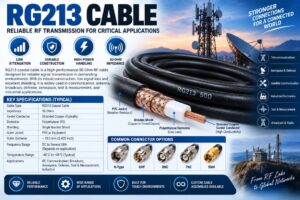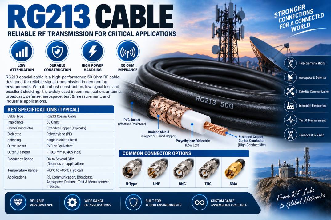
RG213 Cable is a widely used 50 Ohm coaxial RF cable designed for reliable transmission of radio frequency signals in communication, radio, antenna, laboratory, industrial, and electronic systems. Its relatively large diameter, robust construction, and dependable electrical performance make it a popular choice for applications where durability, signal integrity, and power handling are important.
RG213 is commonly used as an RF transmission cable between radios, transmitters, antennas, amplifiers, test equipment, and other RF components. Compared with smaller coaxial cables such as RG58 and RG174, RG213 has a larger physical construction that generally provides lower attenuation and greater power-handling capability.
The cable typically consists of a center conductor, dielectric insulation, braided shield, and protective outer jacket. Its 50 Ohm characteristic impedance makes it compatible with a wide range of professional RF and wireless communication systems.
RG213 Cable is particularly valuable in applications where cable performance must remain reliable over longer transmission distances than those typically associated with miniature RF cables.
This comprehensive guide explains what RG213 Cable is, how it works, its construction, specifications, electrical characteristics, applications, advantages, limitations, connector options, installation requirements, and important factors to consider before selecting an RG213 cable assembly.
What Is RG213 Cable?
RG213 Cable is a 50 Ohm coaxial cable designed for RF signal transmission. It is a relatively large-diameter cable commonly used in radio communication, antenna systems, RF laboratories, broadcasting, industrial electronics, and other high-frequency applications.
The larger construction of RG213 allows it to provide comparatively low attenuation and good power-handling capability while maintaining the controlled impedance required by RF systems.
A typical RG213 Cable consists of:
- Center conductor
- Polyethylene dielectric
- Braided metallic shield
- Protective outer jacket
The cable’s coaxial construction allows the electromagnetic field to remain concentrated between the center conductor and the outer conductor. This helps provide controlled impedance and reduces unwanted electromagnetic radiation.
RG213 is generally associated with a 50 Ohm characteristic impedance, making it suitable for many RF transmitters, receivers, radios, antennas, and test instruments.
How Does RG213 Cable Work?
RG213 Cable operates using the principle of coaxial transmission.
The center conductor carries the RF signal from the source to the destination. The dielectric surrounds the conductor and maintains a controlled distance between the center conductor and the outer shield.
The outer conductive shield serves as the return path for the RF signal and also provides electromagnetic shielding.
The coaxial arrangement helps maintain a consistent characteristic impedance along the cable.
When the cable is connected to compatible 50 Ohm equipment using suitable RF connectors, it provides a controlled transmission path that helps reduce signal reflections and maintain RF system efficiency.
Cable performance is affected by several factors, including frequency, cable length, connector quality, installation technique, temperature, and impedance matching.
Construction of RG213 Cable
The construction of RG213 is designed to provide a balance between RF performance, mechanical durability, flexibility, and power handling.
Center Conductor
The center conductor carries the RF signal through the cable.
Traditional RG213 constructions commonly use a stranded copper center conductor. The conductor design provides good electrical conductivity while maintaining a degree of flexibility.
The center conductor affects:
- RF attenuation
- DC resistance
- Power handling
- Flexibility
- Temperature performance
High-quality conductor materials help minimize resistive losses and improve long-term reliability.
Dielectric Material
The dielectric surrounds the center conductor and maintains the required spacing between the center conductor and shield.
Polyethylene is commonly associated with RG213 construction.
The dielectric influences several important characteristics:
- Characteristic impedance
- Velocity factor
- Capacitance
- Signal propagation
- Dielectric loss
- Temperature performance
The consistency of the dielectric geometry is important because changes in conductor spacing can affect impedance and RF performance.
Braided Shield
The braided outer conductor provides the RF return path and electromagnetic shielding.
Depending on the cable construction, the braid may be manufactured using copper or tinned copper.
The shield helps:
- Reduce electromagnetic interference
- Reduce signal leakage
- Protect the RF signal from external noise
- Improve electromagnetic compatibility
- Provide mechanical protection
Shielding effectiveness depends on braid material, braid coverage, frequency, cable construction, and connector termination.
Outer Jacket
The outer jacket protects the internal cable structure from mechanical and environmental damage.
Depending on the specific cable version, the jacket may provide resistance to:
- Abrasion
- Moisture
- Temperature
- Chemicals
- UV exposure
For outdoor RF installations, an appropriate weather-resistant cable and properly sealed connectors should be selected.
Key Features of RG213 Cable
RG213 Cable offers several characteristics that make it suitable for professional RF systems.
- 50 Ohm characteristic impedance
- Large-diameter coaxial construction
- Good RF signal transmission
- Relatively low attenuation
- Good power-handling capability
- Strong mechanical construction
- Reliable shielding
- Flexible compared with rigid transmission lines
- Suitable for radio communication
- Suitable for antenna systems
- Useful in RF laboratories
- Compatible with many RF connectors
- Available in custom cable assemblies
- Suitable for indoor and outdoor RF applications when properly specified
RG213 Cable Specifications
The exact specifications of RG213 can vary between manufacturers. The following table provides representative characteristics for understanding the cable.
| Parameter | Typical RG213 Cable Characteristics |
|---|---|
| Cable Type | Coaxial RF Cable |
| Characteristic Impedance | 50 Ohms |
| Center Conductor | Stranded Copper, commonly |
| Dielectric | Polyethylene, commonly |
| Shield | Braided Copper/Tinned Copper |
| Outer Jacket | PVC or application-specific material |
| Outer Diameter | Approximately 10.3 mm |
| Frequency Range | Application dependent |
| Attenuation | Lower than many smaller coaxial cables |
| Power Handling | High, frequency dependent |
| Flexibility | Moderate |
| Applications | RF, Radio, Antenna, Broadcast, Test & Measurement |
These values are general reference characteristics rather than a universal RG213 datasheet. Always verify the manufacturer’s current technical specifications before using the cable in a critical RF application.
RG213 Cable Impedance
RG213 is generally designed with a 50 Ohm characteristic impedance.
50 Ohm coaxial systems are widely used for:
- Radio communication
- RF transmitters
- Antenna systems
- Radar
- Wireless communication
- Satellite equipment
- RF test equipment
- Defense electronics
- Industrial RF systems
Maintaining a consistent 50 Ohm transmission path helps minimize signal reflections and standing waves.
The complete RF system should therefore use compatible impedance across the cable, connectors, adapters, antennas, and equipment.
RG213 Cable Diameter
RG213 is significantly larger than miniature RF cables such as RG174 and RG316.
Its larger diameter provides several potential advantages, including:
- Lower conductor resistance
- Lower attenuation
- Better power handling
- Improved mechanical durability
However, the larger diameter also makes RG213 heavier and less flexible than smaller coaxial cables.
This means RG213 is generally better suited to fixed or semi-permanent installations rather than applications requiring frequent movement.
RG213 Cable Frequency Range
RG213 can be used in a wide range of RF applications, but the actual usable frequency range depends on the manufacturer’s cable construction and the required performance.
Frequency performance is influenced by:
- Cable length
- Attenuation
- VSWR
- Return loss
- Connector type
- Power level
- Environmental conditions
At higher frequencies, attenuation generally increases. Therefore, engineers should use manufacturer-provided attenuation and VSWR data when designing RF systems.
RG213 Cable Attenuation
Attenuation refers to the reduction in RF signal power as the signal travels through the cable.
RG213’s larger construction generally provides lower attenuation than smaller coaxial cables at comparable frequencies.
Cable attenuation depends on:
- Operating frequency
- Cable length
- Conductor material
- Dielectric material
- Cable diameter
- Temperature
- Connector losses
For longer RF transmission paths, attenuation becomes especially important.
Engineers should calculate the expected total cable loss before selecting RG213 for an application.
RG213 Cable Power Handling
RG213 is often selected for RF applications requiring relatively high power handling compared with smaller coaxial cables.
Power-handling capability depends on:
- Operating frequency
- VSWR
- Cable length
- Ambient temperature
- Cooling conditions
- Cable construction
A high VSWR can increase voltage and current stress inside the cable and reduce the safe power-handling capability.
Therefore, engineers should always use manufacturer-specific power-handling data rather than relying on a generic power rating.
VSWR and Return Loss
What Is VSWR?
Voltage Standing Wave Ratio measures the degree of impedance mismatch within an RF transmission system.
Lower VSWR generally indicates better impedance matching.
VSWR can increase due to:
- Incorrect connectors
- Poor connector installation
- Damaged cable
- Excessive bending
- Impedance mismatches
- Poor-quality adapters
What Is Return Loss?
Return loss measures the amount of RF power reflected back toward the signal source.
Higher return loss generally indicates better impedance matching.
Both VSWR and return loss should be evaluated at the actual operating frequency when designing a precision RF system.
Shielding Performance of RG213 Cable
The braided shield of RG213 provides electromagnetic protection around the center conductor.
Shielding is particularly important when the cable is installed near sources of electrical noise.
Examples include:
- Switching power supplies
- Motors
- Industrial equipment
- Digital electronics
- High-current cables
- RF transmitters
- Electrical control systems
Good shielding can reduce unwanted signal coupling and help maintain signal integrity.
The actual shielding effectiveness depends on the braid construction, coverage, material, frequency, cable design, and connector termination.
Applications of RG213 Cable
RG213 Cable is used in many RF and communication applications.
Radio Communication
RG213 can be used to connect radio equipment to antennas and other RF components.
Applications include:
- Amateur radio
- Professional radio
- Industrial communication
- Base radio systems
- Communication test equipment
Antenna Systems
RG213 is widely used for antenna feeder and RF transmission applications where its 50 Ohm impedance and comparatively low attenuation are suitable.
It can connect:
- RF transmitters
- Antennas
- Amplifiers
- Filters
- Couplers
- RF switches
Broadcasting
Broadcasting systems can use large coaxial cables for RF signal distribution and equipment interconnection.
RG213 can be used where its power and frequency specifications meet the requirements.
RF Test and Measurement
RG213 can be useful in RF laboratories and testing environments.
Applications include:
- Signal generators
- Spectrum analyzers
- RF power meters
- Network analyzers
- RF loads
- Antenna testing
- Calibration systems
Military and Defense
RG213 and similar robust coaxial cables can be used in defense communication and RF systems where reliable signal transmission is important.
Applications can include:
- Communication equipment
- Radar support systems
- RF test equipment
- Antenna systems
- Electronic instrumentation
Aerospace Electronics
Aerospace systems can require reliable RF cable assemblies for:
- Communication
- Navigation
- RF instrumentation
- Test equipment
- Avionics
Cable selection must consider weight, temperature, vibration, and environmental requirements.
Industrial RF Systems
Industrial RF equipment can use RG213 for signal transmission where its size, flexibility, attenuation, and power handling are appropriate.
Satellite Communication
RG213 can be used in certain ground-based satellite communication and RF equipment applications where the cable’s frequency performance is adequate.
Common RG213 Cable Connector Types
RG213 Cable assemblies can be terminated with several RF connector types.
Common connector options include:
- N-Type
- UHF
- TNC
- BNC
- SMA
- 7/16 DIN
- Other application-specific RF connectors
Connector selection should consider:
- Frequency
- Power
- Impedance
- Cable diameter
- Mechanical requirements
- Environmental conditions
The connector must be properly matched to the cable and RF system.
RG213 Cable Assembly
An RG213 Cable Assembly consists of RG213 cable terminated with compatible RF connectors.
Custom cable assemblies can be manufactured according to application requirements.
Common customization options include:
- Cable length
- Connector type
- Connector gender
- Straight connectors
- Right-angle connectors where available
- Heat-shrink protection
- Cable identification
- Protective sleeving
- Connector plating
- Custom termination
A professionally manufactured cable assembly can help provide consistent electrical and mechanical performance.
RG213 Cable vs RG214 Cable
| Feature | RG213 Cable | RG214 Cable |
|---|---|---|
| Impedance | 50 Ohms | 50 Ohms |
| Shielding | Single shield, commonly | Double shield |
| EMI Protection | Good | Enhanced |
| Center Conductor | Copper, commonly | Silver-plated copper, commonly |
| Dielectric | Polyethylene, commonly | PTFE, commonly |
| Diameter | Approximately 10.3 mm | Approximately 10.8 mm |
| Flexibility | Moderate | Moderate |
| Typical Applications | Radio, Antenna, RF | Defense, Aerospace, Test, RF |
| Shielding Requirement | Standard | Higher |
RG213 is commonly selected for general RF and antenna applications, while RG214 is often preferred where enhanced shielding and PTFE-based construction are required.
RG213 Cable vs RG58 Cable
| Feature | RG213 Cable | RG58 Cable |
|---|---|---|
| Impedance | 50 Ohms | 50 Ohms |
| Diameter | Larger | Smaller |
| Attenuation | Generally lower | Generally higher |
| Power Handling | Higher | Lower |
| Flexibility | Moderate | Higher |
| Weight | Higher | Lower |
| Installation Space | Larger | Smaller |
| Long RF Runs | Better suited | More limited |
| High-Power Applications | More suitable | More limited |
| Portable Applications | Less convenient | More convenient |
RG58 is useful when compact size and flexibility are important, while RG213 is advantageous when lower attenuation and greater power handling are required.
RG213 Cable vs RG316 Cable
| Feature | RG213 | RG316 |
|---|---|---|
| Impedance | 50 Ohms | 50 Ohms |
| Diameter | Large | Small |
| Flexibility | Moderate | High |
| Attenuation | Generally lower | Generally higher |
| Power Handling | Higher | Lower |
| Weight | Higher | Lower |
| Compact Applications | Limited | Excellent |
| RF Assembly Applications | Excellent | Excellent |
| Long RF Runs | Better suited | Less suitable |
RG316 is commonly selected for compact electronic systems, while RG213 is more suitable for applications requiring a larger, lower-loss, higher-power coaxial cable.
Advantages of RG213 Cable
Low RF Attenuation
The relatively large cable construction helps provide lower attenuation than many smaller coaxial cables.
High Power Handling
RG213 can support comparatively high RF power when operated within the manufacturer’s specified conditions.
50 Ohm Impedance
Its 50 Ohm impedance makes it compatible with many professional RF systems.
Robust Construction
The larger physical structure provides good mechanical durability.
Reliable Signal Transmission
The controlled coaxial geometry supports consistent RF signal transmission.
Wide Range of Applications
RG213 can be used in communication, antenna, broadcasting, laboratory, industrial, aerospace, and defense systems.
Custom Cable Assemblies
RG213 can be terminated with different connectors and manufactured in custom lengths.
Limitations of RG213 Cable
RG213 is not suitable for every RF application.
Its limitations include:
- Larger diameter than RG58 and RG316
- Heavier than miniature coaxial cables
- Less flexible than small RF cables
- Requires more installation space
- More difficult to route in compact equipment
- Cable loss increases with frequency
- Connector quality significantly affects system performance
- Not ideal for applications requiring continuous movement
For compact electronics, smaller RF cables may be more appropriate.
For extremely long RF transmission paths, specialized low-loss coaxial cables may provide better performance.
How to Choose the Right RG213 Cable
Selecting the correct RG213 Cable requires evaluating the complete RF system.
Check the Impedance
Verify that the application requires a 50 Ohm transmission line.
Determine the Operating Frequency
Check attenuation, VSWR, and return loss at the actual operating frequency.
Calculate Cable Length
Longer cables introduce more signal loss, so cable length should be minimized where practical.
Evaluate Power Requirements
Check the manufacturer’s power-handling specifications for the intended frequency, VSWR, and environmental conditions.
Select the Correct Connector
Choose connectors that match the equipment interface and cable construction.
Consider Installation Space
Make sure there is enough space to route and support the relatively large RG213 cable.
Check Environmental Requirements
Consider:
- Temperature
- Humidity
- UV exposure
- Moisture
- Vibration
- Chemicals
- Mechanical stress
RG213 Cable Installation Best Practices
Correct installation helps maintain RF performance.
Avoid sharp bends.
Follow the manufacturer’s recommended minimum bend radius.
Do not crush or flatten the cable.
Avoid excessive twisting.
Do not pull the cable using the connector.
Use the correct connector installation procedure.
Apply appropriate connector torque.
Keep connector mating surfaces clean.
Avoid unnecessary cable length.
Provide mechanical support for long cable runs.
Protect outdoor connections from moisture.
Inspect the cable before installation.
Poor installation can change cable geometry and negatively affect impedance, VSWR, and attenuation.
RG213 Cable Testing
Professional RG213 cable assemblies can be tested to verify electrical and mechanical performance.
Common tests include:
- Continuity
- Insulation resistance
- Insertion loss
- Return loss
- VSWR
- Connector inspection
- Dimensional inspection
- High-voltage testing where applicable
Testing is particularly important in aerospace, defense, telecommunications, laboratory, and other critical RF applications.
Custom RG213 Cable Assembly
Custom RG213 Cable Assemblies are useful when standard cable lengths or connector combinations do not meet an application’s requirements.
Customization can include:
- Specific cable length
- Connector type
- Connector gender
- Straight connector
- Right-angle connector where supported
- Heat-shrink tubing
- Identification labels
- Protective sleeving
- Connector plating
- Special termination
A custom cable assembly can simplify installation and provide a more consistent connection between RF equipment.
Environmental Considerations
Environmental conditions should be evaluated before selecting RG213.
For outdoor applications, consider:
- Rain
- Humidity
- UV radiation
- Temperature
- Wind
- Mechanical movement
For industrial environments, additional factors include:
- Chemicals
- Vibration
- Abrasion
- High temperature
- Electromagnetic interference
The cable jacket and connectors should be selected to match the expected operating environment.
Maintenance of RG213 Cable
RG213 generally requires little maintenance when installed correctly.
Recommended maintenance practices include:
- Inspect the cable jacket
- Check connectors for damage
- Clean RF mating interfaces
- Inspect for corrosion
- Check for excessive bending
- Verify cable support
- Inspect outdoor weather seals
- Perform RF measurements when necessary
For critical RF installations, periodic VSWR and insertion-loss testing can help identify cable degradation.
Why Use RG213 Cable for RF Applications?
RG213 provides a useful combination of:
- 50 Ohm impedance
- Large conductor structure
- Good RF performance
- Relatively low attenuation
- High power-handling capability
- Robust mechanical construction
- Wide application compatibility
These characteristics make RG213 particularly useful for RF transmission paths where a smaller cable may not provide the desired loss or power performance.
Future of RG213 and Coaxial RF Cables
The growth of wireless communication, professional radio, broadcasting, radar, satellite systems, industrial RF equipment, and advanced test systems continues to create demand for reliable coaxial transmission lines.
At the same time, newer low-loss cables are being developed with improved attenuation, lighter weight, better shielding, and higher-frequency performance.
RG213 remains relevant because it provides a practical combination of robust construction, 50 Ohm impedance, good power handling, and relatively low attenuation for many RF applications.
Conclusion
RG213 Cable is a robust 50 Ohm coaxial RF cable widely used for radio communication, antenna systems, broadcasting, RF test equipment, industrial electronics, aerospace, defense, and other high-frequency applications. Its larger diameter provides advantages in attenuation and power handling compared with many smaller coaxial cables, while its controlled coaxial construction supports reliable RF signal transmission.
The cable’s performance depends on its specific construction, operating frequency, cable length, connector quality, installation method, temperature, and environmental conditions. For this reason, engineers should always refer to the manufacturer’s datasheet when selecting RG213 for a critical application.
RG213 is particularly suitable when a system requires a durable RF cable with good signal transmission characteristics and comparatively high power-handling capability. For compact equipment, RG316 or other miniature RF cables may be more suitable, while very long transmission paths may require specialized low-loss coaxial cables.
With appropriate cable selection, professional connector termination, correct installation, and periodic inspection, RG213 Cable can provide dependable and long-lasting RF connectivity across a wide range of communication and electronic systems.
Frequently Asked Questions About RG213 Cable
1. What is RG213 Cable?
RG213 Cable is a 50 Ohm coaxial RF cable designed for reliable radio frequency signal transmission. It is commonly used in radio communication, antenna systems, broadcasting, RF testing, industrial electronics, aerospace, and defense.
2. What is the impedance of RG213 Cable?
RG213 is generally designed with a 50 Ohm characteristic impedance, making it compatible with many RF transmitters, receivers, antennas, radios, and test instruments.
3. What is RG213 Cable used for?
RG213 is used for antenna feeders, radio communication, RF transmitters, broadcasting, laboratory testing, industrial RF systems, aerospace electronics, defense equipment, and other RF applications.
4. Is RG213 a low-loss cable?
RG213 can provide relatively low attenuation compared with smaller coaxial cables, but the actual loss depends on frequency, cable construction, length, and manufacturer specifications.
5. Can RG213 handle high RF power?
Yes. RG213 is commonly used for relatively high-power RF applications. However, the allowable power depends on frequency, VSWR, temperature, cooling, cable construction, and manufacturer specifications.
6. What is the difference between RG213 and RG214?
RG213 is commonly associated with a single braided shield and polyethylene dielectric, while RG214 is commonly manufactured with double shielding and PTFE dielectric. RG214 is often selected when enhanced shielding is required.
7. What is the difference between RG213 and RG58?
RG213 has a larger diameter and generally offers lower attenuation and greater power handling than RG58. RG58 is smaller, lighter, and more flexible.
8. What is the difference between RG213 and RG316?
RG213 is much larger and generally offers better power handling and lower attenuation, while RG316 is smaller and more flexible, making it better suited to compact RF assemblies.
9. What connectors are commonly used with RG213?
Common connector options include N-Type, UHF, TNC, BNC, SMA, and 7/16 DIN, depending on the application, frequency, power, and cable assembly requirements.
10. Can RG213 Cable be used for antenna systems?
Yes. RG213 is widely suitable for antenna feeder and RF interconnection applications when its impedance, frequency, attenuation, power, and environmental specifications meet the system requirements.
11. Is RG213 suitable for outdoor applications?
Yes, when an appropriate jacket and connector assembly are selected for outdoor conditions. Proper weatherproofing may be required to protect the connection from moisture and environmental exposure.
12. Can RG213 Cable be customized?
Yes. RG213 cable assemblies can be customized by cable length, connector type, connector gender, termination configuration, labeling, protective sleeving, and other application requirements.
13. What affects RG213 Cable signal loss?
Signal loss is affected by operating frequency, cable length, conductor material, dielectric construction, temperature, connector losses, and cable condition.
14. Why is 50 Ohm impedance important for RG213?
50 Ohm impedance allows RG213 to interface correctly with many RF systems. Maintaining impedance matching helps reduce signal reflections, VSWR, and transmission losses.
15. How do I select the right RG213 Cable?
Consider operating frequency, cable length, attenuation, VSWR, return loss, power handling, impedance, connector type, temperature range, flexibility, shielding, and environmental conditions before selecting RG213.
16. How should RG213 Cable be installed?
RG213 should be installed without sharp bends, crushing, excessive twisting, or unnecessary mechanical stress. The manufacturer’s recommended bend radius and connector installation requirements should always be followed.
17. Is RG213 suitable for RF testing?
Yes. RG213 cable assemblies can be used in RF laboratories for connections involving signal generators, spectrum analyzers, power meters, network analyzers, RF loads, and antenna test equipment when their specifications are appropriate.
18. Why choose RG213 over a smaller RF cable?
RG213 can be preferred when lower attenuation, greater power handling, and robust mechanical construction are more important than minimum size and maximum flexibility.