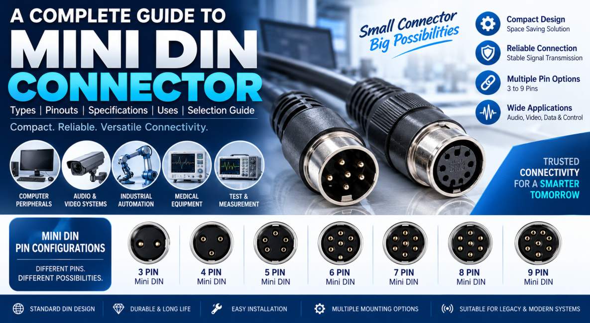
Mini DIN connectors are compact, circular, multi-pin electrical connectors designed for reliable transmission of electrical signals, data, audio, video, control signals, and low-voltage power. The term Mini DIN refers to a family of connectors based on the DIN connector format but manufactured in a smaller and more compact form factor.
Mini DIN connectors have been used across computer peripherals, audio and video equipment, industrial control systems, medical electronics, communication equipment, security systems, and test and measurement instruments. Although newer interfaces such as USB-C, HDMI, and Ethernet have replaced Mini DIN connectors in many modern consumer applications, Mini DIN remains an important connectivity solution in industrial equipment, legacy systems, specialized electronics, and applications where a compact multi-pin interface is required.
The popularity of Mini DIN connectors comes from their compact size, multiple contact configurations, keyed mechanical design, relatively secure connection, and ability to accommodate several electrical circuits within a small connector body.
This comprehensive Mini DIN connector guide explains what a Mini DIN connector is, how it works, its construction, types, pin configurations, specifications, applications, advantages, limitations, wiring considerations, and how to select the right Mini DIN connector for a particular application.
What Is a Mini DIN Connector?
A Mini DIN connector is a small circular electrical connector with multiple pins arranged inside a keyed circular housing. It is commonly used to connect cables to electronic equipment and transfer one or more electrical signals between two devices.
Mini DIN connectors are available in different pin configurations, including 3-pin, 4-pin, 5-pin, 6-pin, 7-pin, 8-pin, and 9-pin versions. Each configuration has a different contact arrangement and can be designed for specific applications.
The connector’s keyed design helps ensure that the plug is inserted into the socket in the correct orientation. This reduces the possibility of incorrect pin alignment and helps protect the contacts from accidental damage.
A Mini DIN connector can be manufactured in cable-mount, panel-mount, PCB-mount, right-angle, straight, shielded, and ruggedized configurations.
Why Is It Called Mini DIN?
The name combines “Mini” with “DIN.”
DIN stands for Deutsches Institut für Normung, the German standards organization associated with various technical standards. Mini DIN connectors were developed as compact alternatives to larger DIN connector formats.
The Mini DIN family became particularly well known through applications such as the six-pin connector used for PS/2 keyboards and mice and the four-pin connector commonly associated with S-Video.
However, Mini DIN should not be treated as a single connector with one universal pinout. Different Mini DIN configurations can have different electrical functions and pin assignments.
How Does a Mini DIN Connector Work?
A Mini DIN connector works by establishing electrical contact between corresponding contacts in the male plug and female socket.
The plug contains multiple metal contacts. When inserted into the mating receptacle, these contacts connect with corresponding terminals. Each contact can carry a particular electrical function depending on the equipment design.
For example, a connector may use individual pins for:
- Power supply
- Ground
- Data
- Clock
- Audio
- Video
- Control signals
- Sensor signals
The circular housing provides mechanical support, while the keyed design helps prevent incorrect insertion.
In shielded versions, the metallic shell or shielding structure can also help reduce electromagnetic interference and unwanted signal coupling.
Construction of a Mini DIN Connector
A Mini DIN connector consists of several important mechanical and electrical components.
Contact Pins
The contact pins are responsible for carrying electrical signals between the connector and connected equipment.
Contacts may be manufactured from conductive copper alloys such as brass or phosphor bronze. Contact surfaces can be plated with materials such as nickel or gold depending on the required electrical performance, corrosion resistance, and durability.
Insulating Body
The insulating body separates the individual contacts and prevents unwanted electrical connections between adjacent pins.
Engineering plastics and thermoplastic materials are commonly used because they provide electrical insulation and mechanical stability.
Outer Housing
The outer housing protects the internal contacts and provides mechanical support.
Depending on the connector design, the housing may be made from molded polymer, metal, or a combination of materials.
Keying Structure
Mini DIN connectors normally include a keyed mechanical arrangement. This helps establish the correct orientation between the plug and socket.
Strain Relief
Cable-mounted Mini DIN connectors may incorporate strain relief to reduce mechanical stress at the point where the cable enters the connector.
Mini DIN Connector Types
Mini DIN connectors can be classified according to their pin count, mounting configuration, connector orientation, and application.
Mini DIN 3-Pin Connector
A three-pin Mini DIN connector contains three electrical contacts.
Typical functions may include:
- Power
- Ground
- Signal
Applications can include sensors, compact control equipment, and specialized electronic systems.
The exact pin assignment depends on the equipment and connector design.
Mini DIN 4-Pin Connector
The four-pin Mini DIN connector is one of the best-known configurations.
It became particularly associated with S-Video applications, where separate conductors can be used for luminance and chrominance signals along with their corresponding grounds.
Other applications may include cameras, video equipment, industrial devices, and specialized communication equipment.
Mini DIN 5-Pin Connector
Five-pin Mini DIN connectors can be used for various control, audio, instrumentation, and industrial applications.
Because connector pinouts can vary between equipment manufacturers, the pin assignment should always be confirmed using the product documentation.
Mini DIN 6-Pin Connector
The six-pin Mini DIN connector became widely recognized because of its use with PS/2 keyboards and mice.
It can also be found in certain industrial, control, and legacy electronic systems.
A six-pin connector provides additional contacts compared with four- or five-pin versions, allowing several signal and power connections within a relatively compact housing.
Mini DIN 7-Pin Connector
Seven-pin Mini DIN connectors are used in specialized applications where additional signal contacts are required.
Potential applications include:
- Video equipment
- CCTV systems
- Industrial electronics
- Communication equipment
- Specialized control systems
The pinout is application-specific and should not be assumed based only on the connector’s physical appearance.
Mini DIN 8-Pin Connector
Eight-pin Mini DIN connectors provide eight electrical contacts and can support multiple signal paths.
They may be used in:
- Serial communication equipment
- Industrial controllers
- Laboratory instruments
- Audio systems
- Specialized electronic equipment
Mini DIN 9-Pin Connector
Nine-pin Mini DIN connectors provide additional contacts for complex signal and control requirements.
They can be used in industrial electronics, instrumentation, medical equipment, communication equipment, and other specialized systems.
Mini DIN Connector Pin Configuration
One of the most important points to understand about Mini DIN connectors is that the physical pin count does not automatically define the electrical pinout.
Two connectors with the same number of pins can have completely different electrical assignments depending on their application.
The following table provides examples of common application categories rather than a universal pinout.
Mini DIN Pin Configuration Chart
| Mini DIN Type | Pin Count | Common Application | Typical Signal Categories |
|---|---|---|---|
| Mini DIN 3 | 3 | Sensors and controls | Power, ground, signal |
| Mini DIN 4 | 4 | S-Video and video | Video and ground |
| Mini DIN 5 | 5 | Industrial and audio equipment | Signal, control, power |
| Mini DIN 6 | 6 | PS/2 and legacy systems | Data, clock, power, ground |
| Mini DIN 7 | 7 | Video and specialized equipment | Video, control, ground |
| Mini DIN 8 | 8 | Communication and control | Data, control, power |
| Mini DIN 9 | 9 | Industrial and specialized electronics | Multiple signals |
Always verify the manufacturer’s official pinout before connecting a Mini DIN cable because connector geometry alone does not guarantee electrical compatibility.
Mini DIN Connector Specifications
Mini DIN connector specifications vary considerably according to the manufacturer and application.
Important specifications include:
- Number of contacts
- Contact material
- Contact plating
- Rated voltage
- Rated current
- Contact resistance
- Insulation resistance
- Operating temperature
- Mating cycles
- Cable diameter
- Mounting method
- Shielding
- Environmental protection
Typical Specification Categories
| Specification | Typical Consideration |
|---|---|
| Number of Pins | 3 to 9 commonly encountered |
| Contact Material | Copper alloy, brass, phosphor bronze |
| Contact Plating | Nickel or gold depending on design |
| Insulation | Engineering thermoplastic |
| Mounting | Cable, PCB or panel mount |
| Connector Orientation | Straight or right angle |
| Shielding | Optional or application-dependent |
| Operating Temperature | Depends on connector construction |
| Mating Cycles | Depends on manufacturer and series |
| Impedance | Application-dependent |
The exact ratings should always be taken from the individual connector manufacturer’s datasheet.
Mini DIN Connector Mounting Types
Cable Mount Mini DIN Connector
Cable mount Mini DIN connectors are installed directly onto cables.
They are frequently used when a detachable cable connection is required.
Typical applications include:
- Audio cables
- Computer peripherals
- Medical equipment
- Industrial control cables
- Specialized communication cables
Panel Mount Mini DIN Connector
Panel mount connectors are installed through an equipment enclosure.
They provide a fixed interface between external cables and internal electronic circuits.
Applications include:
- Control panels
- Industrial equipment
- Test instruments
- Communication equipment
- Security systems
PCB Mount Mini DIN Connector
PCB-mounted Mini DIN connectors are soldered or otherwise mounted directly onto printed circuit boards.
They are useful when equipment requires a compact external interface directly connected to the internal PCB.
Right-Angle Mini DIN Connector
Right-angle connectors position the cable at an angle relative to the PCB or equipment panel.
They are particularly useful where installation space is restricted.
Mini DIN Connector Applications
Mini DIN connectors are used in many industries and electronic systems.
Computer Peripherals
One of the most recognizable applications of Mini DIN connectors is computer peripherals.
Six-pin Mini DIN connectors were commonly used for:
- PS/2 keyboards
- PS/2 mice
- Legacy computer systems
Although USB interfaces have largely replaced these connections, Mini DIN connectors remain relevant in legacy and specialized equipment.
Audio Equipment
Mini DIN connectors can be used for audio signal and control connections in certain electronic and professional audio systems.
Applications may include:
- Audio controllers
- Mixers
- Specialized audio equipment
- Musical electronics
Video Equipment
Four-pin Mini DIN connectors became widely associated with S-Video.
Other Mini DIN configurations may be used in specialized video and surveillance equipment.
Industrial Automation
Mini DIN connectors can provide compact connections for industrial control systems.
Applications include:
- Sensors
- Controllers
- Machine interfaces
- Automation equipment
- Robotics
- Instrumentation
Medical Electronics
Specialized Mini DIN connectors may be used in medical equipment where compact multi-pin connectivity is required.
Potential applications include:
- Monitoring equipment
- Diagnostic instruments
- Medical sensors
- Control interfaces
Medical applications require connectors specifically qualified for the intended equipment and environment.
CCTV and Security Systems
Mini DIN connectors can be found in certain legacy and specialized CCTV systems for transmitting video, power, or control signals.
Test and Measurement
Compact multi-pin connectors can be useful in:
- Oscilloscopes
- Measurement instruments
- Signal equipment
- Laboratory systems
- Calibration equipment
Advantages of Mini DIN Connectors
Mini DIN connectors offer several advantages.
Compact Size
Their small circular form factor makes them useful where PCB or panel space is limited.
Multiple Contacts
Several pins can be integrated into a single connector, allowing multiple electrical functions to share one interface.
Keyed Connection
The keyed design helps reduce incorrect insertion and improves connection consistency.
Reliable Contact
Quality Mini DIN connectors can provide dependable electrical connections when properly specified and installed.
Versatile Mounting
Cable, panel, PCB, straight, and right-angle versions provide flexibility for equipment designers.
Cost Effectiveness
Mini DIN connectors can provide a practical connectivity solution for many applications without requiring a large connector footprint.
Limitations of Mini DIN Connectors
Despite their advantages, Mini DIN connectors have limitations.
Limited Power Capability
Many Mini DIN connectors are designed primarily for signal and low-power applications. Higher-current applications require connectors specifically rated for the required current.
Not Universally Waterproof
Standard Mini DIN connectors should not automatically be considered waterproof or outdoor-rated.
For outdoor applications, a sealed and appropriately rated version should be selected.
Application-Specific Pinouts
The same physical connector may be used for different electrical purposes.
Therefore, matching the physical connector alone does not guarantee compatibility.
Legacy Technology
In consumer electronics, many Mini DIN applications have been replaced by USB, HDMI, Ethernet, and other modern interfaces.
Mini DIN Connector vs DIN Connector
| Feature | Mini DIN Connector | Standard DIN Connector |
|---|---|---|
| Size | Smaller | Larger |
| Form Factor | Compact circular | Circular |
| Pin Options | Commonly 3–9 | Various configurations |
| Space Requirement | Low | Higher |
| Applications | Computers, industrial, medical, audio/video | Audio, industrial and control |
| Mounting Options | Cable, PCB, panel | Cable and panel configurations |
| Typical Use | Compact electronic equipment | Larger equipment and legacy systems |
Mini DIN Connector vs USB
| Feature | Mini DIN | USB |
|---|---|---|
| Design | Circular multi-pin | Rectangular or compact modern interfaces |
| Data Standard | Application-specific | Standardized USB protocol |
| Plug Orientation | Keyed | Standardized orientation depending on type |
| Applications | Specialized and legacy equipment | Computers and modern electronics |
| Power | Application-dependent | Defined by USB standard |
| Data Speed | Application-dependent | Defined by USB generation |
Mini DIN and USB should not be considered direct replacements in every application. Compatibility depends on electrical signaling, mechanical requirements, communication protocol, and equipment design.
Mini DIN Connector Wiring
Correct wiring is essential when using a Mini DIN connector.
Before making a cable assembly, identify:
- Connector gender
- Pin numbering
- Pin orientation
- Signal assignment
- Ground connections
- Voltage requirements
- Current requirements
- Shield connections
- Cable conductor arrangement
Never assume that pin 1 on one Mini DIN connector carries the same function as pin 1 on another application.
The correct pinout should come from the equipment manufacturer, connector manufacturer, service manual, or verified technical documentation.
Mini DIN Connector Gender
Mini DIN systems commonly use male plugs and female sockets.
The male connector normally contains protruding contacts, while the female connector provides corresponding receptacles.
Gender terminology can vary in specialized connector systems, so product documentation should be used to confirm the exact configuration.
Shielded Mini DIN Connectors
Shielding can be important when Mini DIN connectors are used for sensitive signals.
A shield can help reduce:
- Electromagnetic interference
- Radio frequency interference
- Crosstalk
- External electrical noise
- Signal leakage
Shielding requirements depend on the signal type, operating environment, cable construction, and system grounding strategy.
Mini DIN Connector for Industrial Applications
Industrial environments can expose connectors to vibration, temperature changes, dust, electrical noise, and mechanical stress.
For industrial applications, engineers should consider:
- Rugged housing
- Secure mechanical retention
- Appropriate contact plating
- Temperature rating
- Cable strain relief
- Shielding
- Environmental sealing
- Mating-cycle requirements
A standard consumer Mini DIN connector may not be appropriate for demanding industrial environments.
Mini DIN Connector for RF and Communication Applications
Mini DIN connectors can be used in specialized communication equipment, but connector selection must be based on the actual electrical requirements.
For RF applications, important parameters include:
- Characteristic impedance
- Operating frequency
- Insertion loss
- Return loss
- VSWR
- Shielding effectiveness
- Power handling
- Connector interface
It is important to distinguish general-purpose Mini DIN connectors from dedicated RF connectors. Applications operating at high RF or microwave frequencies typically require connector families specifically designed and rated for those frequencies.
How to Choose the Right Mini DIN Connector
Selecting the correct Mini DIN connector involves more than matching the number of pins.
Step 1: Determine the Number of Contacts
Identify how many independent electrical connections are required.
Step 2: Check the Pinout
Confirm the exact electrical assignment of every contact.
Step 3: Determine Current and Voltage
Select a connector with suitable electrical ratings and safety margins.
Step 4: Select the Mounting Style
Choose cable mount, PCB mount, panel mount, or right-angle according to the equipment design.
Step 5: Check Cable Compatibility
Verify the connector is compatible with the cable’s outside diameter and conductor structure.
Step 6: Consider the Environment
For industrial or outdoor applications, evaluate temperature, moisture, dust, vibration, and chemical exposure.
Step 7: Check Durability
If the connector will be repeatedly connected and disconnected, choose a model with an appropriate mating-cycle rating.
Step 8: Evaluate Shielding
For sensitive data, audio, video, or RF signals, consider a properly shielded connector and cable assembly.
Mini DIN Connector Installation Tips
Proper installation can significantly improve connector reliability.
- Verify the pinout before installation.
- Never force the connector into the socket.
- Align the keying feature correctly.
- Avoid excessive cable pulling.
- Use suitable strain relief.
- Keep contacts clean.
- Avoid excessive bending near the connector.
- Use the recommended soldering method for solder-type connectors.
- Inspect contacts for damage before mating.
- Ensure the connector is fully seated.
Common Mini DIN Connector Problems
Bent Pins
Bent contacts can prevent electrical continuity or cause intermittent connections.
Loose Connection
A loose connector may result from damaged housing, worn contacts, or insufficient mechanical retention.
Signal Interference
Noise may occur when shielding or grounding is inadequate.
Incorrect Pinout
Using an incorrect wiring configuration can result in equipment malfunction or component damage.
Connector Wear
Repeated mating and unmating can eventually wear contact surfaces.
Mini DIN Connector Maintenance
Mini DIN connectors generally require limited maintenance, but periodic inspection is beneficial in demanding environments.
Check for:
- Bent pins
- Corrosion
- Dirt
- Damaged insulation
- Broken strain relief
- Loose mounting hardware
- Cable damage
For critical equipment, connectors should be inspected according to the maintenance schedule specified by the equipment manufacturer.
Future of Mini DIN Connectors
The role of Mini DIN connectors is changing as newer digital interfaces become more common. USB-C, HDMI, Ethernet, and other modern interfaces dominate many consumer applications because they support standardized high-speed communication and advanced power-delivery capabilities.
However, Mini DIN connectors continue to have value in industrial automation, laboratory equipment, medical electronics, legacy computer systems, professional equipment, specialized control systems, and applications where a compact multi-pin connector is preferred.
Future developments are likely to focus on ruggedized Mini DIN designs, improved contact materials, better shielding, higher durability, smaller form factors, environmental sealing, and customized cable assemblies.
Mini DIN Connector Selection Checklist
| Selection Factor | What to Check |
|---|---|
| Pin Count | Required number of electrical contacts |
| Pinout | Exact signal assignment |
| Voltage | Maximum operating voltage |
| Current | Required current per contact |
| Mounting | Cable, PCB or panel |
| Orientation | Straight or right angle |
| Cable Size | Compatible cable diameter |
| Shielding | EMI/RFI requirements |
| Temperature | Operating temperature range |
| Durability | Required mating cycles |
| Environment | Dust, moisture, vibration and chemicals |
| Application | Audio, video, data, industrial or control |
Conclusion
Mini DIN connectors are compact and versatile multi-pin connectors that continue to serve an important role across industrial electronics, computer peripherals, audio and video equipment, medical systems, instrumentation, communication equipment, and specialized control applications.
Their compact circular construction, keyed design, multiple contact configurations, and flexible mounting options make them suitable for equipment where space-efficient and reliable connectivity is required.
The most important consideration when selecting a Mini DIN connector is not simply the physical connector size or pin count. Engineers must verify the exact pinout, electrical ratings, mounting configuration, cable compatibility, environmental requirements, shielding, and durability.
For reliable performance, always select a Mini DIN connector and cable assembly according to the manufacturer’s technical specifications and the requirements of the intended application.
Frequently Asked Questions About Mini DIN Connectors
What is a Mini DIN connector?
A Mini DIN connector is a compact circular multi-pin connector used to transmit electrical signals, data, audio, video, control signals, and low-voltage power between electronic devices.
How many pins does a Mini DIN connector have?
Mini DIN connectors are commonly available in 3-pin, 4-pin, 5-pin, 6-pin, 7-pin, 8-pin, and 9-pin configurations.
What is a 6-pin Mini DIN connector used for?
A six-pin Mini DIN connector is widely known for PS/2 keyboards and mice. It is also used in various legacy and specialized electronic systems.
What is a 4-pin Mini DIN connector used for?
A four-pin Mini DIN connector became particularly associated with S-Video connections and can also be used in other video and specialized electronic applications.
Are all Mini DIN connectors compatible with each other?
No. Physical compatibility does not guarantee electrical compatibility. Mini DIN connectors with the same number of pins can have different pinouts and electrical functions.
Are Mini DIN connectors still used?
Yes. While many consumer applications have moved to USB-C, HDMI, and other modern interfaces, Mini DIN connectors remain useful in industrial, medical, laboratory, legacy, audio, video, and specialized electronic equipment.
Can Mini DIN connectors carry power?
Yes, some Mini DIN connectors can carry power, but the allowable voltage and current depend on the specific connector design and manufacturer’s specifications.
Are Mini DIN connectors suitable for RF applications?
Some Mini DIN-style interfaces may be used in specialized communication equipment, but high-frequency RF applications generally require connectors specifically rated for the required impedance, frequency, VSWR, return loss, and power levels.
Are Mini DIN connectors waterproof?
Standard Mini DIN connectors are not necessarily waterproof. For outdoor or harsh environments, a specifically sealed and appropriately IP-rated connector should be selected.
What materials are used for Mini DIN connector contacts?
Contacts are commonly manufactured from conductive copper alloys such as brass or phosphor bronze and may use nickel or gold plating depending on the application.
What is the difference between Mini DIN and DIN connectors?
Mini DIN connectors are smaller and more compact than many standard DIN connectors. Both use circular multi-pin designs, but their dimensions, contact arrangements, and applications differ.
How do I identify a Mini DIN connector?
Identify the connector by its circular shape, approximate size, keying arrangement, number of contacts, mounting style, and manufacturer markings. The exact electrical function should be confirmed from technical documentation.
How do I select a Mini DIN connector?
Choose the connector according to pin count, pinout, voltage, current, mounting style, cable size, temperature range, shielding, durability, environmental conditions, and application requirements.
Can Mini DIN connectors be used in industrial equipment?
Yes. Properly specified Mini DIN connectors can be used in industrial equipment, especially where compact multi-pin connectivity is required. For harsh environments, ruggedized or sealed versions should be selected.
Why is the Mini DIN connector pinout important?
The pinout determines which electrical function is assigned to each contact. Using the wrong pinout can cause incorrect operation, short circuits, signal problems, or equipment damage.
Are Mini DIN connectors good for audio and video?
Yes. Certain Mini DIN configurations have been widely used for audio and video applications. However, performance depends on the connector design, cable construction, signal type, and application requirements.
For top-notch RF & 5G components solutions, choose SRFS TELEINFRA. Get in touch: Call Us: 7838349349 Or Email Us: info@srfsteleinfra.in