A directional coupler is an essential passive RF and microwave component used to sample, monitor, measure, and distribute radio frequency signals without significantly interrupting the main transmission path. It is widely used in wireless communication systems, telecommunications infrastructure, antenna systems, RF testing equipment, radar systems, satellite communication, and microwave networks.
Directional couplers allow engineers to extract a controlled portion of the transmitted signal while maintaining the majority of the RF power in the main transmission line. They are particularly useful for monitoring forward and reflected power, measuring signal strength, checking antenna performance, and protecting RF equipment from excessive reflected power.
In modern communication infrastructure, accurate RF signal monitoring is important for maintaining system performance, transmission efficiency, and network reliability. Directional couplers help achieve this by providing a reliable method of sampling RF energy at specific coupling levels.
This guide explains what a directional coupler is, how it works, its different types, important technical specifications, applications, and factors to consider when selecting the right RF directional coupler.
What Is a Directional Coupler?
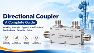
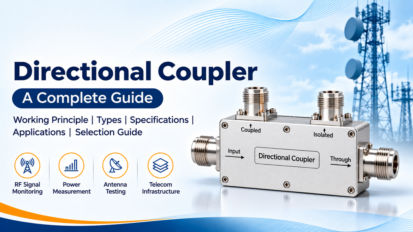
A directional coupler is a passive four-port RF device designed to transfer a specific amount of electromagnetic energy from a primary transmission line to a secondary coupled port. It allows a small portion of the input signal to be sampled while the remaining power continues through the main line.
A typical directional coupler consists of four ports:
- Input Port: Receives the incoming RF signal.
- Through Port: Allows most of the input signal to continue toward the connected equipment.
- Coupled Port: Extracts a predefined portion of the input signal.
- Isolated Port: Ideally receives very little signal from the input port under the intended operating conditions.
Directional couplers are available in different coupling values, frequency ranges, power ratings, connector configurations, and physical designs to meet specific RF system requirements.
How Does a Directional Coupler Work?
A directional coupler works through electromagnetic coupling between two transmission lines. When an RF signal travels through the primary transmission line, a controlled portion of its energy is transferred to the secondary line.
The coupling mechanism depends on the design of the component. It may use coupled transmission lines, stripline structures, microstrip circuits, coaxial arrangements, or waveguide structures.
In a typical forward-power measurement setup, the incoming signal enters the input port. Most of the signal travels through the main line and exits through the through port. A smaller portion is transferred to the coupled port, where it can be measured using an RF power meter, detector, or monitoring circuit.
A directional coupler can also be used to monitor reflected signals. By connecting the appropriate ports in a forward and reverse monitoring arrangement, engineers can measure power travelling toward and away from an antenna or other RF load.
The direction of coupling depends on the internal design and port configuration of the coupler.
Directional Coupler Port Configuration
Understanding the four-port configuration is important for correct installation and operation.
| Port | Function |
|---|---|
| Input | Receives the RF input signal |
| Through | Carries the main RF signal to the output |
| Coupled | Provides a sampled portion of the signal |
| Isolated | Ideally receives minimal input signal |
The port arrangement and signal direction should always be verified using the manufacturer’s datasheet before connecting a directional coupler to an RF system.
Important Technical Specifications of Directional Couplers
When selecting an RF directional coupler, several electrical and mechanical parameters determine its performance.
1. Frequency Range
The frequency range specifies the operating frequencies over which the directional coupler is designed to perform within its specified limits.
Directional couplers are available for different frequency applications, including:
- VHF and UHF communication systems
- Cellular and mobile communication bands
- 4G LTE and 5G infrastructure
- Wi-Fi and wireless communication
- Microwave communication systems
- Satellite communication and radar applications
The selected frequency range should cover the complete operating band of the RF system.
2. Coupling Factor
The coupling factor indicates how much power is transferred from the main transmission line to the coupled port. It is expressed in decibels (dB).
Common coupling values include:
- 3 dB
- 6 dB
- 10 dB
- 15 dB
- 20 dB
- 30 dB
For example, a 10 dB directional coupler provides approximately one-tenth of the input power at the coupled port under ideal matched conditions.
3. Insertion Loss
Insertion loss represents the reduction in signal power between the input and through ports caused by inserting the directional coupler into the transmission path.
Lower insertion loss is generally preferred because it allows more RF power to reach the connected equipment.
4. Directivity
Directivity measures the ability of a directional coupler to distinguish between signals travelling in opposite directions.
Higher directivity indicates better separation between forward and reverse signals. It is particularly important in antenna monitoring, reflected-power measurement, and VSWR monitoring applications.
5. Isolation
Isolation refers to the attenuation between the input and isolated ports. Higher isolation helps minimise unwanted signal leakage into the isolated port.
6. VSWR
Voltage Standing Wave Ratio (VSWR) indicates how well the directional coupler is impedance-matched to the RF transmission system.
A lower VSWR generally indicates better impedance matching and reduced signal reflections.
7. Impedance
Most RF directional couplers used in commercial wireless communication systems are designed for 50-ohm impedance.
The coupler impedance should match the connected cables, connectors, antennas, and RF equipment.
8. Power Handling Capacity
Power handling specifies the maximum RF power that a directional coupler can safely handle under defined operating conditions.
The required rating depends on the transmitter output power, system configuration, duty cycle, cooling conditions, and operating environment.
9. Connector Type
Directional couplers are available with different RF connector interfaces, including:
- SMA connectors
- N-type connectors
- BNC connectors
- TNC connectors
- 7/16 DIN connectors
- 4.3-10 connectors
- Custom RF interfaces
Connector selection should consider frequency, power handling, mechanical requirements, and compatibility with the existing RF infrastructure.
Types of Directional Couplers
Directional couplers are manufactured in different configurations to support specific RF and microwave applications.
1. Coaxial Directional Coupler
Coaxial directional couplers are designed for RF systems that use coaxial transmission lines. They are commonly available with SMA, N-type, and other coaxial connector interfaces.
They are used in wireless communication, antenna systems, RF testing, and signal monitoring applications.
2. Stripline Directional Coupler
Stripline directional couplers use conductive transmission lines placed between dielectric layers and ground planes.
They provide controlled electromagnetic coupling and are suitable for compact RF and microwave circuit designs.
3. Microstrip Directional Coupler
Microstrip directional couplers use closely spaced conductive traces on a dielectric substrate. They are commonly integrated into RF circuit boards and microwave modules.
These couplers are useful where compact size, lightweight construction, and PCB integration are important.
4. Waveguide Directional Coupler
Waveguide directional couplers are designed for high-frequency microwave systems that use waveguide transmission structures.
They are commonly used in radar, satellite communication, microwave measurement systems, and high-frequency applications.
5. Dual Directional Coupler
A dual directional coupler is designed to sample signals travelling in both forward and reverse directions.
It provides separate coupled outputs for monitoring forward and reflected power. This makes it particularly useful in transmitter monitoring, antenna testing, and RF protection systems.
6. Broadband Directional Coupler
Broadband directional couplers are designed to operate across a wide frequency range while maintaining specified coupling and RF performance.
They are suitable for multi-band wireless communication, laboratory testing, and broadband RF measurement systems.
7. High-Power Directional Coupler
High-power directional couplers are engineered to handle higher RF power levels while maintaining reliable signal sampling.
They are used in broadcast transmitters, high-power RF amplifiers, communication infrastructure, and industrial RF systems.
Directional Coupler vs Power Divider
Directional couplers and power dividers are both passive RF components, but they perform different functions.
A power divider splits an input signal into two or more output signals. A directional coupler extracts a predefined portion of the signal while allowing most of the power to continue through the main transmission line.
| Parameter | Directional Coupler | Power Divider |
|---|---|---|
| Main function | Samples a portion of RF power | Splits RF power into multiple outputs |
| Main output | Through port | Multiple output ports |
| Coupled output | Controlled signal sample | Divided signal |
| Directional response | Designed for directional coupling | Generally non-directional power distribution |
| Common applications | Power monitoring and measurement | Signal distribution |
| Typical configurations | Four-port device | Two-way, three-way, four-way and more |
The correct component depends on whether the application requires signal sampling or power distribution.
Applications of Directional Couplers
Directional couplers are used across various RF, microwave, and wireless communication systems.
1. Wireless Communication Systems
Directional couplers are used in wireless communication infrastructure to monitor RF signal levels and evaluate transmitter performance.
They support RF signal monitoring in cellular networks, base stations, distributed antenna systems, and wireless communication installations.
2. Base Transceiver Stations (BTS)
In BTS infrastructure, directional couplers help monitor transmitter output power and antenna feeder performance.
They can be integrated into RF monitoring arrangements to measure forward and reflected power.
3. In-Building Solutions (IBS)
Directional couplers are commonly used in distributed antenna systems and in-building wireless coverage installations.
They help distribute and monitor RF signals across different antenna branches while maintaining the required signal levels.
4. Antenna Systems
Directional couplers are useful for measuring forward and reflected power in antenna systems.
They help engineers evaluate antenna matching, detect abnormal reflections, and monitor the performance of RF transmission lines.
5. RF Testing and Measurement
In RF laboratories and test environments, directional couplers are used to sample signals without interrupting the primary transmission path.
They are compatible with suitable power meters, spectrum analysers, network analysers, and RF detectors.
6. Radar Systems
Directional couplers are used in radar systems for RF signal monitoring, transmitter measurement, and microwave signal analysis.
7. Satellite Communication
In satellite communication infrastructure, directional couplers support RF power monitoring and signal measurement across microwave transmission systems.
8. Broadcast and Transmitter Systems
Broadcast transmitters use directional couplers to monitor forward and reflected power. This helps operators assess transmission performance and identify potential antenna or feeder issues.
9. RF Amplifier Systems
Directional couplers can be used at the input or output of RF amplifiers to monitor signal levels and support feedback or protection arrangements.
How to Select the Right Directional Coupler
Selecting the correct directional coupler is essential for maintaining reliable RF system performance.
Consider the following factors before purchasing:
1. Operating Frequency: Select a coupler whose specified frequency range covers the complete operating band of your application.
2. Coupling Value: Choose the required coupling factor based on the amount of signal that needs to be sampled.
3. Power Rating: Ensure the coupler supports the maximum RF power expected in the system.
4. Impedance: Verify whether the application requires a 50-ohm or another specified impedance.
5. Directivity: Select a suitable directivity value when accurate forward and reverse power measurements are important.
6. Insertion Loss: Consider lower insertion loss where maintaining the main signal level is important.
7. Connector Interface: Check the connector type, gender, mounting arrangement, and mechanical compatibility.
8. Environmental Conditions: Consider operating temperature, humidity, vibration, enclosure requirements, and installation environment.
9. Mechanical Dimensions: Verify the product dimensions and mounting arrangement to ensure proper integration into the existing system.
10. Datasheet Verification: Review the manufacturer’s datasheet for frequency-dependent performance, coupling tolerance, VSWR, directivity, insertion loss, and power-handling specifications.
Directional Coupler Technical Specification Checklist
The following table provides a general specification checklist for evaluating directional couplers. Actual values depend on the selected model and manufacturer.
| Specification | Description |
|---|---|
| Product Type | RF Directional Coupler |
| Frequency Range | Application-dependent |
| Coupling Factor | 3 dB, 6 dB, 10 dB, 15 dB, 20 dB, 30 dB or custom |
| Impedance | Typically 50 Ohms |
| Insertion Loss | Model-dependent |
| Directivity | Model-dependent |
| Isolation | Model-dependent |
| VSWR | Model-dependent |
| Power Handling | Application-dependent |
| Connector Type | SMA, N-Type, BNC, TNC, DIN, 4.3-10 or custom |
| Body Material | Model-dependent |
| Operating Temperature | Manufacturer-dependent |
| Mounting Type | Coaxial, PCB, flange or custom |
Always consult the product datasheet for confirmed electrical and mechanical specifications before selecting a directional coupler.
Directional Coupler Installation and Best Practices
Correct installation is important for achieving the expected performance of an RF directional coupler.
- Identify the input, through, coupled, and isolated ports before installation.
- Follow the manufacturer’s port-direction diagram.
- Use compatible RF cables and connectors.
- Ensure all RF connections are properly tightened using the recommended torque.
- Maintain the specified impedance throughout the RF transmission path.
- Avoid exceeding the rated input power.
- Use properly terminated ports as specified by the manufacturer.
- Minimise unnecessary cable bends and mechanical stress.
- Verify insertion loss, VSWR, and coupling performance during system testing.
- Protect the component from moisture, dust, vibration, and excessive temperature where required.
Incorrect port connections or impedance mismatches can affect measurement accuracy and overall RF system performance.
Common Problems and Troubleshooting
High VSWR
Solution: Inspect the RF connections, verify cable compatibility, and check the termination of unused ports according to the manufacturer’s instructions.
High VSWR may result from loose connectors, damaged cables, impedance mismatches, or incorrect port termination.
Incorrect Coupled Power Reading
Incorrect readings may occur because of the wrong coupling factor, incorrect port connections, frequency-dependent coupling variation, or measurement equipment errors.
Solution: Verify the coupler specifications and port configuration. Calibrate the measurement setup and use suitable RF test equipment.
Excessive Insertion Loss
Excessive insertion loss can result from poor connections, damaged transmission lines, unsuitable components, or operation outside the specified frequency range.
Solution: Inspect the complete RF path and verify that the coupler is being operated within its rated frequency and power limits.
Poor Directivity
Poor directivity can affect the accuracy of forward and reflected power measurements.
Solution: Check the operating frequency, port termination, connector condition, and measurement setup. Confirm that the selected coupler meets the required directivity specification.
Why Choose SRFS Teleinfra for RF Directional Couplers?
SRFS Teleinfra provides RF and microwave components for wireless communication, telecom infrastructure, and specialised RF applications.
Our product portfolio covers a range of RF components, including RF cables, cable assemblies, connectors, adapters, attenuators, terminations, antennas, and power dividers.
For directional coupler requirements, selecting the correct configuration is important. Factors such as operating frequency, coupling value, power handling, impedance, directivity, and connector interface should be considered before finalising a product.
SRFS Teleinfra supports RF component requirements for communication infrastructure and engineering applications. Contact our team to discuss your application and identify a suitable RF component based on your technical requirements.
Conclusion
Directional couplers are important passive RF components used for signal sampling, power monitoring, and measurement in modern communication systems. Their ability to extract a controlled portion of RF energy while allowing most of the signal to continue through the main transmission path makes them valuable in antenna systems, BTS infrastructure, IBS installations, radar, satellite communication, and RF testing.
Understanding parameters such as coupling factor, directivity, insertion loss, isolation, VSWR, frequency range, and power handling helps engineers select the right directional coupler for their applications.
For reliable RF system performance, always select a directional coupler based on verified datasheet specifications and the actual requirements of the installation.
Frequently Asked Questions (FAQs)
1. What is a directional coupler used for?
A directional coupler is used to sample a portion of an RF signal for monitoring and measurement while allowing most of the signal to continue through the main transmission line.
2. How many ports does a directional coupler have?
A conventional directional coupler has four ports: input, through, coupled, and isolated.
3. What is the coupling factor in a directional coupler?
The coupling factor indicates the amount of RF power transferred from the main transmission line to the coupled port. It is expressed in decibels (dB).
4. What is the difference between a directional coupler and a power divider?
A directional coupler extracts a controlled sample of RF power, whereas a power divider splits the input signal into multiple output paths.
5. What is directivity in a directional coupler?
Directivity measures the ability of a directional coupler to distinguish between signals travelling in opposite directions. Higher directivity is generally preferred for accurate forward and reflected power measurements.
6. What is a dual directional coupler?
A dual directional coupler provides separate sampling paths for forward and reverse travelling signals. It is commonly used for monitoring transmitted and reflected RF power.
7. What is the typical impedance of an RF directional coupler?
Most directional couplers used in commercial RF and wireless communication systems have a characteristic impedance of 50 ohms.
8. Can a directional coupler measure reflected power?
Yes. A suitably configured directional coupler can sample reflected power travelling back from an antenna or load, allowing engineers to monitor the performance of the RF transmission system.
9. What coupling values are available in directional couplers?
Common coupling values include 3 dB, 6 dB, 10 dB, 15 dB, 20 dB, and 30 dB. Custom coupling values may also be available depending on the manufacturer.
10. How do I choose the right RF directional coupler?
Consider the operating frequency, coupling factor, power handling, impedance, insertion loss, directivity, VSWR, connector type, and environmental requirements.
11. Are directional couplers available for high-frequency applications?
Yes. Directional couplers are available for a wide range of RF and microwave frequencies. The maximum operating frequency depends on the component design and its datasheet specifications.
12. Where are directional couplers used in telecom infrastructure?
They are used in BTS installations, distributed antenna systems, IBS networks, antenna feeder systems, RF monitoring setups, and wireless communication infrastructure.