What Is a DC Block?
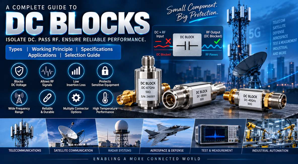
A DC Block is a passive RF and microwave component designed to prevent direct current (DC) from passing through a transmission line while allowing alternating current (AC), radio frequency (RF), and microwave signals to pass. DC Blocks are widely used in telecommunications, RF test equipment, satellite communication, radar, wireless infrastructure, aerospace, defense, and electronic measurement systems.
In high-frequency systems, unwanted DC voltage can cause serious problems when two pieces of equipment are interconnected. It can interfere with the operation of sensitive RF circuits, damage components, create measurement errors, or introduce unwanted bias into a transmission path. A DC Block provides a simple and effective method of electrically isolating the DC component while maintaining the required RF signal path.
DC Blocks are particularly important in systems where RF signals and DC voltages may exist on the same transmission line. By introducing a capacitive element into the signal path, the DC component is isolated while the desired RF signal is transmitted.
These components are available in various connector configurations, frequency ranges, impedance ratings, power levels, and mechanical formats to accommodate different RF and microwave applications.
How Does a DC Block Work?
The fundamental operating principle of a DC Block is based on the behavior of a capacitor.
A capacitor blocks steady-state DC while allowing changing electrical signals to pass. In an RF DC Block, a carefully selected capacitor or capacitive structure is incorporated into the transmission path.
When a DC voltage reaches the DC Block, the capacitor prevents the DC current from continuing through the circuit. However, when an RF signal is applied, the changing voltage allows the RF energy to pass through the capacitive element.
The effectiveness of the DC Block depends on the capacitor’s characteristics, operating frequency, capacitance, dielectric material, impedance matching, and physical construction.
At higher frequencies, the capacitive reactance becomes lower, allowing RF energy to pass with relatively low insertion loss.
This makes DC Blocks particularly useful for RF systems where DC isolation is required without significantly affecting the desired RF signal.
Why Are DC Blocks Important in RF Systems?
Modern RF systems often combine multiple components such as antennas, amplifiers, filters, attenuators, couplers, switches, signal generators, and analyzers. Some of these components may contain internal DC bias circuits or external power supplies.
Connecting such equipment without proper DC isolation can result in:
- Equipment damage
- Incorrect measurements
- Unwanted current flow
- RF circuit malfunction
- Amplifier bias problems
- Receiver overload
- Signal distortion
- Ground-loop problems
A DC Block prevents these issues by providing electrical isolation for the DC component while maintaining the RF transmission path.
Main Types of DC Blocks
DC Blocks are generally categorized according to where the DC isolation is provided and the frequency range of operation.
Inner DC Block
An Inner DC Block places the blocking capacitor in series with the center conductor of the coaxial transmission line.
This configuration blocks DC on the inner conductor while allowing the RF signal to pass.
Inner DC Blocks are commonly used in:
- RF test equipment
- Signal generators
- Spectrum analyzers
- Network analyzers
- Communication systems
- Microwave circuits
Outer DC Block
An Outer DC Block is designed to prevent DC current from flowing through the outer conductor or shield of a coaxial cable.
It provides isolation between the shields of interconnected RF equipment while maintaining the RF signal path.
Outer DC Blocks can be useful when ground isolation is required in addition to RF signal transmission.
Inner and Outer DC Block
An Inner and Outer DC Block provides DC isolation on both the center conductor and the outer conductor.
This configuration provides a higher level of electrical isolation and can be useful when complete DC isolation between two RF devices is required.
These DC Blocks are commonly selected for sensitive RF measurement systems and specialized microwave applications.
DC Block Construction
A typical RF DC Block consists of several precision components.
Center Conductor
The center conductor carries the RF signal through the component. High-conductivity materials such as copper or plated copper alloys may be used to reduce electrical losses.
Blocking Capacitor
The blocking capacitor is the most important electrical element in a DC Block.
Its primary function is to prevent DC current while allowing RF signals to pass.
The capacitor must be carefully selected to provide low insertion loss and suitable impedance characteristics across the specified frequency range.
Dielectric Material
The dielectric separates conductive elements and determines important electrical characteristics such as capacitance, dielectric loss, and frequency response.
Outer Housing
The housing provides mechanical protection and contributes to electromagnetic shielding.
Typical materials include stainless steel, brass, aluminum, and plated metal alloys.
RF Connectors
The connector interface allows the DC Block to be installed between RF components.
Common connector types include:
- SMA
- N-Type
- TNC
- BNC
- 2.92 mm
- 2.4 mm
- 1.85 mm
- 3.5 mm
- 7/16 DIN
DC Block Technical Specifications
When selecting a DC Block, engineers should evaluate several technical specifications.
| Specification | Description |
|---|---|
| Frequency Range | RF frequencies the DC Block can transmit |
| Impedance | Usually 50 Ohms or 75 Ohms |
| DC Blocking Voltage | Maximum DC voltage that can be isolated |
| Insertion Loss | RF signal loss introduced by the component |
| Return Loss | Indicates impedance matching performance |
| VSWR | Measures signal reflection |
| Power Handling | Maximum RF power supported |
| Connector Type | Interface used for RF connection |
| Isolation | Degree of DC separation |
| Operating Temperature | Permitted environmental temperature |
| Maximum Frequency | Highest specified operating frequency |
Frequency Range of DC Blocks
Frequency range is one of the most important specifications when choosing a DC Block.
Different DC Blocks are designed for different frequency ranges, such as:
- DC to 1 GHz
- 10 MHz to 3 GHz
- 10 MHz to 6 GHz
- 10 MHz to 18 GHz
- 10 MHz to 26.5 GHz
- 10 MHz to 40 GHz
- 10 MHz to 50 GHz
- 10 MHz to 67 GHz
- Millimeter-wave frequencies
A DC Block should always be selected according to the actual RF frequency range of the application.
A device designed for low-frequency RF operation may not provide acceptable insertion loss or return loss at microwave frequencies.
DC Blocking Voltage
DC blocking voltage specifies the maximum DC potential that the component can safely isolate.
For example, a DC Block may be rated for:
- 16 V
- 25 V
- 50 V
- 100 V
- 250 V
- 500 V
The required rating depends on the voltage present in the RF system.
The DC blocking voltage should never be exceeded because excessive voltage can damage the internal capacitor and compromise the isolation performance.
RF Power Handling
Although a DC Block is primarily used for DC isolation, it must also be capable of handling the RF power transmitted through it.
Power handling depends on:
- Frequency
- Connector design
- Internal construction
- Dielectric material
- Thermal management
- Ambient temperature
- DC voltage
High-power applications require DC Blocks specifically designed for elevated RF power levels.
Impedance of DC Blocks
The most common RF impedance values are 50 Ohms and 75 Ohms.
50 Ohm DC Blocks
50 Ohm DC Blocks are widely used in:
- Wireless communication
- Cellular infrastructure
- 5G systems
- Radar
- Aerospace
- Defense
- RF laboratories
- Microwave systems
75 Ohm DC Blocks
75 Ohm DC Blocks are commonly associated with:
- Cable television
- Video transmission
- Broadcast systems
- Broadband networks
- Television distribution
Using the correct impedance is essential for minimizing signal reflections and maintaining system performance.
DC Block Applications
DC Blocks are used across a wide range of RF and microwave applications.
RF Test and Measurement
DC Blocks are commonly used with:
- Spectrum analyzers
- Vector network analyzers
- Signal generators
- Power meters
- Oscilloscopes
- RF receivers
They prevent unwanted DC voltage from reaching sensitive measurement equipment.
Telecommunications
Telecommunication systems use DC Blocks for signal isolation and protection between RF components.
Applications include:
- Cellular base stations
- RF repeaters
- Distributed antenna systems
- 5G infrastructure
- Wireless communication equipment
Satellite Communication
Satellite systems often require precise RF signal routing and DC isolation.
DC Blocks can be used in:
- Satellite receivers
- Ground stations
- VSAT systems
- RF distribution networks
- Satellite test equipment
Radar Systems
Radar equipment operates at high frequencies and can contain sensitive RF front-end circuits.
DC Blocks help isolate unwanted DC components between:
- Antennas
- Amplifiers
- Filters
- Receivers
- Test equipment
Aerospace and Defense
Aerospace and defense systems require reliable RF signal management.
DC Blocks are used in:
- Radar
- Electronic warfare systems
- Military communication
- Avionics
- RF test systems
- Microwave equipment
5G and Wireless Infrastructure
The increasing complexity of 5G RF architectures has increased the importance of precise signal isolation.
DC Blocks can be used in:
- RF front-end modules
- Antenna systems
- Small cells
- Base stations
- RF testing systems
- Distributed antenna systems
DC Block in RF Testing
DC Blocks are especially important in RF test laboratories.
Many RF instruments have maximum allowable DC input levels. If an external RF device accidentally introduces DC voltage into the instrument, the input circuitry can potentially be damaged.
A DC Block installed between the device under test and the measurement instrument provides an additional layer of protection.
For example, an engineer testing an RF amplifier may place a DC Block between the amplifier output and a spectrum analyzer to prevent unwanted DC voltage from entering the analyzer.
DC Block vs Bias Tee
DC Blocks and bias tees are related but perform opposite functions.
A DC Block prevents DC from passing through an RF path.
A bias tee combines DC power and RF signals onto the same transmission line.
| Feature | DC Block | Bias Tee |
|---|---|---|
| DC Function | Blocks DC | Injects or separates DC |
| RF Transmission | Allows RF | Allows RF |
| Primary Purpose | DC isolation | DC + RF combination |
| Common Use | Equipment protection | Amplifier/active antenna biasing |
| External Power | Not required | Usually required |
| Typical Application | RF testing | Active RF devices |
DC Block vs DC Pass
A DC Block and DC Pass serve opposite functions.
A DC Block prevents DC from traveling through the transmission path.
A DC Pass allows DC voltage to travel along with the RF signal.
| Feature | DC Block | DC Pass |
|---|---|---|
| DC Transmission | No | Yes |
| RF Transmission | Yes | Yes |
| Primary Function | DC isolation | DC power delivery |
| Common Application | Protection | Biasing active devices |
Benefits of Using DC Blocks
DC Blocks provide several important advantages.
Equipment Protection
They prevent unwanted DC voltage from reaching sensitive RF equipment.
Electrical Isolation
They provide isolation between interconnected RF circuits.
RF Signal Transmission
A properly designed DC Block allows the desired RF signal to pass with minimal degradation.
Reduced Measurement Errors
They help prevent DC components from affecting RF measurement instruments.
Improved System Reliability
By isolating unwanted DC voltages, DC Blocks can reduce the risk of component failure.
Compact Installation
Many DC Blocks are designed as small inline adapters that can be installed directly between RF connectors.
Important DC Block Performance Parameters
Insertion Loss
Insertion loss indicates how much RF signal power is lost when the DC Block is inserted into the signal path.
Lower insertion loss is generally preferred.
Return Loss
Return loss indicates how well the DC Block matches the characteristic impedance of the RF system.
Higher return loss generally indicates better impedance matching.
VSWR
Voltage Standing Wave Ratio measures the degree of signal reflection caused by impedance mismatch.
A lower VSWR indicates better RF performance.
Isolation
Isolation specifies how effectively the DC component is prevented from crossing the blocking element.
Phase Performance
In precision RF systems, the phase response of the DC Block may be important, particularly in applications involving phase-sensitive measurements.
How to Choose the Right DC Block
Choosing the correct DC Block requires careful evaluation of the system requirements.
1. Determine the Frequency Range
Select a DC Block whose specified frequency range covers the complete operating band of the application.
2. Check the Impedance
Confirm whether the system requires 50 Ohm or 75 Ohm impedance.
3. Verify DC Voltage
Make sure the DC blocking voltage rating is higher than the maximum voltage that could occur in the system.
4. Check RF Power
Verify that the DC Block can handle the maximum RF power.
5. Select the Correct Connector
Choose the connector according to the equipment being connected.
6. Review VSWR and Return Loss
For high-frequency applications, good VSWR and return loss are essential.
7. Consider Environmental Conditions
For outdoor, aerospace, or industrial applications, consider temperature, humidity, vibration, corrosion, and mechanical requirements.
Common Connector Types for DC Blocks
SMA DC Block
SMA DC Blocks are commonly used for compact RF and microwave applications.
N-Type DC Block
N-Type DC Blocks are suitable for applications requiring robust mechanical construction and higher power handling.
BNC DC Block
BNC versions are widely used in laboratory and test equipment.
TNC DC Block
TNC DC Blocks provide a threaded RF connection suitable for applications exposed to vibration.
2.92 mm DC Block
2.92 mm DC Blocks are designed for high-frequency microwave and millimeter-wave applications.
2.4 mm and 1.85 mm DC Blocks
These precision connectors are used in very high-frequency applications where excellent RF performance is required.
Installation Best Practices
Correct installation is essential for maintaining DC Block performance.
- Verify connector compatibility before installation.
- Confirm the impedance of both connected devices.
- Check the DC voltage before connecting equipment.
- Do not exceed the rated DC blocking voltage.
- Do not exceed the specified RF power.
- Keep RF connectors clean.
- Avoid excessive mechanical force.
- Use appropriate connector torque.
- Avoid unnecessary cable movement.
- Inspect the DC Block for physical damage before use.
Common Mistakes When Using DC Blocks
Several installation mistakes can reduce performance.
Using the Wrong Frequency Rating
A DC Block designed for a lower frequency range may perform poorly at higher frequencies.
Exceeding the Voltage Rating
Excessive DC voltage can damage the internal blocking capacitor.
Ignoring RF Power
High RF power can cause excessive heating and component failure.
Using the Wrong Impedance
Connecting a 50 Ohm DC Block to a 75 Ohm system can introduce impedance mismatch.
Selecting the Wrong Connector
Connector incompatibility can cause poor mechanical and electrical connections.
DC Blocks in Modern RF Systems
The growth of wireless communication and high-frequency electronics has increased the demand for precision DC Blocks.
Modern applications increasingly operate at higher frequencies, making low insertion loss, excellent return loss, stable impedance, and reliable DC isolation more important than ever.
5G infrastructure, satellite internet, advanced radar, aerospace electronics, semiconductor testing, and emerging millimeter-wave technologies all require high-performance RF components capable of maintaining signal integrity.
DC Blocks remain a relatively simple component, but their role in protecting equipment and controlling signal paths makes them highly valuable in modern RF engineering.
Future of DC Block Technology
Future DC Block designs are expected to support wider frequency ranges, higher RF power, improved electrical isolation, lower insertion loss, and more compact mechanical designs.
As RF systems move toward millimeter-wave and higher-frequency operation, manufacturers are developing precision DC Blocks with advanced dielectric materials, improved connector interfaces, better thermal performance, and optimized microwave structures.
The expansion of 5G, 6G research, satellite communication, autonomous vehicles, radar, aerospace electronics, and high-speed wireless systems will continue creating demand for high-frequency DC isolation solutions.
Conclusion
DC Blocks are essential passive RF components used to prevent unwanted DC voltage from passing through an RF transmission path while allowing the desired RF and microwave signals to continue with minimal disruption. Their ability to provide DC isolation makes them valuable for protecting sensitive equipment, improving measurement reliability, isolating RF circuits, and maintaining safe system operation.
From telecommunications and 5G infrastructure to satellite communication, radar, aerospace, defense, medical electronics, and laboratory testing, DC Blocks are used across a wide range of applications.
When selecting a DC Block, engineers should carefully evaluate frequency range, impedance, DC blocking voltage, RF power handling, insertion loss, return loss, VSWR, connector type, and environmental requirements. Choosing the correct component ensures reliable RF transmission, effective DC isolation, and long-term system performance.
Frequently Asked Questions About DC Blocks
1. What is a DC Block?
A DC Block is a passive RF component that prevents direct current from passing through a transmission line while allowing RF and microwave signals to pass.
2. What is the main purpose of a DC Block?
The main purpose is to provide DC isolation between RF components while maintaining the transmission of the desired RF signal.
3. How does a DC Block work?
A DC Block generally uses a capacitive element in series with the RF signal path. The capacitor blocks steady-state DC while allowing changing RF signals to pass.
4. Where are DC Blocks used?
DC Blocks are used in RF test equipment, telecommunications, 5G systems, satellite communication, radar, aerospace, defense, wireless infrastructure, and laboratory applications.
5. Does a DC Block stop RF signals?
No. A properly designed DC Block allows RF signals within its specified frequency range to pass while blocking DC voltage.
6. What is the difference between a DC Block and a bias tee?
A DC Block prevents DC from passing through an RF path, whereas a bias tee combines DC power with an RF signal or separates the two.
7. What impedance is commonly used for RF DC Blocks?
Most RF DC Blocks are designed for 50 Ohm systems. 75 Ohm versions are also available for applications such as cable television and video distribution.
8. Can a DC Block protect a spectrum analyzer?
Yes. When correctly selected and installed, a DC Block can prevent unwanted DC voltage from reaching the sensitive RF input of a spectrum analyzer.
9. What is DC blocking voltage?
DC blocking voltage is the maximum DC voltage that a DC Block is designed to withstand without electrical breakdown or damage.
10. What connectors are available for DC Blocks?
DC Blocks are available with SMA, N-Type, BNC, TNC, 2.92 mm, 2.4 mm, 1.85 mm, 3.5 mm, and other RF connector interfaces.
11. Can DC Blocks be used at microwave frequencies?
Yes. Specialized DC Blocks are designed for microwave and millimeter-wave frequencies, including applications extending into tens of gigahertz and beyond.
12. How do I select a DC Block?
Select a DC Block according to operating frequency, impedance, DC blocking voltage, RF power, insertion loss, VSWR, return loss, connector type, and environmental requirements.
For top-notch RF & 5G components solutions, choose SRFS TELEINFRA. Get in touch: Call Us: 7838349349 Or Email Us: info@srfsteleinfra.in