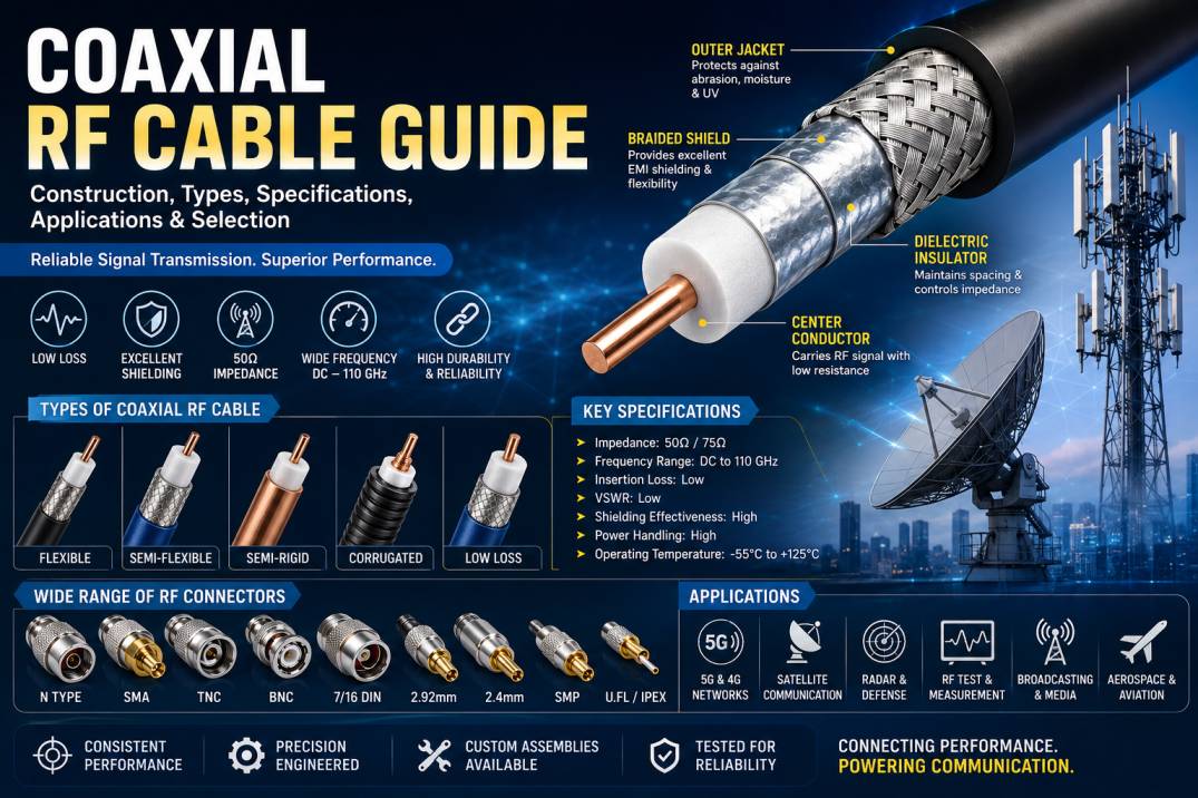
Coaxial RF cable is one of the most widely used transmission-line technologies for carrying radio frequency signals between antennas, transmitters, receivers, amplifiers, filters, test equipment, and communication systems. From 4G and 5G infrastructure to satellite communication, radar, aerospace, defense, broadcasting, wireless networks, and RF laboratories, coaxial cables provide a controlled path for transmitting high-frequency electrical signals.
Unlike ordinary electrical wires, coaxial RF cables are specifically engineered to maintain controlled impedance, minimize signal loss, reduce electromagnetic interference, and provide predictable performance over a defined frequency range.
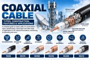
The construction of a coaxial RF cable consists of a center conductor, dielectric insulation, outer conductor or shield, and protective jacket. The dimensions and materials of these layers determine important characteristics such as impedance, attenuation, VSWR, return loss, shielding effectiveness, power handling, flexibility, and phase stability.
This comprehensive coaxial RF cable guide explains how coaxial cables work, their construction, major cable types, specifications, applications, advantages, limitations, installation practices, testing methods, and how to select the right cable for an RF system.
What Is a Coaxial RF Cable?
A coaxial RF cable is a transmission cable designed to carry radio frequency signals using two conductors arranged along the same axis.
The inner conductor carries the RF signal, while the surrounding outer conductor provides the return path and electromagnetic shielding. A dielectric material separates the two conductors and maintains the required geometry.
The basic coaxial RF cable structure consists of:
Center conductor
Dielectric insulator
Outer conductor or shield
Protective jacket
The concentric arrangement allows coaxial cables to provide controlled impedance and excellent electromagnetic shielding compared with many other types of electrical transmission lines.
How Does a Coaxial RF Cable Work?
A coaxial cable transmits an RF signal through the electromagnetic field established between the center conductor and outer conductor.
The center conductor carries the forward signal, while the outer conductor acts as the return path. The dielectric material between them controls the electromagnetic field distribution.
Because the electromagnetic field is largely contained within the cable structure, coaxial cables can provide good resistance to external electromagnetic interference and reduce signal radiation.
The cable must maintain consistent dimensions along its entire length. Any significant change in conductor diameter, dielectric thickness, connector geometry, or shielding structure can introduce an impedance discontinuity and cause signal reflections.
Construction of a Coaxial RF Cable
Understanding coaxial cable construction is essential when selecting a cable for RF applications.
Center Conductor
The center conductor is the primary signal-carrying element.
Common conductor materials include:
Copper
Silver-plated copper
Copper-clad steel
Tin-plated copper
Specialized conductive alloys
Copper is widely used because of its high electrical conductivity. Silver-plated copper may be used in high-performance applications because of its excellent surface conductivity and corrosion resistance.
The conductor can be solid, stranded, or specially constructed depending on the required flexibility and RF performance.
Solid Center Conductor
A solid center conductor consists of a single continuous metal conductor.
It provides excellent dimensional stability, low resistance, and predictable RF characteristics.
Solid conductors are commonly used in semi-rigid, semi-flexible, and high-performance coaxial cables.
Stranded Center Conductor
A stranded conductor consists of multiple small wires.
This construction increases flexibility and makes the cable easier to route through equipment and installations.
Flexible RF cables frequently use stranded center conductors where mechanical movement is important.
Dielectric Insulator
The dielectric is positioned between the center conductor and outer conductor.
It performs several important functions:
Electrical isolation
Mechanical support
Impedance control
Signal propagation control
Protection of the center conductor
Common dielectric materials include PTFE, polyethylene, FEP, foam polyethylene, and specialized low-loss materials.
PTFE Dielectric
PTFE is widely used in high-performance RF and microwave cables because it provides low dielectric loss, excellent temperature stability, chemical resistance, and good electrical characteristics.
PTFE-based coaxial cables are frequently used in aerospace, defense, microwave, laboratory, and high-frequency test applications.
Foamed Dielectric
Foamed dielectric materials contain air-filled cells that reduce the effective dielectric constant.
This can help reduce dielectric losses and improve propagation velocity.
Foamed dielectric construction is commonly used in low-loss telecom and wireless infrastructure cables.
Outer Conductor and Shield
The outer conductor surrounds the dielectric and serves two major purposes.
First, it provides the return path for the RF signal.
Second, it shields the internal signal from external electromagnetic interference.
Depending on the cable design, the outer conductor may consist of:
Braided copper
Tinned copper braid
Aluminum foil
Copper foil
Solid copper tube
Corrugated metal
Multiple layers of foil and braid
Braided Coaxial RF Cable
Braided coaxial cables use woven conductive wires around the dielectric.
The braid provides flexibility while offering electromagnetic shielding.
Some cables use a single braid, while higher-performance cables may use dual or multiple shielding layers.
Braided coaxial RF cables are commonly used in:
RF test equipment
Communication equipment
Wireless devices
Instrumentation
Broadcasting systems
Laboratory equipment
Foil Shielded Coaxial Cable
Foil shielding uses a thin conductive foil around the dielectric.
Foil provides excellent coverage and can improve shielding effectiveness across a broad frequency range.
A foil shield is often combined with a braid to provide both high shielding and mechanical flexibility.
Double-Shielded Coaxial RF Cable
Double-shielded coaxial cables use two conductive shielding layers.
A common construction may include a foil layer followed by a braided shield.
This construction provides improved isolation and is useful where electromagnetic interference is a major concern.
Solid Shielded Coaxial Cable
A solid metallic outer conductor provides extremely effective shielding and strong mechanical protection.
Semi-rigid RF cables commonly use this construction.
The primary advantage is excellent electrical isolation and dimensional stability. The main limitation is reduced flexibility.
Protective Jacket
The outer jacket protects the internal cable construction from the surrounding environment.
Common jacket materials include:
PVC
PE
FEP
PUR
Specialized fluoropolymers
The jacket may provide resistance to UV radiation, moisture, abrasion, chemicals, temperature variations, and mechanical damage.
Outdoor coaxial RF cables require particularly durable jackets because they may be exposed to rain, sunlight, wind, temperature cycling, and physical stress.
Characteristic Impedance of Coaxial RF Cable
Characteristic impedance is one of the most important specifications of an RF coaxial cable.
The most common impedance values are 50 Ohm and 75 Ohm.
50 Ohm Coaxial Cable
50 Ohm coaxial cables are widely used in RF and microwave systems.
Typical applications include:
5G infrastructure
4G systems
RF testing
Wireless communication
Radar
Satellite communication
Aerospace
Defense
Industrial RF systems
Antennas
75 Ohm Coaxial Cable
75 Ohm coaxial cables are commonly used in:
Television
Video distribution
Broadcasting
CCTV
Cable television
Video transmission
The correct impedance must match the connected RF equipment to minimize reflections.
Coaxial Cable Impedance and Geometry
The characteristic impedance of a coaxial cable is strongly related to the ratio between the center conductor diameter and inner diameter of the outer conductor, as well as the dielectric constant of the insulating material.
This means that even small changes in cable geometry can affect impedance.
Manufacturers must therefore carefully control:
Center conductor diameter
Dielectric diameter
Outer conductor dimensions
Concentricity
Dielectric constant
Connector dimensions
Maintaining consistent geometry is particularly important at microwave and millimeter-wave frequencies.
RF Cable Attenuation
Attenuation describes the reduction in RF signal power as it travels through the cable.
It is usually specified in dB per unit length.
Attenuation depends on:
Operating frequency
Cable length
Conductor resistance
Dielectric losses
Cable diameter
Shield construction
Temperature
Material selection
Generally, larger-diameter coaxial cables can provide lower attenuation than smaller cables because they can use larger conductors and lower-loss construction.
Insertion Loss
Insertion loss represents the signal power lost when a cable or component is inserted into an RF transmission path.
A low insertion-loss coaxial cable is important when the RF signal must travel over significant distances.
High insertion loss can reduce:
Received signal strength
System range
Link budget
Receiver sensitivity
Overall network efficiency
For long RF transmission paths, low-loss coaxial cables are often preferred.
VSWR in Coaxial RF Cables
Voltage Standing Wave Ratio, or VSWR, indicates the degree of impedance mismatch in an RF transmission system.
A properly constructed coaxial RF cable with appropriate connectors should have low VSWR over its specified frequency range.
High VSWR can indicate impedance mismatch caused by:
Poor cable construction
Damaged dielectric
Incorrect connectors
Poor termination
Connector damage
Cable deformation
Incorrect installation
Low VSWR is particularly important in high-frequency RF systems and precision test applications.
Return Loss
Return loss measures the amount of RF energy reflected toward the source because of impedance mismatch.
A higher return loss generally indicates lower reflected power and better impedance matching.
Cable assemblies used in precision RF applications should therefore be designed with appropriate impedance control and high-quality connector termination.
Shielding Effectiveness
Shielding effectiveness describes how effectively a coaxial cable prevents electromagnetic energy from entering or escaping the cable.
High shielding effectiveness is important in environments containing:
High-power transmitters
Radar systems
Multiple antennas
RF laboratories
Dense 5G networks
Defense equipment
Industrial electronics
Sensitive measurement systems
Multi-layer shielding can significantly improve isolation.
Power Handling of Coaxial RF Cable
Power handling refers to the maximum RF power a cable can transmit under specified operating conditions.
Power capacity depends on:
Cable diameter
Frequency
Dielectric material
Conductor size
Ambient temperature
Cable length
VSWR
Cooling conditions
Dielectric breakdown characteristics
Larger coaxial cables generally support higher power levels, while miniature coaxial cables are typically intended for lower-power signal transmission.
Frequency Range of Coaxial RF Cable
Every coaxial RF cable has a specified frequency range.
Common cable categories may cover applications from low-frequency RF through microwave and millimeter-wave frequencies.
The usable frequency range depends on:
Cable geometry
Dielectric material
Conductor construction
Shield design
Connector interface
Manufacturing precision
At very high frequencies, connector performance and dimensional tolerances become increasingly important.
Flexible Coaxial RF Cable
Flexible coaxial RF cables are designed to bend easily.
They are commonly used where cables need to be routed around equipment or experience some degree of movement.
Advantages include:
Easy installation
High flexibility
Simple routing
Good mechanical handling
Wide range of connector options
Flexible coaxial cables are commonly found in RF equipment, antennas, wireless devices, instrumentation, and test systems.
Semi-Flexible Coaxial RF Cable
Semi-flexible coaxial cables provide a balance between flexibility and high-frequency performance.
They are generally more stable than highly flexible cables while still allowing controlled bending during installation.
They are useful for:
RF modules
Microwave equipment
Test systems
Aerospace equipment
Defense electronics
Communication systems
Semi-Rigid Coaxial RF Cable
Semi-rigid coaxial cables use a solid outer metallic conductor.
They provide:
Excellent shielding
Low RF leakage
Stable impedance
High-frequency performance
Good mechanical protection
Excellent phase stability
Semi-rigid cables are widely used in microwave assemblies, laboratory instruments, aerospace electronics, defense systems, and precision RF equipment.
Corrugated Coaxial RF Cable
Corrugated coaxial cables are widely used as RF feeder cables in telecom infrastructure.
The corrugated outer conductor allows the cable to flex while maintaining strong shielding.
They are commonly used between radio equipment and antennas.
Typical applications include:
Cellular base stations
4G networks
5G networks
Distributed antenna systems
Outdoor wireless infrastructure
Telecom towers
Low-Loss Coaxial RF Cable
Low-loss coaxial RF cables are engineered to minimize attenuation.
They may use:
Low-loss dielectric materials
Large conductors
Optimized shielding
Low-resistance conductors
Specialized foam dielectric
Low-loss cables are especially useful for long RF transmission paths where every decibel of signal loss matters.
Phase-Stable Coaxial RF Cable
Phase-stable cables are designed to maintain predictable electrical phase when exposed to mechanical movement and temperature variations.
They are important for applications where phase accuracy is critical.
Examples include:
Vector network analyzers
Phased-array radar
Satellite communication
Aerospace testing
RF calibration
5G measurement systems
Precision microwave systems
High-Frequency Coaxial RF Cable
High-frequency coaxial cables are designed for microwave and millimeter-wave applications.
They require highly precise manufacturing because small mechanical changes can significantly affect electrical performance.
High-frequency cable assemblies may use connectors such as:
SMA
2.92mm
2.4mm
1.85mm
SMP
SMPM
These cables are commonly used in advanced test, measurement, aerospace, defense, radar, and communication systems.
Coaxial RF Cable Connectors
The connector is a critical part of a coaxial RF cable assembly.
Common RF connectors include:
N-Type Connector
SMA Connector
TNC Connector
BNC Connector
QMA Connector
7/16 DIN Connector
4.3/10 Connector
SMB Connector
MCX Connector
MMCX Connector
2.92mm Connector
2.4mm Connector
1.85mm Connector
SMP Connector
SMPM Connector
U.FL/IPEX Connector
Connector selection depends on frequency, impedance, mechanical interface, power level, environmental requirements, and application.
RF Cable Assembly
A coaxial RF cable assembly consists of a coaxial cable terminated with connectors on one or both ends.
Examples include:
SMA to SMA cable assembly
N-Type to N-Type cable assembly
N-Type to SMA cable assembly
SMA to 2.92mm cable assembly
SMP to SMPM cable assembly
SMA to U.FL cable assembly
The cable length, connector orientation, connector gender, cable type, and electrical specifications can be customized according to system requirements.
Coaxial RF Cable Applications
Coaxial RF cables are used across a wide range of industries.
Telecommunications
Coaxial RF cables are used for antenna feeder connections, radio equipment, base stations, repeaters, and wireless infrastructure.
5G Networks
5G infrastructure requires high-performance RF cables for antenna systems, radio units, testing equipment, and distributed network architectures.
Aerospace
Aerospace systems require lightweight, reliable, temperature-resistant, and phase-stable RF cable assemblies.
Defense
Defense applications include radar, electronic warfare systems, secure communication, RF testing, and surveillance systems.
Satellite Communication
Coaxial RF cables are used within satellite ground stations, RF equipment, antenna systems, and communication subsystems.
Radar
Radar systems depend on low-loss and phase-stable RF cable assemblies for transmitting and receiving high-frequency signals.
Broadcasting
Coaxial cables are widely used in radio, television, video, and broadcast transmission systems.
RF Test and Measurement
Test laboratories use precision coaxial cable assemblies with high-quality connectors for network analyzers, signal generators, spectrum analyzers, power meters, and other RF instruments.
Industrial Applications
Industrial RF cables may be used in sensors, automation equipment, heating systems, wireless communication systems, and instrumentation.
Advantages of Coaxial RF Cable
Coaxial RF cables offer several important advantages.
Controlled Impedance
Coaxial geometry allows manufacturers to produce cables with stable and predictable impedance.
Excellent Shielding
The outer conductor provides protection against electromagnetic interference.
Wide Frequency Capability
Coaxial cables are available for applications ranging from lower RF frequencies through microwave and millimeter-wave frequencies.
Mechanical Reliability
Properly constructed coaxial cables can withstand bending, vibration, environmental exposure, and mechanical handling depending on their design.
Wide Connector Compatibility
A large variety of RF connectors can be attached to coaxial cables.
Easy Installation
Flexible coaxial cables can be routed through equipment and telecom installations relatively easily.
Limitations of Coaxial RF Cables
Despite their advantages, coaxial cables also have limitations.
Signal Loss
Long cables can introduce significant attenuation, particularly at high frequencies.
Size and Weight
Large low-loss coaxial cables can be heavier and more difficult to install.
Bending Restrictions
Semi-rigid and certain high-performance cables have strict minimum bend-radius requirements.
Connector Loss
The connector interface can introduce additional insertion loss and reflections.
Frequency Limitations
Every cable and connector has a maximum recommended operating frequency.
Coaxial RF Cable Selection Guide
Selecting the correct coaxial RF cable requires consideration of the entire RF system.
Determine the Frequency
First identify the lowest and highest operating frequencies.
Select the Correct Impedance
Determine whether the equipment requires 50 Ohm or 75 Ohm impedance.
Check Cable Length
Estimate the required cable length and calculate the expected attenuation.
Evaluate Insertion Loss
Choose a cable with sufficiently low attenuation for the system link budget.
Check VSWR
For high-frequency and precision applications, select cable assemblies with suitable VSWR performance.
Consider Power
Verify that the cable can safely handle the maximum RF power.
Check Environmental Conditions
Outdoor installations may require UV-resistant, waterproof, corrosion-resistant, and weatherproof cable construction.
Select the Correct Connector
Connector type, gender, interface, frequency rating, and mounting configuration must match the equipment.
Consider Flexibility
Choose flexible, semi-flexible, semi-rigid, or corrugated cable according to installation requirements.
Consider Phase Stability
For precision measurement, radar, phased-array, and aerospace systems, phase-stable cable construction may be required.
Coaxial RF Cable Installation Best Practices
Correct installation is essential for maintaining cable performance.
Avoid exceeding the manufacturer’s minimum bend radius.
Do not sharply kink the cable.
Avoid crushing or flattening the cable.
Use the recommended connector torque.
Keep connectors clean.
Protect outdoor connections against moisture.
Avoid unnecessary cable length.
Use proper cable support and routing.
Prevent excessive mechanical tension.
Do not repeatedly bend cables that are not designed for dynamic movement.
Inspect cable assemblies before installation.
Improper installation can significantly affect VSWR, insertion loss, shielding, and service life.
Coaxial RF Cable Testing
Professional RF cable assemblies can be tested using RF test equipment such as vector network analyzers.
Important parameters include:
Insertion loss
Return loss
VSWR
Impedance
Phase
Continuity
Shielding effectiveness
Connector integrity
Environmental performance where required
Testing allows manufacturers and system integrators to verify that cable assemblies meet the required electrical specifications.
Common Coaxial RF Cable Problems
Several issues can reduce coaxial cable performance.
Damaged Dielectric
Crushing or excessive bending can deform the dielectric and change the cable impedance.
Connector Damage
Damaged connector interfaces can create significant signal reflections.
Moisture Ingress
Water entering an outdoor cable assembly can increase attenuation and cause corrosion.
Excessive Bending
Sharp bends can permanently deform the cable and affect its electrical characteristics.
Poor Termination
Incorrect connector installation can lead to high VSWR and increased insertion loss.
Incorrect Cable Selection
Using a cable outside its specified frequency, power, or environmental range can cause poor performance or premature failure.
Coaxial Cable Maintenance
Regular inspection can extend the operating life of RF cable assemblies.
Inspect connectors for corrosion or mechanical damage.
Check cable jackets for cracks.
Inspect cable routing for excessive bending.
Verify that outdoor connections remain weatherproof.
Check for signs of crushing or deformation.
Perform RF measurements when system performance changes unexpectedly.
Replacing damaged cable assemblies can prevent larger system-level problems.
Coaxial RF Cable for 4G and 5G Infrastructure
Modern wireless infrastructure requires reliable RF transmission between radios and antennas.
Coaxial RF cables may be used in:
Base stations
Remote radio units
Small cells
Distributed antenna systems
Repeater systems
Indoor coverage systems
5G test platforms
Antenna feeder systems
Low-loss and high-performance cable designs can help reduce transmission losses and maintain the required RF link budget.
Coaxial RF Cable for RF Testing
Precision RF test cables are designed for repeatable measurements.
A test cable may require:
Low insertion loss
Low VSWR
High shielding effectiveness
Phase stability
Precision connectors
High mechanical durability
Repeatable performance
Such cable assemblies are particularly important for vector network analyzers and microwave test systems.
Coaxial RF Cable Manufacturing Quality
Manufacturing quality has a direct impact on RF performance.
Important manufacturing controls include:
Conductor dimensional accuracy
Dielectric concentricity
Shield coverage
Jacket thickness
Connector machining
Connector termination
Impedance control
Electrical testing
Mechanical inspection
Environmental testing
High-frequency coaxial cable assemblies require particularly precise manufacturing because dimensional errors become increasingly significant as frequency increases.
Why Choose High-Quality Coaxial RF Cable?
A high-quality coaxial RF cable provides predictable electrical performance and mechanical reliability.
The right cable can help reduce:
Signal attenuation
Impedance mismatch
RF reflections
Electromagnetic interference
Measurement errors
System downtime
Maintenance requirements
Choosing cable based solely on price can lead to higher long-term costs if poor performance results in signal degradation or premature failure.
SRFS Teleinfra Coaxial RF Cable Solutions
SRFS Teleinfra provides RF and telecom infrastructure solutions for wireless communication, RF systems, telecom networks, testing, and related applications.
The RF product range can include coaxial RF cables, RF cable assemblies, connectors, adapters, clamps, weatherproofing products, and other telecom accessories.
Coaxial RF cable assemblies can be configured according to application requirements such as cable type, impedance, frequency range, connector combination, cable length, and environmental conditions.
For telecom, 4G, 5G, RF testing, aerospace, defense, industrial, and wireless communication applications, selecting the correct coaxial RF cable is essential for achieving reliable signal transmission.
Future of Coaxial RF Cable Technology
The continued development of 5G, satellite communication, advanced radar, aerospace systems, high-frequency testing, and emerging 6G technologies is increasing demand for high-performance coaxial cables.
Future RF cable development is expected to focus on:
Higher frequency operation
Lower attenuation
Improved phase stability
Better shielding
Smaller cable dimensions
Lightweight construction
Higher power density
Improved thermal performance
More reliable high-frequency connectors
Precision manufacturing
As RF frequencies continue to increase, cable and connector design will become even more important to maintaining signal integrity.
Conclusion
A coaxial RF cable is a carefully engineered transmission system rather than simply a wire surrounded by insulation. Its center conductor, dielectric, outer conductor, shielding, jacket, and connectors work together to control RF signal transmission.
The most important specifications to consider when selecting a coaxial RF cable include frequency range, impedance, attenuation, insertion loss, VSWR, return loss, shielding effectiveness, power handling, flexibility, temperature range, environmental resistance, and connector type.
From 4G and 5G networks to radar, satellite communication, aerospace, defense, broadcasting, industrial systems, and RF test laboratories, coaxial RF cables remain a fundamental part of modern communication infrastructure.
Selecting the appropriate coaxial RF cable and installing it correctly can significantly improve signal integrity, system reliability, and overall RF performance.
Frequently Asked Questions About Coaxial RF Cable
What is a coaxial RF cable?
A coaxial RF cable is a transmission cable designed to carry radio frequency signals using a center conductor, dielectric insulation, and surrounding outer conductor arranged concentrically.
What are the main parts of a coaxial RF cable?
The main parts are the center conductor, dielectric insulator, outer conductor or shield, and protective jacket. An RF cable assembly also includes connectors.
What is the difference between 50 Ohm and 75 Ohm coaxial cable?
50 Ohm coaxial cable is widely used for RF, wireless, microwave, telecom, radar, aerospace, and test applications. 75 Ohm cable is commonly used for television, video, broadcasting, and related systems.
What is the purpose of the dielectric in coaxial cable?
The dielectric separates the center conductor from the outer conductor while providing mechanical support and controlling the cable’s electrical characteristics and impedance.
Why is shielding important in coaxial RF cable?
Shielding helps prevent electromagnetic interference from entering the cable and reduces RF energy escaping from the cable.
What is coaxial cable attenuation?
Attenuation is the reduction in RF signal power as the signal travels through the cable. It is normally specified in dB per unit length.
What is a low-loss coaxial RF cable?
A low-loss coaxial RF cable is designed to minimize signal attenuation using optimized conductor materials, dielectric construction, cable dimensions, and shielding.
What is VSWR in coaxial cable?
VSWR, or Voltage Standing Wave Ratio, indicates the degree of impedance mismatch and signal reflection in an RF transmission system. Lower VSWR generally represents better impedance matching.
Which coaxial cable is best for 5G?
The appropriate cable depends on the frequency, distance, power, connector type, installation environment, and performance requirements. Low-loss and high-frequency coaxial cables are commonly selected for demanding 5G applications.
What is the difference between flexible and semi-rigid coaxial cable?
Flexible coaxial cable is designed for easier bending and routing, while semi-rigid coaxial cable uses a solid metallic outer conductor for excellent shielding and dimensional stability.
What is a phase-stable coaxial cable?
A phase-stable coaxial cable is designed to minimize changes in electrical phase caused by temperature variations and mechanical movement.
Can coaxial RF cable be used outdoors?
Yes. Outdoor-rated coaxial RF cables can be used for telecom and antenna applications when their jacket, shielding, connectors, and environmental protection are designed for outdoor conditions.
How does cable length affect RF signal performance?
Longer cable lengths generally result in greater signal attenuation. At higher frequencies, the effect of cable length can become particularly significant.
What connectors are commonly used with coaxial RF cables?
Common connectors include SMA, N-Type, TNC, BNC, QMA, 7/16 DIN, 4.3/10, 2.92mm, 2.4mm, 1.85mm, SMP, SMPM, MCX, MMCX, and U.FL/IPEX.
How do I select the right coaxial RF cable?
Consider the operating frequency, impedance, cable length, insertion loss, VSWR, power handling, shielding, flexibility, temperature range, environmental conditions, and connector requirements.