
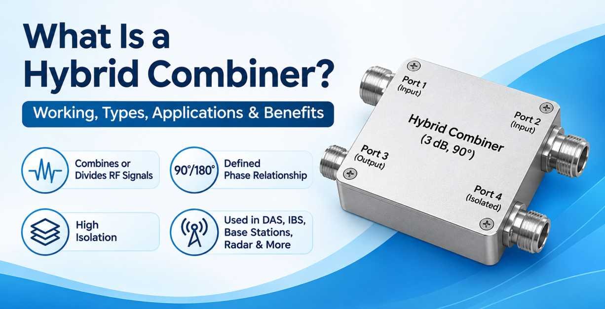
A hybrid combiner is an important passive RF (Radio Frequency) component used in wireless communication, radar systems, antenna networks, microwave systems, and RF signal distribution applications. It is designed to combine or divide radio frequency signals while maintaining controlled phase and amplitude relationships between the input and output ports.
In modern RF and microwave communication systems, multiple transmitters, receivers, antennas, and signal paths often need to operate together. Managing these signals efficiently requires components that provide reliable signal distribution, isolation, and phase control. A hybrid combiner performs these functions by combining two or more RF signals or splitting an incoming signal into multiple outputs with a defined phase relationship.
A hybrid combiner is commonly known as a 3 dB hybrid coupler or 90-degree hybrid coupler when it provides equal power division with a 90-degree phase difference between its output ports. Depending on its design, it can also provide a 180-degree phase relationship.
Hybrid combiners are widely used in cellular base stations, Distributed Antenna Systems (DAS), In-Building Solutions (IBS), microwave communication links, antenna diversity systems, and other RF infrastructure applications.
Understanding the working principle, specifications, types, and applications of a hybrid combiner helps engineers select the right component for their communication system.
What Is a Hybrid Combiner?
A hybrid combiner is a four-port passive RF device designed to combine two input signals into a common RF network or divide one input signal into two output signals with a specific amplitude and phase relationship.
Unlike a conventional RF power combiner, a hybrid combiner provides an additional level of control over signal distribution. It is designed to maintain a defined phase relationship between signals and provide isolation between specific ports.
A typical 3 dB hybrid combiner has four ports:
- Port 1 – Input Port
- Port 2 – Input or Output Port
- Port 3 – Output Port
- Port 4 – Isolated Port
The exact port functions depend on the operating direction and the manufacturer’s port labelling.
When an RF signal enters one input port, the hybrid combiner distributes the signal between two output ports. Ideally, each output receives half of the input power, equivalent to a 3 dB power division, with a defined phase difference.
When two signals enter the appropriate input ports simultaneously, the device combines them at one output port while ideally cancelling them at the isolated port, provided the signals have the required amplitude and phase relationship.
This characteristic makes hybrid combiners particularly useful in RF systems where signal balance, isolation, and phase control are important.
How Does a Hybrid Combiner Work?
A hybrid combiner works on the principle of electromagnetic coupling and controlled signal distribution. It uses a carefully designed transmission-line structure or coupled microwave circuit to distribute RF energy between multiple ports.
The internal structure creates specific amplitude and phase relationships between the output signals.
In a conventional 3 dB, 90-degree hybrid coupler, the input signal is divided equally between two output ports. Each output receives approximately 50% of the input power, while the two output signals maintain a 90-degree phase difference.
For example, when a 100-watt RF signal enters the input port of an ideal 3 dB hybrid combiner:
- Output Port 1 receives 50 watts.
- Output Port 2 receives 50 watts.
- The phase difference between the two output signals is 90 degrees.
- The isolated port ideally receives no power.
In practical applications, some power is lost because of insertion loss, conductor resistance, dielectric losses, and other imperfections.
Working Principle in Signal Combining
When two RF signals enter the hybrid combiner through the designated input ports, their electromagnetic waves interact inside the device.
Depending on their relative amplitude and phase, the signals combine constructively at one output port and destructively at the other.
Constructive interference occurs when signals arrive in the correct phase relationship, allowing their energy to combine at the desired output.
Destructive interference occurs when signals arrive with the required opposing phase relationship, causing cancellation at the isolated port.
This controlled signal behaviour is particularly useful in antenna combining, balanced amplifier circuits, and microwave signal distribution networks.
Main Components and Port Configuration of a Hybrid Combiner
A typical four-port hybrid combiner consists of four RF ports connected through an internal microwave circuit.
1. Input Port
The input port receives the incoming RF signal. Depending on the application, the input ports can also accept two separate RF signals for combining.
2. Output Port
The output port delivers the combined or divided RF signal to another component, such as an antenna, amplifier, receiver, or transmission line.
3. Isolated Port
The isolated port is designed to provide high isolation from a particular input port. Under ideal operating conditions, the signal entering one input port does not appear at the isolated port.
When two signals are combined, the isolated port can be used to monitor the difference between the signals or connect a suitable termination, depending on the circuit design.
4. Internal Transmission-Line Network
The internal structure controls signal coupling, power division, impedance matching, and phase relationships.
It may consist of coupled transmission lines, branch-line structures, or other microwave circuit configurations.
Types of Hybrid Combiners
Hybrid combiners are available in different configurations depending on their phase characteristics, frequency range, power-handling requirements, and application.
1. 90-Degree Hybrid Combiner
A 90-degree hybrid combiner is one of the most commonly used hybrid RF components. It is also known as a quadrature hybrid coupler.
It divides an input RF signal into two equal-amplitude output signals with a 90-degree phase difference.
The 90-degree phase relationship makes it suitable for applications requiring quadrature signal generation, balanced amplifiers, antenna systems, and RF signal distribution.
Key characteristics:
- Equal power division between two output ports.
- 90-degree phase difference between output signals.
- Typically provides 3 dB nominal coupling.
- High isolation between designated ports.
- Available in different frequency bands.
Applications:
- Cellular communication systems.
- Quadrature modulators and demodulators.
- Balanced RF amplifiers.
- Antenna feed networks.
- Microwave communication equipment.
2. 180-Degree Hybrid Combiner
A 180-degree hybrid combiner is designed to divide or combine RF signals with a 180-degree phase relationship.
It is also commonly known as a rat-race coupler or magic-T hybrid, depending on its physical implementation.
This component is useful in applications where signals must be combined or separated based on their phase relationship.
Key characteristics:
- Provides a 180-degree phase relationship.
- Supports equal power division in typical designs.
- Provides isolation between designated ports.
- Can support sum and difference signal operations.
Applications:
- Radar systems.
- Balanced mixer circuits.
- Antenna feed networks.
- Phase-sensitive RF systems.
- Microwave measurement equipment.
3. Branch-Line Hybrid Combiner
A branch-line hybrid is a type of 90-degree hybrid coupler constructed using interconnected transmission-line sections.
It is commonly implemented using microstrip or stripline technology on a suitable dielectric substrate.
The branch-line structure distributes RF power between two output ports while maintaining the required phase relationship.
Key characteristics:
- Compact microwave circuit design.
- Equal power division in conventional configurations.
- 90-degree phase difference.
- Suitable for PCB-based RF systems.
- Frequency-dependent operating characteristics.
Applications:
- RF printed circuit boards.
- Wireless communication equipment.
- Microwave integrated circuits.
- Balanced amplifier designs.
4. Coupled-Line Hybrid Combiner
A coupled-line hybrid combiner uses electromagnetic coupling between two or more transmission lines to distribute RF energy.
Its performance depends on the coupling coefficient, line spacing, substrate characteristics, and physical design.
Key characteristics:
- Uses coupled transmission-line structures.
- Supports controlled signal distribution.
- Can be designed for different coupling levels.
- Suitable for microwave applications.
Applications:
- RF signal distribution networks.
- Microwave communication systems.
- Antenna networks.
- High-frequency electronic circuits.
Hybrid Combiner vs RF Power Combiner
Although hybrid combiners and conventional RF power combiners perform similar functions, they have different operating characteristics and design objectives.
| Parameter | Hybrid Combiner | RF Power Combiner |
|---|---|---|
| Primary function | Combines or divides signals with controlled phase relationships | Combines multiple RF signals |
| Phase relationship | Defined phase difference | Not necessarily controlled |
| Typical configuration | Four-port device | Two-port, three-port or multiport designs |
| Isolation | Provides isolation between designated ports | Depends on design |
| Power division | Commonly equal 3 dB division | Equal or unequal division |
| Applications | Balanced amplifiers, antenna systems, microwave circuits | Transmitter combining and RF distribution |
The main difference is that a hybrid combiner provides controlled phase characteristics and isolation, making it suitable for applications where signal interaction must be carefully managed.
Important Technical Specifications of a Hybrid Combiner
Selecting the correct hybrid combiner requires understanding its electrical and mechanical specifications. These parameters determine whether the component can operate reliably within a particular RF or microwave system.
1. Frequency Range
The frequency range specifies the minimum and maximum frequencies at which the hybrid combiner is designed to operate.
For example, a hybrid combiner may be designed for:
- 700–2700 MHz
- 800–2500 MHz
- 1–6 GHz
- 2–18 GHz
- 6–18 GHz
The required frequency range depends on the wireless communication standard, antenna system, and RF equipment.
Always select a hybrid combiner that covers the complete operating frequency range of the application.
2. Insertion Loss
Insertion loss represents the amount of RF signal power lost when the signal passes through the device.
For an ideal equal-split 3 dB hybrid combiner, each output receives half the input power.
In practical devices, additional insertion loss occurs because of internal conductor and dielectric losses.
Lower excess insertion loss is generally preferred because it improves overall RF system efficiency.
3. Isolation
Isolation measures how effectively the hybrid combiner prevents unwanted RF signal transmission between designated ports.
High isolation helps reduce unwanted interaction between RF signals and improves the stability of connected equipment.
It is particularly important in transmitter combining, balanced amplifier circuits, and antenna distribution networks.
4. Amplitude Balance
Amplitude balance refers to the difference in signal power between the two output ports.
An ideal equal-split hybrid combiner provides identical output power at both ports.
Better amplitude balance is important in applications that require symmetrical signal distribution.
5. Phase Balance
Phase balance describes how accurately the device maintains the intended phase difference between its output signals.
For a 90-degree hybrid combiner, the ideal phase difference is 90 degrees.
For a 180-degree hybrid combiner, the intended phase difference is 180 degrees.
Phase accuracy is important in antenna arrays, balanced amplifiers, and quadrature signal-processing applications.
6. VSWR (Voltage Standing Wave Ratio)
VSWR indicates how effectively the hybrid combiner matches the characteristic impedance of the connected RF system.
A lower VSWR generally indicates better impedance matching and reduced signal reflection.
Many RF hybrid combiners are designed for 50-ohm impedance systems.
7. Power Handling Capacity
Power handling capacity specifies the maximum RF power that the device can safely handle under defined operating conditions.
It is important to consider both average power and peak power, particularly in pulsed radar and high-power transmitter applications.
Operating above the rated power can cause excessive heating, performance degradation, or permanent component damage.
8. Impedance
Most commercial RF hybrid combiners are designed for a characteristic impedance of 50 ohms.
Maintaining impedance compatibility between the combiner, cables, connectors, antennas, and other RF equipment is essential for minimising reflections.
9. Connector Type
The connector type determines how the hybrid combiner connects to the RF system.
Common connector options include:
- SMA Connectors
- N-Type Connectors
- 2.92mm Connectors
- 3.5mm Connectors
- 7/16 DIN Connectors
- 4.3-10 Connectors
Connector selection depends on operating frequency, power requirements, environmental conditions, and mechanical compatibility.
10. Operating Temperature
The operating temperature range indicates the environmental conditions in which the hybrid combiner can maintain its specified performance.
This specification is particularly important for outdoor telecom installations, industrial RF systems, and equipment installed in temperature-controlled or high-temperature environments.
Applications of Hybrid Combiners
Hybrid combiners are used in several RF and microwave communication applications because of their ability to provide controlled power distribution, phase relationships, and port isolation.
1. Distributed Antenna Systems (DAS)
Distributed Antenna Systems are designed to distribute wireless signals throughout buildings, stadiums, airports, shopping malls, hospitals, and other large facilities.
Hybrid combiners can be integrated into DAS networks to distribute or combine RF signals while maintaining the required signal characteristics.
They are useful in applications where multiple signal paths and antenna branches need to operate together.
2. In-Building Solutions (IBS)
In-Building Solutions improve cellular coverage inside structures where outdoor mobile signals may be weak.
Hybrid combiners can be used in RF distribution networks to manage signal paths between amplifiers, repeaters, and antenna systems.
They support reliable signal distribution in commercial buildings, offices, hotels, and industrial facilities.
3. Cellular Base Stations
Modern cellular base stations use several RF components to transmit and receive wireless signals.
Hybrid combiners can be used in antenna feed networks and transmitter architectures where phase balance and isolation are important.
They help engineers design RF networks with controlled signal distribution.
4. Radar Systems
Radar systems use RF and microwave signals to detect objects, measure distance, and determine movement.
Hybrid combiners are used in radar architectures for signal splitting, combining, phase comparison, and balanced circuit configurations.
Their phase characteristics make them suitable for specialised radar signal-processing applications.
5. Balanced Amplifiers
Balanced RF amplifiers use hybrid couplers to divide an incoming signal between two amplifier paths and recombine the amplified signals.
This arrangement can improve amplifier performance and provide useful characteristics such as improved input and output matching.
The hybrid couplers also help manage signal reflections within the amplifier architecture.
6. Microwave Communication Systems
Microwave communication systems transmit high-frequency signals over dedicated communication links.
Hybrid combiners are used in microwave circuits to divide and combine signals while maintaining the desired phase relationships.
They are useful in microwave transmitters, receivers, and signal-processing networks.
7. Antenna Systems
Hybrid combiners are used in antenna feed networks where signals need to be distributed between multiple antenna elements.
They can support phase-controlled antenna configurations and specialised antenna diversity architectures.
8. Test and Measurement Equipment
RF test and measurement systems require accurate signal distribution and phase control.
Hybrid combiners are used in laboratory equipment, network analysers, microwave test setups, and RF measurement circuits.
They help engineers analyse signal characteristics and evaluate RF system performance.
Benefits of Using a Hybrid Combiner
Hybrid combiners offer several advantages in modern RF and microwave applications.
1. Controlled Power Distribution
They distribute incoming RF signals between multiple ports with defined power ratios, commonly equal 3 dB division.
2. Improved Port Isolation
Their internal design provides isolation between specific ports, helping reduce unwanted signal interaction.
3. Accurate Phase Relationships
Hybrid combiners maintain defined phase differences between output signals, which is essential for balanced RF circuits and antenna systems.
4. Flexible RF System Design
They support different RF architectures, including antenna networks, transmitter systems, balanced amplifiers, and microwave circuits.
5. Reliable Signal Management
Properly selected hybrid combiners help maintain predictable RF performance across connected components.
6. Compact Integration
Many hybrid combiners are available in compact designs that can be integrated into RF equipment, microwave modules, and communication infrastructure.
7. Wide Frequency Availability
Hybrid combiners are manufactured for different frequency ranges, making them suitable for cellular, broadband, and microwave applications.
How to Select the Right Hybrid Combiner
Choosing the right hybrid combiner is essential for achieving reliable RF performance. Engineers should evaluate the following factors before selecting a component.
1. Identify the Required Frequency Band
Determine the operating frequency of your RF system. The hybrid combiner must support the entire required frequency range.
2. Determine the Required Phase Difference
Choose between a 90-degree and 180-degree hybrid combiner based on the circuit design and signal-processing requirements.
3. Check Power Handling Capacity
Select a device that can handle the maximum average and peak RF power expected in the application.
4. Evaluate Insertion Loss
Choose a hybrid combiner with low excess insertion loss to minimise unnecessary signal power reduction.
5. Check Isolation Performance
Verify the isolation specification to ensure that unwanted signals do not interfere with connected RF components.
6. Verify Amplitude and Phase Balance
For applications involving balanced amplifiers, antenna arrays, or quadrature circuits, accurate amplitude and phase balance are important.
7. Confirm Impedance Compatibility
Ensure that the hybrid combiner matches the impedance of the overall RF system, commonly 50 ohms.
8. Select Suitable Connectors
Choose connector interfaces according to the cable assemblies, antennas, and other RF components used in the system.
9. Consider Environmental Conditions
For outdoor telecom applications, consider temperature range, humidity, vibration, and environmental protection requirements.
Hybrid Combiner Installation and Maintenance
Correct installation is important for maintaining the electrical performance and operational reliability of a hybrid combiner.
Consider the following installation practices:
- Verify the port configuration before connecting RF cables.
- Ensure all connected components have compatible impedance.
- Use suitable RF cable assemblies with appropriate frequency ratings.
- Tighten connectors according to the manufacturer’s recommended torque specifications.
- Avoid excessive mechanical stress on connectors and cable interfaces.
- Ensure that the device operates within its specified power and frequency limits.
- Inspect connectors regularly for damage, contamination, and loose connections.
- Use suitable 50-ohm terminations on unused ports when required by the manufacturer’s design and application.
Regular inspection and appropriate handling help maintain reliable RF connectivity and minimise performance degradation.
Common Challenges When Using Hybrid Combiners
Although hybrid combiners provide several advantages, incorrect selection or installation can affect system performance.
1. Incorrect Frequency Selection
Using a hybrid combiner outside its specified frequency range can result in higher insertion loss, poor isolation, and incorrect phase performance.
2. Impedance Mismatch
Connecting components with incompatible impedance can increase signal reflections and reduce power-transfer efficiency.
3. Poor Connector Installation
Loose or damaged connectors may introduce additional losses and unreliable RF connections.
4. Excessive Input Power
Operating beyond the rated power capacity can lead to excessive heat generation and permanent device damage.
5. Phase Imbalance
Differences in cable length, component characteristics, or operating frequency can affect the overall phase relationship in the RF system.
6. Improper Port Termination
Leaving a port unterminated when the circuit requires a matched load can cause signal reflections and affect the expected operation of the hybrid network.
Difference Between a 90-Degree Hybrid Combiner and a 180-Degree Hybrid Combiner
Both devices are designed to control RF signal distribution, but they differ in their phase characteristics and applications.
| Parameter | 90-Degree Hybrid | 180-Degree Hybrid |
|---|---|---|
| Phase relationship | 90 degrees | 180 degrees |
| Common name | Quadrature hybrid | Rat-race hybrid |
| Power division | Typically equal | Typically equal |
| Main function | Quadrature signal distribution | Sum and difference signal operations |
| Applications | Balanced amplifiers, antenna systems | Radar, balanced mixers, phase comparison |
| Circuit design | Branch-line or coupled-line structures | Rat-race or magic-T structures |
The choice depends on the phase relationship required by the RF system.
Why Is a Hybrid Combiner Important in Modern Telecommunication Infrastructure?
Modern telecommunication infrastructure requires reliable signal distribution to support multiple frequency bands, antennas, transmitters, and receivers.
As wireless communication networks continue to develop, RF components must support increasingly complex signal architectures.
Hybrid combiners contribute to these systems by providing controlled power division, signal combining, and phase management.
In cellular networks, DAS installations, IBS networks, and microwave communication systems, hybrid combiners can help engineers develop RF architectures that meet specific performance requirements.
They are particularly valuable in applications where maintaining signal balance, reducing unwanted interactions, and managing multiple RF signal paths are essential.
For telecom infrastructure manufacturers, system integrators, and RF engineers, selecting the correct hybrid combiner is an important part of developing an efficient and reliable communication network.
Conclusion
A hybrid combiner is an essential passive RF and microwave component used for combining and dividing signals while maintaining specific phase relationships and isolation between designated ports.
Available in different configurations, including 90-degree and 180-degree hybrid designs, these components are widely used in cellular communication, DAS, IBS, radar, balanced amplifiers, antenna networks, and microwave systems.
When selecting a hybrid combiner, it is important to evaluate frequency range, insertion loss, isolation, phase balance, amplitude balance, VSWR, power handling capacity, impedance, and connector compatibility.
Choosing the correct hybrid combiner helps ensure reliable RF signal distribution and consistent performance in modern wireless communication infrastructure.
Frequently Asked Questions (FAQs) About Hybrid Combiners
1. What is a hybrid combiner in RF?
A hybrid combiner is a passive RF component that combines or divides radio frequency signals while maintaining a defined amplitude and phase relationship between its ports. It is commonly used in antenna systems, balanced amplifiers, and microwave communication networks.
2. What is the main function of a hybrid combiner?
The main function of a hybrid combiner is to distribute or combine RF signals while providing controlled phase relationships and isolation between specific ports.
3. What is a 3 dB hybrid combiner?
A 3 dB hybrid combiner is a device that divides an input RF signal into two equal-power output signals. Ideally, each output receives 50% of the input power, with a defined phase relationship.
4. What is the difference between a 90-degree and 180-degree hybrid combiner?
A 90-degree hybrid combiner provides a 90-degree phase difference between its output signals, whereas a 180-degree hybrid combiner provides a 180-degree phase relationship. Both are used in different RF and microwave circuit configurations.
5. How many ports does a hybrid combiner have?
A conventional hybrid combiner typically has four ports: two input ports, one output port, and one isolated port. The exact port functionality depends on the device configuration and operating direction.
6. What is the difference between a hybrid combiner and a power divider?
A conventional power divider distributes an input signal between multiple output ports. A hybrid combiner also divides or combines signals but provides controlled phase relationships and isolation between designated ports.
7. What is isolation in a hybrid combiner?
Isolation refers to the ability of a hybrid combiner to prevent RF signal transmission between specific ports. High isolation reduces unwanted signal interaction and helps improve RF system performance.
8. What is the typical impedance of a hybrid combiner?
Most commercial RF hybrid combiners are designed for 50-ohm impedance systems. However, the required impedance should always be verified from the manufacturer’s datasheet.
9. Where are hybrid combiners used?
Hybrid combiners are commonly used in cellular base stations, Distributed Antenna Systems, In-Building Solutions, radar systems, balanced amplifiers, antenna feed networks, microwave communication systems, and RF test equipment.
10. Can a hybrid combiner be used as a power divider?
Yes. A hybrid combiner can operate as a power divider by accepting an RF signal at one port and distributing it between two output ports with a defined phase relationship.
11. What is the insertion loss of a hybrid combiner?
Insertion loss represents the signal power lost during transmission through the component. An equal-split 3 dB hybrid has a nominal 3 dB power division at each output, in addition to any excess insertion loss caused by the device.
12. Why is phase balance important in a hybrid combiner?
Phase balance ensures that output signals maintain the required phase difference. It is important for balanced amplifiers, antenna arrays, quadrature circuits, and other phase-sensitive RF applications.
13. What connectors are available for hybrid combiners?
Depending on the frequency and power requirements, hybrid combiners may be available with SMA, N-Type, 2.92mm, 3.5mm, 7/16 DIN, and 4.3-10 connector interfaces.
14. How do I choose the correct hybrid combiner?
Consider the operating frequency, phase difference, insertion loss, isolation, VSWR, power handling capacity, impedance, connector type, and environmental requirements before selecting a hybrid combiner.
15. Is a hybrid combiner an active or passive RF component?
A hybrid combiner is a passive RF component. It does not require an external power supply to perform its signal combining or dividing function.