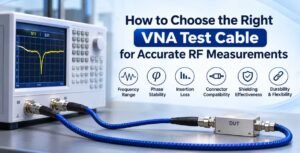
Accurate RF measurements are essential for testing, designing, and validating modern radio frequency and microwave systems. Whether you are measuring insertion loss, return loss, VSWR, impedance, or S-parameters, the quality of your measurement setup directly affects the reliability of your results. One component that plays a particularly important role in this process is the VNA test cable.
A Vector Network Analyzer (VNA) is a sophisticated instrument used to characterize the electrical performance of RF and microwave components. However, even a high-performance VNA cannot deliver reliable measurements if the test cables introduce excessive insertion loss, phase instability, impedance mismatches, or unwanted signal reflections.
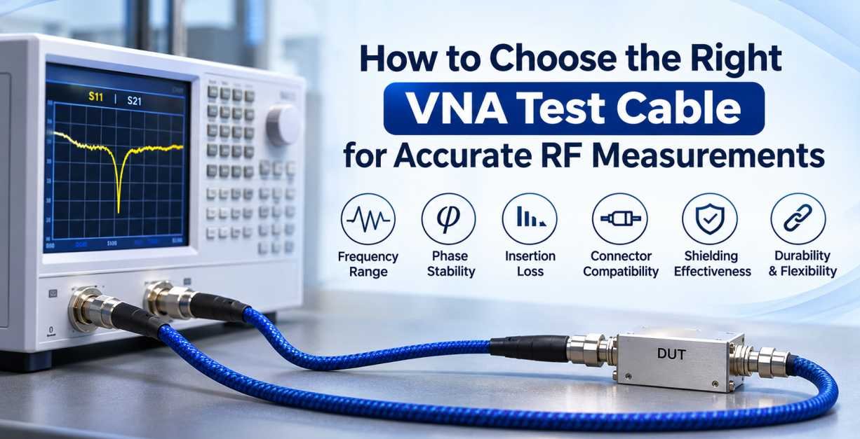
Choosing the right VNA test cable is therefore essential for achieving repeatable, stable, and accurate RF measurements. Factors such as operating frequency, phase stability, cable flexibility, connector compatibility, shielding effectiveness, and mechanical durability should all be considered before selecting a cable assembly.
In this comprehensive guide, we will explain how to choose the right VNA test cable, understand its important specifications, identify common selection mistakes, and improve measurement accuracy in RF and microwave testing applications.
1. What Is a VNA Test Cable?
A VNA test cable is a specialized coaxial cable assembly designed to connect a Vector Network Analyzer to a device under test (DUT). It carries RF signals between the analyzer and the component being measured while maintaining the electrical characteristics required for accurate testing.
Unlike ordinary RF cables, VNA test cables are engineered to provide consistent electrical performance across repeated measurements. They are particularly important in applications where even small variations in phase, amplitude, or impedance can affect the measurement results.
VNA test cables are commonly used for:
- Measuring S-parameters (S11, S21, S12, and S22).
- Characterizing RF filters and amplifiers.
- Testing antennas and antenna systems.
- Measuring insertion loss and return loss.
- Evaluating impedance matching.
- Testing RF connectors and cable assemblies.
- Performing microwave component characterization.
- Conducting laboratory and production-line RF testing.
The primary purpose of a VNA test cable is to provide a stable and predictable signal path between the measurement instrument and the device under test.
2. Why Is Choosing the Right VNA Test Cable Important?
The performance of a VNA measurement setup depends on several interconnected components, including the analyzer, calibration standards, test cables, adapters, connectors, and the device under test.
A poor-quality test cable can introduce measurement errors even when the VNA itself is highly accurate.
Here are some important reasons why selecting the correct cable matters.
Measurement Accuracy
The cable must maintain controlled impedance and low signal loss to prevent unwanted reflections and measurement errors. Poor impedance matching can affect return loss and VSWR readings.
Phase Stability
Phase stability is particularly important when measuring electrical length, phase differences, group delay, and antenna characteristics. Cable movement, bending, and temperature changes can alter the electrical phase of the transmitted signal.
Repeatability
A good VNA test cable provides consistent measurement results when the same test is repeated under similar conditions. This is essential for quality control, product validation, and research applications.
Reduced Measurement Uncertainty
Cable loss, connector mismatches, phase variations, and mechanical instability contribute to measurement uncertainty. Selecting an appropriate cable helps minimize these unwanted effects.
Long-Term Reliability
VNA test cables are frequently connected, disconnected, and repositioned during testing. Durable construction and reliable connectors help maintain performance over repeated measurement cycles.
3. Key Factors to Consider When Choosing a VNA Test Cable
Selecting the right VNA test cable requires evaluating its electrical, mechanical, and environmental characteristics.
The following factors should be considered before purchasing a VNA cable assembly.
3.1 Operating Frequency Range
The first specification to check when selecting a VNA test cable is its operating frequency range.
Every cable assembly is designed to operate within a particular frequency range. Using a cable beyond its specified frequency limit can increase insertion loss, cause impedance variations, and reduce measurement accuracy.
For example:
- Low-frequency RF testing may require cables operating up to a few hundred megahertz.
- General RF testing may require cables covering frequencies up to 6 GHz or 18 GHz.
- Microwave measurements may require cable assemblies operating up to 26.5 GHz or 40 GHz.
- High-frequency microwave and millimeter-wave testing may require specialized assemblies operating at 50 GHz, 67 GHz, or higher.
The required frequency range depends on the VNA model and the device under test.
Selection Tip: Always select a VNA test cable with a specified maximum frequency that meets or exceeds your application’s highest measurement frequency. Also verify that the connectors, adapters, and calibration standards support the same frequency range.
3.2 Phase Stability
Phase stability is one of the most important characteristics of a high-performance VNA test cable.
In RF measurements, phase describes the relative position of a signal waveform over time. When a cable is bent, twisted, stretched, or exposed to temperature variations, its electrical length may change, resulting in phase variations.
These variations can affect measurements involving:
- S-parameters.
- Group delay.
- Phase matching.
- Antenna radiation characteristics.
- Differential measurements.
- High-frequency component characterization.
VNA cables are generally available with different levels of phase stability.
Static Phase Stability: Designed for applications where the cable remains stationary during measurement.
Flex Phase Stability: Designed to maintain consistent electrical performance when the cable is repeatedly flexed during testing.
High-Flex Phase Stability: Suitable for applications involving frequent movement and repeated positioning, depending on the cable’s specified performance.
Selection Tip: If your testing procedure requires frequent cable movement, choose a phase-stable or high-flex VNA test cable rather than a standard flexible coaxial cable.
3.3 Amplitude Stability
Amplitude stability refers to the ability of a cable to maintain consistent signal transmission when its physical position or environmental conditions change.
Cable movement can affect attenuation and impedance characteristics, especially at higher frequencies.
Unstable amplitude performance can lead to variations in:
- Insertion loss measurements.
- Transmission measurements.
- Gain measurements.
- Return loss measurements.
- Signal amplitude comparisons.
For accurate measurements, select a VNA cable with low amplitude variation under its specified operating conditions.
Amplitude stability and phase stability are particularly important when performing repeated measurements on sensitive RF components.
3.4 Insertion Loss
Insertion loss represents the reduction in signal power as an RF signal travels through a cable assembly.
It is generally expressed in decibels (dB).
A cable with excessive insertion loss can reduce the signal level reaching the device under test or returning to the analyzer. This can affect the measurement dynamic range and uncertainty.
Insertion loss depends on several factors:
- Cable length.
- Operating frequency.
- Conductor material.
- Dielectric material.
- Cable diameter.
- Connector design.
- Cable construction.
Generally, longer cables and higher operating frequencies result in greater attenuation.
For example, a short VNA cable assembly may provide lower insertion loss than a longer assembly made from the same cable type.
Selection Tip: Choose a cable with sufficiently low insertion loss for your measurement frequency and required dynamic range. Avoid unnecessarily long cables because additional cable length can increase signal attenuation.
3.5 Return Loss and VSWR
Return loss and Voltage Standing Wave Ratio (VSWR) are important parameters for evaluating impedance matching in RF systems.
A VNA test cable should maintain good impedance characteristics throughout its operating frequency range.
Return Loss: Indicates how much signal power is reflected because of impedance mismatch. Higher return loss generally indicates better matching.
VSWR: Describes the relationship between maximum and minimum voltage levels in a standing wave pattern. A VSWR closer to 1:1 indicates better impedance matching.
Poor-quality cables, damaged connectors, and improperly assembled interfaces can introduce reflections that affect measurement accuracy.
For most standard RF measurement systems, 50-ohm impedance is commonly used. Therefore, the cable assembly should match the impedance of the VNA and device under test.
3.6 Connector Compatibility
Connector compatibility is another critical consideration when selecting a VNA test cable.
Even a high-performance cable cannot provide reliable measurements if its connectors are incompatible with the VNA ports or the device under test.
Common RF connectors used in VNA test cable assemblies include:
- SMA Connectors
- 3.5mm Connectors
- 2.92mm Connectors (K-Type)
- 2.4mm Connectors
- 1.85mm Connectors (V-Type)
- 1.0mm Connectors
- N-Type Connectors
- 7/16 DIN Connectors
Each connector has specific mechanical and electrical characteristics, including frequency limitations, interface dimensions, and mating requirements.
| Connector Type | Common Application |
|---|---|
| SMA | General RF and microwave testing |
| 3.5mm | Precision RF and microwave measurements |
| 2.92mm | Microwave testing up to 40 GHz |
| 2.4mm | High-frequency microwave testing |
| 1.85mm | Millimeter-wave measurements up to 67 GHz |
| 1.0mm | Very high-frequency measurements, typically up to 110 GHz |
| N-Type | General-purpose RF testing |
| 7/16 DIN | RF infrastructure and high-power applications |
Note: Frequency limits depend on the connector design, manufacturer specifications, and mating interface. The values above are typical application ranges, not universal ratings.
Selection Tip: Check the connector type, gender, interface compatibility, and frequency rating at both ends of the cable assembly. Avoid mixing precision connector interfaces without confirming their compatibility.
3.7 Cable Length
Cable length directly affects the electrical performance and convenience of a VNA measurement setup.
Longer cables generally introduce more insertion loss and may increase measurement uncertainty.
However, very short cables may restrict positioning and make it difficult to connect the DUT safely.
Consider the following factors when selecting cable length:
- Distance between the VNA and DUT.
- Required measurement frequency.
- Cable routing requirements.
- Available laboratory space.
- Connector accessibility.
- Mechanical movement during testing.
- Required phase stability.
Common VNA cable lengths include 0.3 m, 0.5 m, 1 m, 1.5 m, and 2 m, although customized lengths are also available.
Selection Tip: Choose the shortest practical cable length that allows convenient connection without excessive mechanical stress.
3.8 Shielding Effectiveness
Shielding helps protect RF signals from external electromagnetic interference (EMI) and radio frequency interference (RFI).
A well-shielded VNA cable reduces unwanted signal coupling and helps maintain measurement consistency.
Shielding performance depends on:
- Number of shielding layers.
- Braid coverage.
- Foil construction.
- Connector termination quality.
- Overall cable design.
In laboratories and testing environments containing multiple RF instruments, transmitters, or switching systems, effective shielding is particularly important.
Selection Tip: Choose a VNA cable with suitable shielding performance for the electromagnetic environment in which measurements will be performed.
3.9 Mechanical Flexibility and Durability
Mechanical flexibility is important because VNA test cables are often repositioned to connect different devices under test.
However, excessive bending, twisting, and stretching can damage the cable structure and change its electrical characteristics.
Before selecting a cable, evaluate:
- Minimum bending radius.
- Flex life.
- Torsional resistance.
- Jacket material.
- Connector strain relief.
- Mechanical durability.
- Resistance to repeated handling.
A cable designed for static laboratory measurements may not be suitable for automated test systems where repeated movement is required.
Selection Tip: Match the cable’s mechanical construction to the testing environment. For repeated movement, choose a cable specifically designed and tested for dynamic flex applications.
3.10 Temperature Stability
Temperature variations can influence the electrical characteristics of coaxial cables.
Changes in conductor dimensions and dielectric properties can affect cable attenuation, impedance, and electrical phase.
This is particularly important when performing high-precision measurements or testing components in temperature-controlled chambers.
Check the following specifications:
- Operating temperature range.
- Temperature coefficient of phase.
- Temperature coefficient of attenuation.
- Temperature-related amplitude stability.
- Thermal cycling performance.
For applications requiring highly repeatable measurements, temperature-stable VNA cable assemblies are recommended.
4. Types of VNA Test Cables
Different VNA testing applications require different cable constructions. Understanding the available cable types helps identify the most suitable option for your measurement requirements.
4.1 Flexible VNA Test Cables
Flexible VNA test cables are designed for applications where the cable needs to be routed or repositioned during testing.
They offer convenient handling and are commonly used in RF laboratories, engineering development, and general-purpose measurement setups.
Key characteristics include:
- Flexible cable construction.
- Convenient routing and installation.
- Availability in different lengths.
- Compatibility with various RF connector interfaces.
- Suitability for general RF and microwave testing, depending on specifications.
Flexible VNA cables are suitable when convenience and cable positioning are important considerations.
4.2 Phase-Stable VNA Test Cables
Phase-stable VNA cables are engineered to minimize electrical phase variations caused by cable movement, bending, and environmental changes.
They are particularly useful for precision measurements where even small phase variations can affect the results.
Common applications include:
- Vector network analysis.
- Antenna characterization.
- Phase-sensitive measurements.
- Microwave component testing.
- RF research and development.
These cables generally feature specialized dielectric materials, controlled cable construction, and optimized mechanical designs.
4.3 High-Frequency VNA Test Cables
High-frequency VNA test cables are designed for microwave and millimeter-wave measurements.
They support higher operating frequencies and require precision-engineered conductors, dielectric materials, shielding, and connectors.
Common applications include:
- 5G and advanced wireless communication testing.
- Millimeter-wave component characterization.
- High-frequency filters and amplifiers.
- RF semiconductor testing.
- Microwave laboratory measurements.
Connector selection is especially important for high-frequency applications because small mechanical imperfections can significantly affect electrical performance.
4.4 Low-Loss VNA Test Cables
Low-loss VNA cables are designed to minimize signal attenuation over the specified frequency range.
They are useful when measurements require a longer connection between the VNA and DUT or when maintaining sufficient signal level is important.
Important characteristics include:
- Low attenuation.
- Controlled impedance.
- Consistent transmission performance.
- Suitable shielding.
- Reliable connector termination.
The actual insertion loss should always be evaluated using manufacturer-provided specifications at the intended operating frequency.
4.5 Armored and Ruggedized VNA Test Cables
Armored or ruggedized VNA test cables are designed for testing environments where cables may experience mechanical stress, abrasion, or frequent handling.
They can provide additional mechanical protection compared with standard cable constructions.
Typical applications include:
- Production testing environments.
- Field measurement systems.
- Industrial RF testing.
- Automated test equipment.
- Laboratory setups involving frequent cable movement.
However, additional mechanical protection does not automatically guarantee better phase stability. Always verify the electrical specifications separately.
5. Understanding Important VNA Test Cable Specifications
Before purchasing a VNA cable assembly, it is important to understand the technical specifications provided by the manufacturer.
The following table summarizes the major parameters to evaluate.
| Specification | What It Indicates | Why It Matters |
|---|---|---|
| Frequency Range | Supported operating frequencies | Ensures compatibility with the VNA |
| Impedance | Nominal characteristic impedance | Maintains proper impedance matching |
| Insertion Loss | Signal attenuation through the cable | Affects signal level and dynamic range |
| Return Loss | Signal reflection performance | Helps evaluate impedance matching |
| VSWR | Standing wave ratio | Indicates impedance mismatch |
| Phase Stability | Phase variation under specified conditions | Supports repeatable measurements |
| Amplitude Stability | Signal level variation | Improves measurement consistency |
| Connector Type | Interface at both cable ends | Ensures physical and electrical compatibility |
| Cable Length | Overall assembly length | Influences attenuation and usability |
| Shielding | Protection against external interference | Reduces unwanted signal coupling |
| Bending Radius | Minimum recommended bending radius | Helps prevent mechanical damage |
| Temperature Range | Permitted operating temperatures | Ensures environmental suitability |
A good selection process involves comparing these specifications against the actual requirements of the measurement application rather than choosing a cable based only on its frequency rating.
6. How VNA Test Cables Affect S-Parameter Measurements
S-parameters are fundamental to RF and microwave network analysis. They describe how electrical signals behave when they interact with a device or network.
A Vector Network Analyzer measures these parameters to characterize the performance of RF components.
The most commonly measured S-parameters in a two-port network are:
S11 – Input Reflection Coefficient
S11 describes the amount of signal reflected from the input port of a device.
It is commonly used to evaluate:
- Input impedance matching.
- Antenna return loss.
- Filter input matching.
- RF component reflection characteristics.
A poorly matched VNA test cable can introduce additional reflections and influence S11 measurements.
S21 – Forward Transmission Coefficient
S21 represents the signal transmitted from Port 1 to Port 2.
It is commonly used to evaluate:
- Insertion loss.
- Amplifier gain.
- Filter transmission characteristics.
- Cable transmission performance.
Excessive test cable attenuation can affect the measured transmission level if the measurement setup is not properly calibrated.
S12 – Reverse Transmission Coefficient
S12 represents the transmission from Port 2 to Port 1.
It is useful for measuring reverse transmission and evaluating the isolation characteristics of certain RF components.
S22 – Output Reflection Coefficient
S22 describes the reflected signal at the output port.
It is commonly used to evaluate output impedance matching and reflection performance.
For accurate S-parameter measurements, the test cables must have stable electrical characteristics and appropriate calibration must be performed at the intended measurement reference planes.
7. Why VNA Calibration Is Important When Using Test Cables
Calibration is one of the most important steps in achieving accurate VNA measurements.
Even high-quality test cables introduce electrical effects such as attenuation, phase delay, and impedance mismatch.
Calibration helps the VNA compensate for systematic measurement errors within the calibrated setup.
Common VNA calibration techniques include the following.
7.1 SOLT Calibration
SOLT stands for Short, Open, Load, and Thru.
It is a widely used calibration technique for RF and microwave measurements.
The calibration process uses known standards to characterize and correct systematic errors in the measurement system.
SOLT calibration is commonly used with coaxial VNA test cables and compatible calibration kits.
7.2 TRL Calibration
TRL stands for Thru, Reflect, and Line.
This method uses transmission lines and reflection standards to establish measurement reference planes.
TRL calibration is particularly useful in certain microwave, planar, and fixture-based measurement applications where suitable calibration standards are available.
7.3 Electronic Calibration
Electronic calibration (ECal) uses an electronic calibration module to perform calibration automatically.
It reduces manual connection steps and helps improve testing convenience.
ECal modules are available for different frequency ranges and connector interfaces.
7.4 Port Extension and De-Embedding
Port extension adjusts the electrical reference plane to compensate for a known electrical delay.
De-embedding removes the characterized electrical effects of fixtures, adapters, cables, or other structures from measurement results.
These techniques can be useful in advanced RF testing, but they are not substitutes for a properly characterized and calibrated measurement setup.
Important: Perform calibration using the same test cables, adapters, and connection configuration that will be used during measurement. If the cables are moved significantly after calibration, check whether recalibration is necessary, particularly for phase-sensitive measurements.
8. How to Select the Right VNA Test Cable for Different Applications
Different industries and testing environments have different requirements for VNA cable assemblies.
8.1 Antenna Testing
Antenna testing involves measuring parameters such as return loss, impedance, bandwidth, and radiation-related characteristics.
For these applications, choose a cable with:
- Suitable operating frequency range.
- Good phase stability.
- Low insertion loss.
- Compatible RF connectors.
- Appropriate flexibility.
- Reliable shielding.
Cable movement during antenna testing can influence phase-sensitive measurements, so the cable should be positioned and secured consistently.
8.2 5G and Wireless Communication Testing
Modern wireless communication systems operate across different RF and microwave frequency bands.
Testing 5G components, antennas, filters, and RF modules requires cable assemblies with appropriate frequency support and stable electrical characteristics.
Important selection factors include:
- Frequency coverage.
- Phase stability.
- Low insertion loss.
- Connector precision.
- Shielding effectiveness.
- Repeatability.
The required specifications depend on the frequency bands and measurement setup being used.
8.3 Microwave Component Testing
Microwave testing often involves high-frequency components such as filters, couplers, amplifiers, attenuators, and power dividers.
At higher frequencies, connector precision and cable construction become increasingly important.
Recommended considerations include:
- Precision microwave connectors.
- Low insertion loss.
- Good return loss.
- Stable phase performance.
- Controlled impedance.
- Proper calibration compatibility.
8.4 RF Cable Assembly Testing
When testing RF cable assemblies, the VNA is used to evaluate insertion loss, return loss, impedance characteristics, and transmission performance.
A suitable VNA test cable should offer stable performance and compatible connectors.
It is also important to avoid unnecessary adapters because every additional connection can introduce potential mismatch and measurement uncertainty.
8.5 Production-Line Testing
Production testing requires consistent measurements across multiple products and repeated test cycles.
The ideal VNA test cable should offer:
- High mechanical durability.
- Repeatable electrical performance.
- Appropriate flex life.
- Secure connector interfaces.
- Suitable operating frequency.
- Compatibility with automated test equipment.
For automated testing, verify the manufacturer’s specifications for mating cycles and flex life rather than assuming all phase-stable cables offer the same durability.
9. Common Mistakes to Avoid When Choosing a VNA Test Cable
Selecting a VNA test cable based only on price or connector compatibility can lead to inaccurate measurements and unnecessary replacement costs.
Here are some common mistakes to avoid.
Choosing a Cable Without Checking Its Frequency Rating
A cable that works well at lower frequencies may not deliver the required performance at higher frequencies.
Always check the specified frequency range before purchasing.
Ignoring Phase Stability
Using a standard flexible coaxial cable for precision phase measurements can introduce unwanted variations.
Select a phase-stable cable when the application requires consistent phase performance.
Using Incorrect Connector Interfaces
Connector interfaces that appear physically similar may have different mechanical dimensions and electrical characteristics.
Verify the exact connector series, gender, and mating compatibility.
Selecting Excessive Cable Length
Long cables can increase insertion loss and may introduce additional measurement uncertainty.
Choose an appropriate length based on the measurement arrangement.
Ignoring Cable Movement After Calibration
Moving or bending a cable after calibration can change its electrical characteristics.
For precision measurements, keep the cable in a consistent position or recalibrate the setup when necessary.
Overlooking Connector Quality
Damaged, contaminated, or poorly manufactured connectors can affect return loss and repeatability.
Always inspect the connector interfaces before making measurements.
Exceeding the Minimum Bending Radius
Excessive bending can damage the cable structure and affect electrical performance.
Follow the manufacturer’s recommended bending radius and handling instructions.
10. Best Practices for Maintaining VNA Test Cables
Proper handling and maintenance help preserve the electrical and mechanical performance of VNA test cable assemblies.
Follow these recommendations to improve cable reliability.
1. Inspect connectors regularly: Check for damaged threads, worn mating surfaces, dirt, and debris before connecting the cable.
2. Use appropriate connector torque: Follow the connector manufacturer’s recommended torque values and use a suitable torque wrench for precision interfaces.
3. Avoid excessive bending: Maintain the specified minimum bending radius during installation and testing.
4. Prevent unnecessary twisting: Avoid rotating the cable body while tightening connectors.
5. Use protective caps: Cover unused connector interfaces to protect them from dust and physical damage.
6. Store cables properly: Use suitable storage arrangements to prevent sharp bends, crushing, and mechanical stress.
7. Avoid pulling from connectors: Handle the cable body carefully rather than using the connector as a pulling point.
8. Monitor measurement performance: Periodically check cable insertion loss, return loss, and phase stability against baseline measurements.
9. Recalibrate when required: Perform a new calibration whenever cable movement or configuration changes could compromise measurement accuracy.
10. Follow manufacturer specifications: Observe the recommended operating temperature, handling limits, and mechanical ratings.
11. VNA Test Cable vs Standard RF Coaxial Cable
Although VNA test cables and standard RF coaxial cables may look similar, their intended performance requirements can be different.
| Parameter | Standard RF Coaxial Cable | VNA Test Cable |
|---|---|---|
| Primary Purpose | General RF signal transmission | Precision RF measurements |
| Phase Stability | Depends on cable construction | Often specifically optimized |
| Amplitude Stability | Varies by cable type | May be specified for measurement applications |
| Connector Quality | General RF requirements | Often precision measurement interfaces |
| Mechanical Performance | Depends on construction | Available in static and dynamic test configurations |
| Measurement Repeatability | Not necessarily optimized | Designed to support repeatable measurements |
| Applications | RF communication and signal distribution | VNA, microwave, and component testing |
A standard coaxial cable may be suitable for certain measurement applications, but it should not automatically be considered a replacement for a precision VNA test cable.
The correct choice depends on the required frequency range, measurement uncertainty, phase stability, and mechanical operating conditions.
12. How to Evaluate a VNA Test Cable Before Purchasing
Before finalizing a VNA test cable, review the manufacturer’s datasheet and verify that the cable meets your application requirements.
Pay particular attention to the following technical details:
Electrical Performance
- Operating frequency range.
- Characteristic impedance.
- Insertion loss versus frequency.
- Return loss or VSWR versus frequency.
- Phase stability.
- Amplitude stability.
- Shielding performance.
Mechanical Performance
- Cable diameter.
- Minimum bending radius.
- Cable flexibility.
- Flex life and mating cycle specifications.
- Jacket material.
- Operating temperature.
Connector Configuration
- Connector type at both ends.
- Male or female interface.
- Connector frequency rating.
- Precision interface compatibility.
- Connector durability.
Documentation and Quality
- Manufacturer datasheet.
- Test reports, where available.
- Measurement conditions.
- Calibration compatibility.
- Quality inspection and traceability information.
Do not compare two VNA test cables using only their maximum frequency ratings. A cable rated for a higher frequency is not automatically better for every application.
The most suitable cable is the one that meets the complete electrical and mechanical requirements of your measurement system.
13. Future Trends in VNA Test Cable Technology
As RF and microwave technologies continue to evolve, the demand for high-performance measurement accessories is increasing.
Several developments are influencing the design and application of modern VNA test cables.
Higher Frequency Measurement Requirements
The growth of millimeter-wave research, advanced wireless communication, satellite communication, and high-frequency semiconductor testing is increasing the need for precision cable assemblies operating at higher frequencies.
Improved Phase Stability
Manufacturers continue to develop cable constructions designed to reduce phase variations caused by bending, temperature changes, and mechanical movement.
Advanced Cable Materials
Improvements in dielectric materials, conductor construction, shielding, and protective jackets are helping manufacturers optimize electrical and mechanical performance.
Automated RF Testing
Automated measurement systems require cables that can withstand repeated movement while maintaining consistent electrical characteristics.
This is increasing the importance of flex life, phase stability, connector reliability, and repeatability.
Higher Measurement Accuracy
As RF systems become more complex, engineers require measurement accessories that help reduce uncertainty and maintain consistent results across testing environments.
These developments make proper VNA test cable selection increasingly important for modern RF and microwave engineering.
14. Frequently Asked Questions (FAQs) About VNA Test Cables
1. What is a VNA test cable used for?
A VNA test cable connects a Vector Network Analyzer to a device under test (DUT). It provides a controlled RF signal path for measuring S-parameters, insertion loss, return loss, impedance, phase, and other electrical characteristics.
2. What is the difference between a VNA test cable and an RF cable?
A standard RF cable is primarily designed for signal transmission, whereas a VNA test cable is designed for precision measurements. VNA cables may offer improved phase stability, amplitude stability, connector precision, and measurement repeatability.
3. Which frequency range should I choose for a VNA test cable?
Choose a cable that supports the highest frequency required by your application. Common options include 6 GHz, 18 GHz, 26.5 GHz, 40 GHz, 50 GHz, and 67 GHz. Always verify the actual cable and connector specifications.
4. Why is phase stability important in VNA test cables?
Phase stability ensures that the electrical phase of the transmitted signal remains consistent during measurement. It is particularly important for S-parameter testing, group delay measurements, antenna characterization, and phase-sensitive applications.
5. What impedance is commonly used in VNA test cables?
Most RF and microwave VNA measurement systems use 50-ohm test cables. The cable impedance should match the VNA ports, calibration standards, and device under test.
6. Which connectors are commonly used in VNA test cables?
Common connector interfaces include SMA, 3.5mm, 2.92mm, 2.4mm, 1.85mm, and 1.0mm. The appropriate connector depends on the operating frequency, measurement requirements, and equipment interface.
7. Does cable length affect VNA measurement accuracy?
Yes. Longer cables generally introduce greater insertion loss and additional electrical delay. Cable length can also influence measurement uncertainty. Selecting the shortest practical cable helps minimize unnecessary signal loss.
8. Can I use a standard coaxial cable for VNA measurements?
Yes, standard coaxial cables can be used for certain general-purpose measurements if their electrical specifications are suitable. However, precision measurements may require specialized VNA cables with better phase and amplitude stability.
9. How often should VNA test cables be calibrated?
VNA test cables are not generally calibrated independently at fixed universal intervals. Instead, the VNA measurement system should be calibrated according to the application’s accuracy requirements and measurement procedure. Cable performance should also be inspected periodically.
10. How can I improve the repeatability of VNA measurements?
Use phase-stable cables, maintain consistent cable positioning, use precision connectors, follow proper connector torque specifications, avoid unnecessary adapters, and perform calibration at the intended measurement reference plane.
11. What is the importance of low insertion loss in VNA test cables?
Low insertion loss helps preserve signal strength between the VNA and the device under test. It is particularly important for high-frequency measurements and applications requiring a wide measurement dynamic range.
12. What should I check before purchasing a VNA test cable?
Check the frequency range, characteristic impedance, insertion loss, return loss, phase stability, amplitude stability, connector compatibility, cable length, bending radius, shielding, and operating temperature.
15. Conclusion
Choosing the right VNA test cable is essential for obtaining accurate, stable, and repeatable RF measurements. Although the Vector Network Analyzer performs the actual measurement, the quality and characteristics of the connecting cable directly influence the overall measurement setup.
Factors such as frequency range, phase stability, amplitude stability, insertion loss, return loss, connector compatibility, cable length, shielding, and mechanical durability should be carefully evaluated before selecting a cable assembly.
For precision RF and microwave applications, selecting a cable based on its complete electrical and mechanical specifications is more important than considering frequency rating or price alone.
Whether you are performing antenna characterization, microwave component testing, 5G development, or production-line RF measurements, the right VNA test cable helps minimize measurement uncertainty and maintain consistent testing performance.
For reliable RF measurement setups, choose cable assemblies that meet your equipment specifications, application requirements, and expected operating conditions.