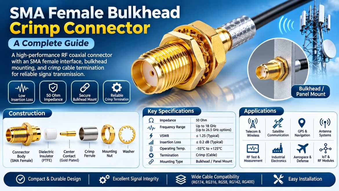
SMA Female Bulkhead Crimp Connectors are widely used RF coaxial connectors designed to provide reliable, secure, and high-performance connections in radio frequency and microwave communication systems. These connectors combine three important features: an SMA female interface, a bulkhead mounting design, and a crimp-style cable termination. This combination makes them suitable for applications where dependable RF signal transmission, secure panel installation, and efficient cable termination are essential.
In modern communication infrastructure, maintaining signal integrity is critical. RF connectors play an important role in connecting antennas, RF cables, transmitters, receivers, amplifiers, wireless communication equipment, and testing instruments. Even a small impedance mismatch or poor electrical connection can result in signal reflection, insertion loss, and reduced system performance.
The SMA Female Bulkhead Crimp Connector is designed to overcome these challenges by providing a compact interface, mechanical stability, and reliable electrical connectivity. Its bulkhead mounting arrangement allows the connector to be installed through an equipment panel or enclosure, while the crimp termination provides a secure connection with compatible coaxial cables.
These connectors are commonly used in telecommunications, wireless communication, antenna systems, RF testing equipment, GPS devices, satellite communication, industrial electronics, and microwave applications.
This comprehensive guide explains what an SMA Female Bulkhead Crimp Connector is, how it works, its construction, features, specifications, applications, advantages, and important factors to consider when selecting the right connector.
What Is an SMA Female Bulkhead Crimp Connector?
An SMA Female Bulkhead Crimp Connector is a type of SubMiniature Version A (SMA) coaxial RF connector designed to connect compatible coaxial cables to electronic equipment through a panel or enclosure.
It consists of three primary design elements:
SMA Female Interface: The connector features an SMA female mating interface with internal coupling threads and a center contact socket. It connects with a compatible SMA male connector.
Bulkhead Mounting: The connector is designed to be mounted through a panel, chassis, or equipment enclosure using a threaded body, mounting nut, and washer, depending on the design.
Crimp Cable Termination: The connector uses a crimp ferrule to secure the cable’s outer braid or shield mechanically to the connector body. The center conductor connection may use a soldered or crimped center contact, depending on the connector design.
The combination of these features provides a reliable RF connection while allowing convenient installation in communication equipment and electronic enclosures.
SMA Female Bulkhead Crimp Connectors are generally designed for 50 Ohm RF systems and are available in different configurations depending on cable type, frequency range, and installation requirements.
How Does an SMA Female Bulkhead Crimp Connector Work?
An SMA Female Bulkhead Crimp Connector works by establishing an electrical connection between a coaxial RF cable and a compatible SMA male connector.
When the SMA male connector is attached, its center pin connects with the female center socket, allowing the RF signal to pass through the connector.
The outer coupling threads secure the mating connection and help maintain mechanical stability.
The connector’s bulkhead mounting section allows it to be fixed to an equipment panel or enclosure. This provides a stable connection point for external RF cables.
The crimp termination secures the coaxial cable to the connector. A compatible crimping tool compresses the ferrule around the cable’s outer braid and connector body, creating a mechanically secure termination.
The electrical signal travels through the center conductor, while the surrounding dielectric and outer conductor maintain the coaxial transmission structure.
Proper impedance matching between the cable and connector helps minimize signal reflections and maintain reliable RF performance.
Construction of an SMA Female Bulkhead Crimp Connector
An SMA Female Bulkhead Crimp Connector consists of several precision-engineered components. Each component contributes to its electrical performance, mechanical strength, and durability.
1. SMA Female Interface
The female interface is the mating section of the connector. It features internal coupling threads and a center socket designed to accept the center pin of a compatible SMA male connector.
The interface provides a secure mechanical connection and reliable electrical contact.
2. Center Contact
The center contact carries the RF signal between the coaxial cable and the mating connector.
It is generally manufactured using conductive materials such as:
- Brass
- Beryllium copper
- Copper alloys
Gold plating is commonly used to improve conductivity, reduce contact resistance, and provide corrosion resistance.
3. Dielectric Insulator
The dielectric insulator separates the center contact from the outer conductor.
Common dielectric materials include:
- PTFE (Polytetrafluoroethylene)
- Other high-performance insulating polymers
PTFE is widely used because of its excellent electrical insulation, low dielectric loss, and temperature stability.
4. Connector Body
The connector body provides mechanical support and forms part of the outer RF conductor.
Common materials include:
- Brass
- Stainless steel
- Other conductive metal alloys
Nickel or gold plating may be used depending on the connector design and application.
5. Bulkhead Mounting Section
The bulkhead section allows the connector to be installed through a mounting hole in an equipment panel or enclosure.
It typically includes:
- Threaded mounting body
- Mounting nut
- Washer
- Panel locking arrangement
This construction helps prevent unwanted movement during cable connection and disconnection.
6. Crimp Ferrule
The crimp ferrule secures the coaxial cable’s outer braid to the connector body.
It is compressed using a compatible crimping tool to create a strong mechanical and electrical connection.
7. Cable Entry Section
The rear section accommodates the compatible coaxial cable and provides the required cable termination arrangement.
The connector must be selected according to the cable’s diameter, dielectric dimensions, and conductor construction.
Key Features of SMA Female Bulkhead Crimp Connectors
SMA Female Bulkhead Crimp Connectors offer several features that make them suitable for professional RF and microwave applications.
Compact Design
The SMA interface has a compact construction, making it suitable for applications where installation space is limited.
Secure Bulkhead Mounting
The threaded mounting body provides a stable connection through equipment panels and enclosures.
Reliable Crimp Termination
The crimp ferrule provides mechanical retention and electrical continuity when correctly installed using compatible tooling.
Excellent Electrical Performance
Precision manufacturing and controlled impedance help maintain signal integrity across the specified frequency range.
50 Ohm Impedance
Most SMA RF connectors are designed for 50 Ohm systems, making them suitable for standard RF communication applications.
Corrosion Resistance
Suitable metal finishes help protect connector surfaces against corrosion and support long-term reliability.
Easy Installation
Crimp termination allows efficient cable assembly without requiring soldering of the outer braid.
Wide Application Compatibility
These connectors are available for different coaxial cable types and equipment mounting arrangements.
SMA Female Bulkhead Crimp Connector Specifications
The technical specifications of an SMA Female Bulkhead Crimp Connector vary according to its manufacturer, cable compatibility, and design.
The following table provides typical reference specifications. Actual ratings must always be verified against the individual product datasheet.
| Specification | Typical Details |
|---|---|
| Connector Type | SMA Female |
| Mounting Type | Bulkhead Mount |
| Cable Termination | Crimp |
| Connector Interface | SMA Female Jack |
| Impedance | 50 Ohms |
| Frequency Range | Up to 18 GHz for many standard designs |
| Extended Frequency | Up to 26.5 GHz for suitable designs |
| Center Contact | Gold-Plated Brass or Copper Alloy |
| Body Material | Brass or Stainless Steel |
| Insulator Material | PTFE |
| Cable Compatibility | Model Dependent |
| Mounting Arrangement | Threaded Bulkhead |
| Coupling Mechanism | Threaded |
| Application | RF and Microwave Systems |
Common Cable Types Used with SMA Female Bulkhead Crimp Connectors
SMA Female Bulkhead Crimp Connectors are available for different coaxial cable configurations.
Selecting the correct connector for the cable is essential to ensure proper mechanical fitting and electrical performance.
RG174 Coaxial Cable
RG174 is a thin, flexible coaxial cable commonly used in compact electronic devices, GPS equipment, wireless modules, and portable communication systems.
SMA bulkhead crimp connectors designed specifically for RG174 cables provide a compact termination solution.
RG316 Coaxial Cable
RG316 is a flexible coaxial cable featuring a PTFE dielectric and a high-temperature-resistant construction.
It is commonly used in:
- Aerospace electronics
- Military communication
- RF test equipment
- Wireless communication devices
- Microwave assemblies
RG58 Coaxial Cable
RG58 is a 50 Ohm coaxial cable used in communication equipment, laboratory setups, and RF installations.
Connectors specifically designed for RG58 are available with suitable crimp ferrules and center contacts.
RG142 Coaxial Cable
RG142 is a high-performance coaxial cable designed for applications requiring improved temperature resistance and electrical stability.
It is commonly used in military, aerospace, and professional RF applications.
RG400 Coaxial Cable
RG400 is a double-shielded coaxial cable with a PTFE dielectric, offering good flexibility, shielding, and temperature performance.
It is widely used in aerospace, defense, and high-performance RF cable assemblies.
Applications of SMA Female Bulkhead Crimp Connectors
SMA Female Bulkhead Crimp Connectors are used in multiple industries where reliable RF connectivity is essential.
1. Telecommunications
Telecommunication infrastructure requires dependable RF connections between antennas, cables, and communication equipment.
SMA bulkhead connectors are used in:
- Wireless communication equipment
- RF signal distribution systems
- Cellular communication devices
- Signal monitoring equipment
- RF modules
2. Antenna Systems
Antenna systems require reliable connections between RF cables and antenna interfaces.
SMA Female Bulkhead Crimp Connectors are commonly used in:
- Wi-Fi antennas
- GPS antennas
- GSM antennas
- LTE antennas
- Wireless communication antennas
3. GPS and Navigation Systems
GPS equipment uses RF connectors to establish connections between antennas and receiver modules.
These connectors are used in navigation devices, tracking equipment, vehicle communication systems, and positioning applications.
4. Satellite Communication
Satellite communication equipment requires precision RF connections to maintain signal transmission between antennas and electronic systems.
SMA connectors are used in compatible RF modules, satellite communication devices, and testing arrangements.
5. RF Testing and Measurement
RF laboratories use SMA bulkhead connectors for connecting test equipment and maintaining stable signal paths.
Common applications include:
- Spectrum analyzers
- Vector network analyzers
- Signal generators
- RF power meters
- Test fixtures
6. Industrial Electronics
Industrial equipment often requires secure RF connections between internal electronic circuits and external communication cables.
SMA bulkhead connectors are used in wireless control systems, monitoring equipment, and industrial communication modules.
7. Aerospace and Defense
Aerospace and defense systems require reliable RF components that can withstand demanding operating conditions.
SMA connectors are used in compatible communication systems, navigation equipment, RF modules, and electronic testing systems.
8. Wireless Communication Modules
Wireless modules often use SMA bulkhead connectors to provide external antenna connections.
Examples include:
- GSM modules
- LTE modules
- Wi-Fi modules
- Bluetooth equipment
- IoT communication devices
Advantages of SMA Female Bulkhead Crimp Connectors
SMA Female Bulkhead Crimp Connectors offer several benefits for RF system integration.
- Compact and lightweight construction
- Secure threaded mating interface
- Convenient panel mounting
- Reliable cable termination
- Excellent electrical conductivity
- 50 Ohm impedance compatibility
- Wide frequency availability
- Strong mechanical connection
- Corrosion-resistant plating options
- Compatibility with different coaxial cable types
- Suitable for RF and microwave applications
- Easy integration into electronic enclosures
SMA Female Bulkhead Crimp Connector vs SMA Female Straight Crimp Connector
Both connectors use an SMA female interface and crimp-style cable termination, but their mounting arrangements are different.
| Feature | SMA Female Bulkhead Crimp | SMA Female Straight Crimp |
|---|---|---|
| Interface | SMA Female | SMA Female |
| Termination | Crimp | Crimp |
| Mounting | Panel or Bulkhead | Cable End |
| Mounting Nut | Generally Available | Generally Not Available |
| Installation | Through Equipment Panel | Direct Cable Connection |
| Application | Enclosures and Panels | RF Cable Assemblies |
| Mechanical Support | Panel-Mounted | Cable-Supported |
The bulkhead version is suitable when a fixed RF connection point is required through an enclosure, whereas the straight cable version is generally used for direct cable-to-device connections.
SMA Female Bulkhead Crimp Connector vs SMA Female Bulkhead Solder Connector
SMA female bulkhead connectors are also available with solder termination designs.
| Feature | Crimp Connector | Solder Connector |
|---|---|---|
| Cable Termination | Crimp | Solder |
| Installation Tool | Crimping Tool | Soldering Equipment |
| Outer Braid Connection | Crimp Ferrule | Soldered or Design-Specific |
| Installation Speed | Generally Faster | Requires Soldering |
| Mechanical Retention | Crimp Ferrule | Depends on Solder Joint and Design |
| Application | Cable Assemblies | Precision Cable Termination |
Both designs can provide excellent electrical performance when correctly installed. The choice depends on cable construction, assembly requirements, and manufacturer specifications.
Important Technical Parameters to Consider
Before selecting an SMA Female Bulkhead Crimp Connector, it is important to understand its key electrical and mechanical specifications.
1. Impedance
Most SMA connectors are designed for 50 Ohm impedance.
Maintaining impedance consistency between the connector, cable, and connected equipment helps minimize signal reflections.
2. Frequency Range
The frequency rating indicates the range over which the connector is designed to operate within its specified electrical performance limits.
Standard SMA connectors commonly support frequencies up to 18 GHz, while specialized precision versions may support up to 26.5 GHz.
3. VSWR
Voltage Standing Wave Ratio indicates the quality of impedance matching.
A lower VSWR generally indicates better impedance matching and reduced reflected power.
4. Insertion Loss
Insertion loss measures the reduction in signal power caused by the connector.
Lower insertion loss is desirable for high-performance RF systems.
5. Return Loss
Return loss measures the amount of signal reflected toward the source.
Higher return loss generally indicates better impedance matching.
6. Power Handling
Power handling determines how much RF power the connector can safely transmit.
The actual power rating depends on operating frequency, temperature, connector design, and installation conditions.
7. Operating Temperature
The operating temperature range determines the environmental conditions under which the connector can maintain its specified performance.
8. Mating Cycles
Mating cycles indicate how many connection and disconnection operations a connector is designed to withstand.
How to Install an SMA Female Bulkhead Crimp Connector
Correct installation is essential to achieve reliable RF performance.
Follow these general installation steps:
Step 1: Select the Correct Cable
Choose a coaxial cable that matches the connector’s specified cable compatibility.
Step 2: Prepare the Cable
Strip the cable according to the connector manufacturer’s recommended dimensions. Avoid damaging the center conductor, dielectric, or outer braid.
Step 3: Insert the Center Contact
Attach the center contact to the prepared center conductor using the specified soldering or crimping method.
Step 4: Position the Connector Body
Insert the prepared cable into the connector body while ensuring the dielectric and outer braid are correctly positioned.
Step 5: Crimp the Ferrule
Position the ferrule correctly and use the recommended crimping tool and die to secure the cable shield to the connector body.
Step 6: Install the Bulkhead Connector
Insert the connector through the appropriate panel opening and secure it using the supplied mounting hardware.
Step 7: Inspect the Assembly
Check the mechanical termination, center contact alignment, and connector interface.
Step 8: Perform Electrical Testing
Use suitable RF test equipment to verify continuity, return loss, and VSWR where required.
Following the manufacturer’s assembly instructions is essential because cable preparation dimensions and crimping requirements differ between connector models.
How to Choose the Right SMA Female Bulkhead Crimp Connector
Selecting the right connector is important for maintaining reliable signal transmission and long-term performance.
Consider the following factors before purchasing:
Connector Interface: Confirm that the equipment requires an SMA female interface.
Cable Compatibility: Select a connector specifically designed for the cable type, such as RG174, RG316, RG58, RG142, or RG400.
Impedance: Verify that the connector supports the required 50 Ohm RF system.
Frequency Range: Ensure that the connector’s frequency rating covers the complete operating frequency of the application.
Mounting Type: Select a bulkhead design that matches the equipment panel thickness and mounting requirements.
Termination Type: Confirm whether the center contact uses crimp or solder termination and whether the outer braid uses a crimp ferrule.
Material and Plating: Check the contact material, body material, and surface finish for the intended operating environment.
Electrical Performance: Review VSWR, return loss, insertion loss, and power handling specifications.
Environmental Conditions: Consider temperature, vibration, moisture exposure, and other installation conditions.
Common Problems with SMA Female Bulkhead Crimp Connectors
Although SMA connectors are designed for reliable RF performance, incorrect installation or handling can cause connection problems.
Poor Crimping
Incorrect crimp dimensions or unsuitable tooling can result in loose cable termination and increased electrical resistance.
Damaged Center Contact
Improper cable preparation or mechanical handling can damage the center socket and affect electrical continuity.
Impedance Mismatch
Using incompatible cables or connectors can create impedance discontinuities, resulting in signal reflections.
Improper Panel Installation
Incorrect mounting or insufficient mechanical support can cause connector movement and damage.
Contaminated Mating Surfaces
Dust, oil, and other contaminants can affect electrical contact quality and RF performance.
Incorrect Connector Pairing
SMA connectors should be mated with compatible SMA interfaces. Similar-looking connectors such as RP-SMA have different center-contact arrangements and should not be treated as interchangeable.
Maintenance and Handling Guidelines
Proper maintenance helps improve the service life of SMA Female Bulkhead Crimp Connectors.
- Keep mating interfaces clean and free from contamination.
- Avoid excessive mechanical force during connection.
- Use suitable torque specifications for the SMA interface.
- Do not exceed the connector’s rated frequency and power limits.
- Avoid unnecessary bending or pulling of connected cables.
- Inspect the center contact regularly.
- Check the crimp termination for mechanical damage.
- Use protective caps when connectors are not in use.
- Store unused connectors in a clean and dry environment.
- Replace connectors with damaged threads or center contacts.
Why Quality Matters in SMA Female Bulkhead Crimp Connectors
The quality of an RF connector directly affects the performance of the entire transmission system.
Poor-quality connectors may introduce excessive insertion loss, impedance mismatch, unstable electrical contact, and reduced mechanical reliability.
Precision manufacturing ensures accurate interface dimensions, consistent contact geometry, reliable plating, and proper dielectric positioning.
For applications involving high-frequency communication, RF testing, satellite systems, and aerospace electronics, selecting connectors with verified electrical specifications is especially important.
A high-quality SMA Female Bulkhead Crimp Connector helps maintain stable RF connectivity, reduces maintenance requirements, and supports dependable system operation.
Future Trends in SMA RF Connector Technology
The increasing demand for high-frequency communication systems is driving improvements in RF connector technology.
Modern SMA connector designs focus on precision manufacturing, improved contact materials, enhanced plating, better mechanical durability, and reduced electrical losses.
Emerging applications in 5G infrastructure, IoT communication, satellite internet, aerospace electronics, and advanced RF testing are increasing the need for reliable compact connectors.
Manufacturers are also developing improved cable termination designs and precision interfaces to support consistent performance across demanding RF environments.
Although newer connector interfaces such as 2.92 mm, 2.4 mm, and 1.85 mm are used for higher-frequency applications, SMA connectors continue to play an important role in conventional RF and microwave communication systems.
Conclusion
SMA Female Bulkhead Crimp Connectors are essential components in modern RF and microwave communication systems. Their combination of a precision SMA female interface, secure bulkhead mounting arrangement, and reliable crimp cable termination makes them suitable for applications requiring stable electrical connectivity and mechanical durability.
These connectors are widely used in telecommunications, antenna systems, GPS equipment, satellite communication, wireless modules, RF testing instruments, industrial electronics, and aerospace applications.
Selecting the correct SMA Female Bulkhead Crimp Connector requires careful consideration of cable compatibility, impedance, frequency range, mounting dimensions, termination method, and electrical performance.
By choosing a connector manufactured to the required interface and performance specifications, engineers can achieve reliable RF connections, maintain signal integrity, and improve the overall performance of communication systems.
Frequently Asked Questions (FAQs)
1. What is an SMA Female Bulkhead Crimp Connector?
An SMA Female Bulkhead Crimp Connector is a 50 Ohm RF coaxial connector featuring an SMA female interface, a panel-mounting arrangement, and a crimp-style cable termination. It is used to connect coaxial cables to RF equipment through an enclosure or panel.
2. What does SMA stand for in an RF connector?
SMA stands for SubMiniature Version A. It is a threaded coaxial RF connector interface commonly used in radio frequency and microwave applications.
3. What is the difference between SMA male and SMA female connectors?
An SMA male connector typically has external coupling threads and a center pin, whereas an SMA female connector has internal coupling threads and a center contact socket.
4. What is the purpose of a bulkhead connector?
A bulkhead connector is designed to be installed through a panel, chassis, or equipment enclosure. It provides a fixed connection point for connecting external RF cables to internal electronic equipment.
5. What is a crimp-type SMA connector?
A crimp-type SMA connector uses a metal ferrule that is compressed around the coaxial cable’s outer braid to create a secure mechanical and electrical connection. The center contact may be crimped or soldered, depending on the design.
6. What is the impedance of an SMA Female Bulkhead Crimp Connector?
Most SMA Female Bulkhead Crimp Connectors are designed for 50 Ohm impedance, which is widely used in RF communication, wireless networks, and microwave systems.
7. What is the frequency range of an SMA Female Bulkhead Crimp Connector?
Many standard SMA connectors support frequencies up to 18 GHz. Specialized precision SMA designs may support up to 26.5 GHz. The actual frequency rating depends on the connector model and manufacturer.
8. Which cables are compatible with SMA Female Bulkhead Crimp Connectors?
Depending on the connector design, compatible cables may include RG174, RG316, RG58, RG142, and RG400. Each connector must match the cable’s dimensions and construction.
9. What are the applications of SMA Female Bulkhead Crimp Connectors?
They are commonly used in antenna systems, GPS equipment, telecommunications, wireless communication modules, satellite systems, RF test equipment, industrial electronics, and aerospace applications.
10. What is the difference between SMA bulkhead crimp and SMA bulkhead solder connectors?
SMA bulkhead crimp connectors use a crimp ferrule to secure the cable shield, while solder-type connectors use soldering for the relevant cable connections. Both can provide reliable RF performance when correctly assembled.
11. How do I install an SMA Female Bulkhead Crimp Connector?
Prepare the compatible coaxial cable, attach the center contact using the specified method, insert the cable into the connector body, crimp the ferrule using the recommended tooling, and secure the connector through the equipment panel.
12. Why is impedance matching important in SMA connectors?
Impedance matching minimizes signal reflections, improves power transfer, reduces VSWR, and helps maintain reliable RF signal transmission.
13. Can SMA Female Bulkhead Crimp Connectors be used for outdoor applications?
Yes, provided the connector is suitable for the environmental conditions. Outdoor installations may require additional weatherproofing, sealing, and corrosion protection.
14. What is the difference between SMA and RP-SMA connectors?
Standard SMA and RP-SMA connectors have different center-contact arrangements. In standard SMA, the male connector has a center pin and the female connector has a socket. RP-SMA reverses this center-contact arrangement while retaining a similar external coupling interface.
15. How do I select the correct SMA Female Bulkhead Crimp Connector?
Choose according to the cable type, 50 Ohm impedance, operating frequency, mounting dimensions, connector material, termination method, VSWR, return loss, and environmental requirements. Always verify the manufacturer’s datasheet before ordering.