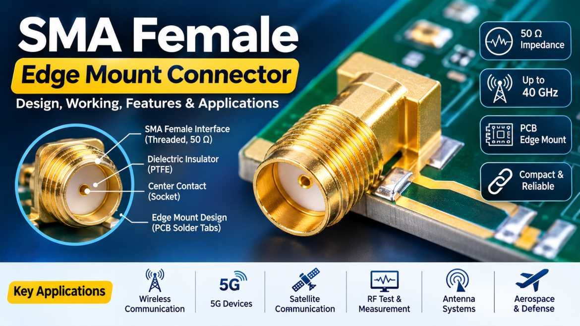
SMA Female Edge Mount Connectors are precision-engineered RF connectors designed to establish reliable electrical connections between coaxial cables and printed circuit boards (PCBs). These connectors are widely used in high-frequency electronic circuits, microwave communication systems, wireless devices, RF testing equipment, antennas, and telecommunications infrastructure.
With the increasing demand for compact electronic devices and high-frequency communication systems, PCB-mounted RF connectors have become essential components in modern electronics. SMA Female Edge Mount Connectors provide a practical solution for connecting coaxial transmission lines directly to PCB edges while maintaining controlled impedance and minimizing signal reflections.
Unlike conventional panel-mounted SMA connectors, edge-mount connectors are specifically designed to be installed along the edge of a PCB. Their center contact connects to the PCB’s RF signal trace, while the surrounding ground contacts are soldered to the PCB ground plane. This configuration creates a compact RF transition between the coaxial interface and the printed circuit board.
SMA Female Edge Mount Connectors are commonly available in 50 Ohm impedance configurations and support a wide range of operating frequencies depending on their design and manufacturing specifications. They are particularly suitable for applications where signal integrity, mechanical stability, compact installation, and reliable high-frequency performance are important.
In this comprehensive guide, we will explore what an SMA Female Edge Mount Connector is, how it works, its construction, features, technical specifications, applications, advantages, and important factors to consider when selecting the right connector.
What Is an SMA Female Edge Mount Connector?
An SMA Female Edge Mount Connector is a miniature coaxial RF connector designed to be mounted directly onto the edge of a printed circuit board. SMA stands for SubMiniature Version A, a threaded coaxial connector interface widely used in radio frequency and microwave applications.
The connector features a female coaxial interface with an internal socket contact that mates with a compatible SMA male connector. On the opposite side, it has PCB mounting contacts that allow direct electrical and mechanical integration with a printed circuit board.
The edge-mount configuration eliminates the need for a separate coaxial cable assembly between the RF connector and the PCB. Instead, the connector provides a direct transition from the coaxial transmission line to the PCB’s RF signal trace.
These connectors are commonly used in:
- RF and microwave circuits
- Wireless communication equipment
- Antenna systems
- 5G communication devices
- RF test and measurement equipment
- Satellite communication systems
- High-frequency PCB assemblies
- Laboratory electronic instruments
- Networking and telecommunications equipment
The combination of a compact design, threaded mating interface, and PCB edge-launch configuration makes SMA Female Edge Mount Connectors a popular choice for precision RF applications.
How Does an SMA Female Edge Mount Connector Work?
An SMA Female Edge Mount Connector works by transferring an RF signal between a coaxial cable and a printed circuit board while maintaining a controlled transmission path.
When an SMA male connector is attached to the female interface, the center contact establishes the electrical connection for the RF signal. The outer conductive body provides the ground connection and shielding around the signal path.
The PCB-side contacts are designed to connect the connector to the corresponding signal and ground structures on the circuit board.
The working process involves the following steps:
- The RF signal enters through the SMA male connector connected to the female interface.
- The center contact transfers the signal toward the PCB signal trace.
- The outer metallic body provides the ground reference.
- Ground tabs or mounting surfaces are soldered to the PCB ground plane.
- The RF signal travels through the PCB transmission line to the connected electronic circuit.
Proper PCB layout and soldering are important because any impedance discontinuity at the connector-to-board transition can cause reflections, insertion loss, and reduced signal performance.
Construction of an SMA Female Edge Mount Connector
An SMA Female Edge Mount Connector consists of several precision-engineered components that work together to provide reliable electrical and mechanical performance.
1. Female Center Contact
The center contact is responsible for transmitting the RF signal through the connector.
It features an internal socket designed to mate with the center pin of a compatible SMA male connector.
Common contact materials include:
- Brass
- Beryllium copper
- Phosphor bronze
The contacts may feature gold plating to improve conductivity, corrosion resistance, and contact reliability.
2. Outer Conductive Body
The outer body forms the external conductive portion of the coaxial interface.
It provides mechanical strength, shielding, and the ground connection required for proper RF signal transmission.
Common materials include:
- Stainless steel
- Brass
- Copper alloys
Nickel or gold plating may be used depending on the connector design and performance requirements.
3. Dielectric Insulator
The dielectric material separates the center contact from the outer conductive body.
It maintains the required electrical insulation and helps establish the connector’s characteristic impedance.
PTFE (Polytetrafluoroethylene) is commonly used because of its excellent dielectric properties, thermal stability, and low dielectric loss.
4. PCB Signal Contact
The PCB signal contact connects the center conductor of the SMA interface to the RF signal trace on the printed circuit board.
Its geometry is carefully designed to minimize impedance discontinuities during the transition from the coaxial structure to the PCB transmission line.
5. Ground Mounting Tabs
Ground tabs or mounting surfaces connect the connector’s outer body to the PCB ground plane.
These contacts provide electrical grounding, mechanical stability, and a low-impedance return path for RF signals.
6. Connector Housing
The housing protects the internal components and provides a threaded interface for mating with compatible SMA male connectors.
Its precision-machined construction helps maintain dimensional accuracy and mechanical durability.
Key Features of SMA Female Edge Mount Connectors
SMA Female Edge Mount Connectors offer several important features that make them suitable for high-frequency applications.
Compact PCB Mounting Design
The edge-mount structure allows direct installation along the PCB edge, reducing the need for additional mounting hardware and cable connections.
50 Ohm Characteristic Impedance
Most SMA Female Edge Mount Connectors are designed for 50 Ohm RF systems, supporting impedance-matched connections in communication and microwave circuits.
High-Frequency Performance
Depending on the connector design, precision SMA edge-launch connectors are available for applications operating up to 18 GHz, 26.5 GHz, and certain specialized versions up to 40 GHz.
Secure Threaded Connection
The threaded SMA interface provides a secure mechanical connection that helps prevent accidental disconnection during operation.
Excellent Signal Integrity
A properly designed connector and PCB launch can minimize insertion loss, signal reflections, and impedance discontinuities.
Reliable Grounding
Multiple ground contacts provide a stable connection between the connector body and the PCB ground plane.
Easy PCB Integration
These connectors can be soldered directly to compatible PCB edge structures, making them suitable for compact electronic assemblies.
Technical Specifications of SMA Female Edge Mount Connectors
The technical specifications of SMA Female Edge Mount Connectors vary according to the manufacturer, design, and intended operating frequency.
The following table provides commonly encountered specification ranges. Actual product datasheets should be consulted before final selection.
| Specification | Typical Details |
|---|---|
| Connector Type | SMA Female Edge Mount |
| Interface | SMA Female |
| Characteristic Impedance | 50 Ohm |
| Mounting Type | PCB Edge Mount |
| Frequency Range | DC to 18 GHz / 26.5 GHz / 40 GHz |
| Center Contact | Gold-Plated Copper Alloy |
| Body Material | Stainless Steel / Brass |
| Insulator Material | PTFE |
| Mating Connector | SMA Male |
| Mounting Method | PCB Solder Mount |
| Operating Temperature | Model Dependent |
| Application | RF & Microwave Systems |
Types of SMA Female Edge Mount Connectors
SMA Female Edge Mount Connectors are available in different designs to accommodate PCB layouts, operating frequencies, and installation requirements.
1. Standard SMA Female Edge Mount Connector
Standard SMA Female Edge Mount Connectors are designed for general-purpose RF applications.
They are commonly used in wireless communication devices, antenna circuits, RF modules, and electronic testing equipment.
Typical features include:
- 50 Ohm impedance
- Female SMA interface
- PCB edge mounting
- Threaded coupling mechanism
- Compact construction
2. High-Frequency SMA Female Edge Mount Connector
High-frequency SMA edge-mount connectors are engineered for applications requiring extended frequency performance and controlled electrical characteristics.
Depending on the design, these connectors may support frequencies up to 26.5 GHz or higher.
They are commonly used in:
- Microwave circuits
- RF measurement equipment
- High-speed communication systems
- Research and development laboratories
3. Precision SMA Female Edge Mount Connector
Precision SMA edge-mount connectors are manufactured with tighter dimensional tolerances to support demanding RF and microwave applications.
They are suitable for applications where low reflection, repeatable performance, and reliable electrical connections are important.
4. Right-Angle SMA Female Edge Mount Connector
Right-angle designs provide an alternative mounting arrangement for compact electronic assemblies.
They are useful when PCB space, connector orientation, or mechanical clearance is limited.
The exact mounting geometry should be checked against the PCB layout before installation.
SMA Female Edge Mount Connector Dimensions
Mechanical dimensions are critical when selecting an SMA Female Edge Mount Connector.
The connector must match the PCB thickness, edge geometry, signal trace position, and available mounting area.
Important dimensions include:
- Overall connector length
- Connector body diameter
- Thread dimensions
- PCB thickness compatibility
- Center contact width
- Ground tab dimensions
- Mounting footprint
- Connector height above PCB
The SMA interface commonly uses a 1/4-36 UNS coupling thread. However, the PCB mounting dimensions and launch geometry vary between manufacturers.
Always refer to the manufacturer’s mechanical drawing before designing the PCB footprint.
SMA Female Edge Mount Connector vs SMA Panel Mount Connector
Both connector types provide an SMA female interface, but their mounting arrangements and applications are different.
| Feature | SMA Female Edge Mount | SMA Female Panel Mount |
|---|---|---|
| Mounting Type | PCB Edge Mount | Panel Mount |
| Installation | Direct PCB Soldering | Equipment Panel |
| PCB Connection | Direct RF Trace | Usually Through Cable or PCB |
| Space Requirement | Compact PCB Edge | Requires Panel Space |
| Mechanical Support | PCB Solder Joints | Panel Mounting Hardware |
| Applications | RF PCB Circuits | RF Equipment Enclosures |
| Installation | PCB Soldering | Panel Fixing |
Applications of SMA Female Edge Mount Connectors
SMA Female Edge Mount Connectors are widely used across different industries where compact RF connectivity and reliable high-frequency performance are required.
1. Wireless Communication Systems
Wireless communication equipment requires reliable connections between RF circuits, antennas, and signal-processing components.
SMA Female Edge Mount Connectors are commonly used in:
- Wireless transceivers
- RF modules
- Communication boards
- Signal amplifiers
- Wireless networking devices
2. 5G Communication Infrastructure
Modern 5G systems use advanced RF circuits operating across different frequency bands.
SMA edge-mount connectors support connections in RF test boards, development platforms, antenna circuits, and communication equipment.
3. Antenna Systems
SMA Female Edge Mount Connectors are used to connect antennas directly to RF printed circuit boards.
Applications include:
- Wi-Fi antennas
- GPS antenna circuits
- Wireless communication modules
- RF evaluation boards
- Embedded antenna systems
4. RF Test and Measurement Equipment
Precision RF connectors are essential for accurate testing and measurement.
SMA Female Edge Mount Connectors are commonly found in:
- Vector network analyzers
- Spectrum analyzers
- Signal generators
- RF evaluation boards
- Microwave test fixtures
5. Satellite Communication
Satellite communication systems use RF and microwave circuits for signal transmission and reception.
SMA edge-mount connectors can be integrated into communication boards, RF modules, and testing equipment used in satellite communication applications.
6. Aerospace and Defense
Aerospace and defense electronics require reliable RF connections in compact and performance-critical systems.
These connectors may be used in:
- Radar development equipment
- RF communication modules
- Navigation systems
- Electronic test assemblies
- Microwave circuit boards
7. IoT and Embedded Electronics
Internet of Things devices require compact wireless communication circuits.
SMA Female Edge Mount Connectors provide an accessible RF interface for embedded systems, wireless modules, and prototype development boards.
8. Research and Development Laboratories
Engineers and researchers use SMA edge-mount connectors to develop and test high-frequency PCB circuits.
They allow direct connection of external RF instruments to the PCB without requiring additional cable assemblies.
Advantages of SMA Female Edge Mount Connectors
SMA Female Edge Mount Connectors offer several advantages for modern RF electronic designs.
- Compact and space-saving design
- Direct PCB integration
- Reliable threaded mating interface
- 50 Ohm impedance compatibility
- Wide frequency availability
- Good signal transmission performance
- Secure mechanical connection
- Excellent grounding capability
- Suitable for microwave applications
- Reduced requirement for additional RF cabling
- Easy integration into RF test boards
- Available in different mounting configurations
Limitations of SMA Female Edge Mount Connectors
Despite their advantages, SMA Female Edge Mount Connectors have certain limitations that should be considered during product selection.
- Require precise PCB edge preparation.
- Incorrect soldering can affect electrical performance.
- PCB thickness must match the connector design.
- Repeated mechanical stress may damage solder joints.
- Maximum operating frequency depends on connector geometry.
- Not all models are suitable for high-power applications.
- Incorrect PCB launch design can increase signal reflections.
- Standard SMA connectors have a lower frequency capability than specialized 2.92 mm or 2.4 mm interfaces.
How to Install an SMA Female Edge Mount Connector on a PCB
Proper installation is essential for achieving reliable electrical performance.
Step 1: Check PCB Compatibility
Verify that the PCB thickness and edge dimensions match the connector’s mechanical specifications.
Step 2: Prepare the PCB Footprint
Design the PCB signal trace and ground pads according to the connector manufacturer’s recommended footprint.
Step 3: Position the Connector
Place the SMA Female Edge Mount Connector along the PCB edge, ensuring that the center contact aligns with the RF signal trace.
Step 4: Solder the Ground Contacts
Solder the connector’s ground tabs to the PCB ground plane to establish a reliable electrical and mechanical connection.
Step 5: Solder the Signal Contact
Connect the center contact to the RF signal trace using the recommended soldering process.
Step 6: Inspect the Connection
Check for solder bridges, incomplete joints, misalignment, and mechanical instability.
Step 7: Perform RF Testing
Use suitable RF test equipment, such as a vector network analyzer, to evaluate return loss, VSWR, and insertion loss across the required frequency range.
Important Factors to Consider When Choosing an SMA Female Edge Mount Connector
Selecting the correct connector is important for maintaining signal integrity and ensuring long-term reliability.
Operating Frequency
Characteristic Impedance
Check the connector’s specified frequency range and ensure that it supports the operating frequency of your RF system.
Most SMA Female Edge Mount Connectors are designed for 50 Ohm systems. Verify impedance compatibility with the PCB and connected RF equipment.
PCB Thickness
Different edge-mount connectors are designed for different PCB thicknesses. Selecting an incompatible model may result in poor mechanical fit and electrical performance.
Connector Material
Check the contact and body materials to ensure suitable conductivity, corrosion resistance, and durability.
Plating
Gold-plated contacts are commonly preferred for reliable electrical connections and corrosion resistance.
VSWR and Return Loss
Evaluate the connector’s RF performance to ensure acceptable signal reflections across the intended frequency range.
Mounting Configuration
Choose the appropriate edge-launch geometry according to the PCB design and available installation space.
Manufacturer Quality
Select connectors manufactured with precision machining, consistent dimensional tolerances, and reliable quality-control processes.
Difference Between SMA Female Edge Mount and SMA Female PCB Mount Connectors
The terms PCB mount and edge mount are sometimes used interchangeably, but they do not always describe the same mounting geometry.
An SMA Female Edge Mount Connector is specifically designed to attach to the edge of a PCB, with its center contact aligned to the board’s RF transmission line.
A general SMA Female PCB Mount Connector may use different configurations, including vertical, surface-mount, or through-hole mounting.
| Feature | SMA Female Edge Mount | SMA Female PCB Mount |
|---|---|---|
| Mounting Position | PCB Edge | PCB Surface or Through-Hole |
| Signal Connection | Edge Launch | Depends on Design |
| Orientation | Usually Horizontal | Horizontal or Vertical |
| Installation | PCB Edge Soldering | Surface or Through-Hole |
| PCB Design | Edge-Launch Footprint | Model-Specific Footprint |
| Common Application | RF Test Boards | RF Electronic Assemblies |
Maintenance and Handling Guidelines
Although SMA Female Edge Mount Connectors are designed for reliable operation, proper handling helps maintain their electrical and mechanical performance.
Follow these recommendations:
- Keep the connector interface clean and free from dust.
- Avoid applying excessive mechanical force during mating.
- Use a calibrated torque wrench when tightening SMA connections.
- Follow the manufacturer’s recommended mating torque.
- Avoid bending or applying stress to the PCB-mounted connector.
- Inspect the center contact for damage.
- Protect unused connectors with suitable dust caps.
- Avoid exceeding the connector’s specified power rating.
- Perform periodic RF measurements in critical applications.
Future Trends in SMA Female Edge Mount Connector Technology
The increasing demand for high-frequency communication and compact electronic devices continues to influence RF connector development.
Modern RF systems require connectors that offer improved electrical performance, smaller footprints, enhanced durability, and consistent impedance characteristics.
Future developments include improved edge-launch geometries, precision-machined contacts, advanced plating materials, better PCB transition designs, and connectors supporting higher microwave frequencies.
With the expansion of 5G, emerging 6G research, satellite communication, aerospace electronics, and high-speed wireless technologies, SMA Female Edge Mount Connectors will continue to play an important role in RF circuit development, testing, and integration.
Conclusion
SMA Female Edge Mount Connectors are essential RF components designed to provide reliable coaxial connections directly to printed circuit boards. Their compact construction, threaded female interface, 50 Ohm impedance, and edge-launch mounting configuration make them suitable for a wide range of RF and microwave applications.
From wireless communication and antenna systems to satellite equipment, RF laboratories, telecommunications infrastructure, and aerospace electronics, these connectors help engineers establish dependable signal connections while maintaining controlled impedance.
Selecting the correct SMA Female Edge Mount Connector requires careful consideration of operating frequency, PCB thickness, mounting dimensions, contact material, plating, return loss, and VSWR specifications.
By choosing a precision-engineered connector and following the recommended PCB layout and installation guidelines, manufacturers can achieve reliable electrical performance and long-term connection stability.
Frequently Asked Questions (FAQs) About SMA Female Edge Mount Connectors
1. What is an SMA Female Edge Mount Connector?
An SMA Female Edge Mount Connector is a coaxial RF connector designed to be soldered directly onto the edge of a printed circuit board. It provides a reliable connection between an external SMA male cable assembly and an RF circuit.
2. What does SMA stand for in an RF connector?
SMA stands for SubMiniature Version A. It is a threaded coaxial connector interface widely used in RF and microwave communication systems.
3. What is the impedance of an SMA Female Edge Mount Connector?
Most SMA Female Edge Mount Connectors have a characteristic impedance of 50 Ohms, making them suitable for standard RF and microwave transmission systems.
4. What frequency range does an SMA Female Edge Mount Connector support?
The frequency range depends on the connector design. Common versions support DC to 18 GHz, while precision and specialized models are available for 26.5 GHz and 40 GHz applications.
5. What is the difference between SMA Male and SMA Female Connectors?
An SMA Male Connector features an external threaded coupling nut and a center pin, whereas an SMA Female Connector has an internal threaded interface and a center socket.
6. How is an SMA Female Edge Mount Connector installed?
It is installed along the edge of a printed circuit board. The center contact is soldered to the RF signal trace, while the ground contacts are connected to the PCB ground plane.
7. What materials are used in SMA Female Edge Mount Connectors?
Common materials include brass, stainless steel, beryllium copper, PTFE, and gold or nickel plating, depending on the connector’s design and specifications.
8. What is the difference between an SMA Edge Mount and a Panel Mount Connector?
An SMA Edge Mount Connector is soldered directly to the edge of a PCB, whereas an SMA Panel Mount Connector is mechanically installed through an equipment enclosure or mounting panel.
9. Are SMA Female Edge Mount Connectors suitable for high-frequency applications?
Yes. They are widely used in RF and microwave circuits. Depending on the model, they can support frequencies up to 18 GHz, 26.5 GHz, or 40 GHz.
10. What PCB thickness is suitable for SMA Female Edge Mount Connectors?
PCB thickness depends on the specific connector design. Common PCB thicknesses include 0.8 mm, 1.0 mm, 1.2 mm, 1.6 mm, and 2.0 mm. Always verify the manufacturer’s mechanical drawing before selection.
11. What is the difference between an SMA Edge Mount and a 2.92 mm Edge Mount Connector?
Both connectors are used in RF and microwave applications, but their interfaces and frequency capabilities differ. Standard SMA connectors generally support frequencies up to 18 GHz, while precision 2.92 mm connectors can support frequencies up to 40 GHz. Their mating interfaces should not be treated as interchangeable without checking compatibility.
12. Where are SMA Female Edge Mount Connectors commonly used?
They are commonly used in wireless communication devices, RF test equipment, antenna circuits, 5G development boards, satellite communication systems, microwave circuits, and aerospace electronics.