RG405 coaxial cable is a high-performance, semi-rigid RF coaxial cable designed for reliable transmission of radio frequency and microwave signals. It is widely used in applications where stable impedance, excellent shielding, low signal loss, and precise electrical performance are required. Unlike flexible coaxial cables that use braided outer conductors, RG405 typically uses a solid outer conductor, giving it excellent shielding effectiveness and mechanical stability.
RG405 coaxial cable is particularly popular in RF and microwave assemblies, laboratory test equipment, telecommunications systems, aerospace electronics, defense equipment, radar systems, wireless communication equipment, and other high-frequency applications. Its compact construction also makes it suitable for applications where installation space is limited and electrical performance must remain highly predictable.
The cable is commonly associated with a 50-ohm RF transmission system and is frequently terminated with precision connectors such as SMA, 2.92 mm, 2.4 mm, SMP, and other high-frequency interfaces. Depending on the exact manufacturer, construction, and assembly, RG405 cable can support microwave frequencies extending into the tens of gigahertz.
Understanding the construction, electrical characteristics, advantages, limitations, and applications of RG405 coaxial cable is important when selecting an RF cable for a high-frequency system.
What Is RG405 Coaxial Cable?
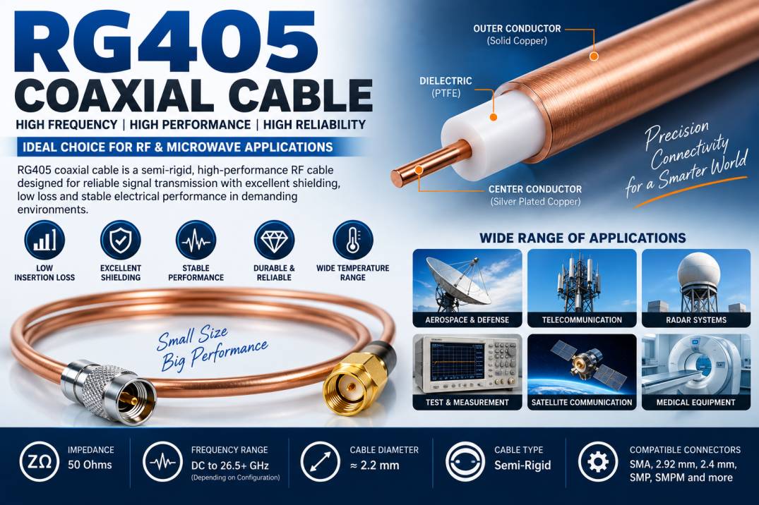
RG405 is a small-diameter semi-rigid coaxial cable designed for high-frequency RF and microwave signal transmission. It consists of a center conductor, dielectric insulation, and solid metallic outer conductor.
The solid outer conductor provides excellent electromagnetic shielding and helps maintain a consistent transmission environment around the center conductor. Because the cable is semi-rigid, it can be formed into a specific shape during installation and generally retains that shape.
RG405 coaxial cable is commonly selected when engineers need a compact RF cable with stable impedance, strong shielding, and predictable performance.
The cable is particularly useful for internal RF connections, test equipment, communication modules, microwave assemblies, and electronic systems where conventional flexible coaxial cable may not provide sufficient mechanical or electrical stability.
How Does RG405 Coaxial Cable Work?
RG405 coaxial cable transmits RF energy through its center conductor while the surrounding dielectric maintains the required spacing between the center conductor and outer conductor.
The outer conductor serves two important purposes. First, it provides the return path for the RF circuit. Second, it acts as a shield that reduces electromagnetic interference and prevents RF energy from escaping the cable.
The coaxial structure helps maintain a controlled characteristic impedance along the transmission path. When the cable, connectors, and equipment are properly matched, signal reflections are minimized and efficient RF power transfer is achieved.
At high frequencies, cable geometry becomes extremely important. Small changes in conductor dimensions, dielectric properties, connector construction, or cable bending can affect impedance, insertion loss, return loss, and phase characteristics. This is why precision manufacturing is particularly important for RG405 microwave cable assemblies.
Construction of RG405 Coaxial Cable
RG405 coaxial cable contains several important layers that work together to provide high-frequency performance.
Center Conductor
The center conductor carries the RF signal.
Depending on the manufacturer and cable construction, the conductor may be manufactured from copper or copper-based material and may use plating such as silver plating to improve high-frequency conductivity and solderability.
A high-quality center conductor helps reduce conductor loss and supports stable RF transmission.
Dielectric
The dielectric material separates the center conductor from the outer conductor.
PTFE and related low-loss dielectric materials are commonly associated with semi-rigid microwave cable constructions because they provide good electrical insulation, low dielectric loss, and suitable thermal performance.
The dielectric also determines important characteristics such as:
- Characteristic impedance
- Velocity factor
- Capacitance
- Dielectric loss
- Frequency response
Outer Conductor
One of the defining features of semi-rigid RG405 cable is its solid metallic outer conductor.
The outer conductor can provide substantially better shielding than a conventional braided shield. This makes the cable particularly useful in environments where electromagnetic interference must be minimized.
The solid outer conductor also contributes to the mechanical stability of the cable.
RG405 Coaxial Cable Specifications
Exact specifications vary by manufacturer and construction, so the manufacturer’s datasheet should always be checked before specifying the cable for a critical RF application.
| Parameter | Typical RG405 Characteristics |
|---|---|
| Cable Type | Semi-Rigid Coaxial Cable |
| Characteristic Impedance | 50 Ohms |
| Construction | Coaxial |
| Outer Conductor | Solid Metal |
| Dielectric | Low-Loss PTFE Type |
| Cable Diameter | Approximately 2.2 mm |
| Application Frequency | RF and Microwave |
| Shielding | Excellent |
| Installation | Formable / Semi-Rigid |
| Connector Options | SMA, 2.92 mm, 2.4 mm, SMP and others |
| Primary Applications | RF, Microwave, Aerospace, Defense, Testing |
These values are representative rather than universal. RG405 cable from different manufacturers can have different attenuation, temperature, power-handling, and maximum-frequency specifications.
What Is the Impedance of RG405 Coaxial Cable?
RG405 coaxial cable is commonly used as a 50-ohm coaxial cable.
A 50-ohm impedance is standard across many RF and microwave systems, including:
- Wireless communication
- RF test equipment
- Radar
- Aerospace electronics
- Defense systems
- Satellite communication
- Antenna systems
- Microwave circuits
Maintaining a consistent 50-ohm transmission path is essential for reducing reflections and achieving predictable RF performance.
Frequency Range of RG405 Cable
The usable frequency range of RG405 depends on the specific cable construction, manufacturer, connector type, assembly technique, and required performance criteria.
RG405 is generally used for high-frequency RF and microwave applications, with many assemblies designed for operation into the tens of gigahertz.
Typical applications can include frequency ranges such as:
- DC to 6 GHz
- DC to 12 GHz
- DC to 18 GHz
- DC to 26.5 GHz
- Higher-frequency applications depending on construction and connectors
For applications above approximately 18 GHz, engineers should evaluate the complete cable assembly rather than considering the cable alone. Connector quality, termination technique, bending, and installation geometry can have a significant effect on performance.
RG405 Cable Diameter
RG405 is a compact coaxial cable, typically around 2.2 mm in outside diameter depending on the applicable standard and manufacturer.
Its relatively small diameter provides several advantages:
- Space-saving installation
- Reduced weight
- Easy routing in compact equipment
- Suitable for dense RF assemblies
- Useful for multi-channel systems
The small diameter makes RG405 particularly useful for internal equipment connections where larger coaxial cables would be difficult to install.
Key Electrical Characteristics of RG405
Insertion Loss
Insertion loss represents the amount of signal power lost as an RF signal travels through the cable.
Lower insertion loss is generally preferred, particularly in high-frequency systems where even small losses can affect the available signal power.
The actual insertion loss of RG405 depends on frequency and cable length.
Return Loss
Return loss indicates how much RF energy is reflected toward the source because of impedance discontinuities.
Higher return loss generally indicates better impedance matching.
Connector quality and cable termination have a major influence on the return loss of a completed RG405 cable assembly.
VSWR
Voltage Standing Wave Ratio, or VSWR, is another important measurement of impedance matching.
A lower VSWR indicates that less RF energy is being reflected.
For precision microwave assemblies, engineers typically evaluate the VSWR of the complete cable assembly rather than relying only on the cable specification.
Shielding Effectiveness
RG405’s solid outer conductor provides excellent shielding.
This makes it useful in environments where external electromagnetic interference can affect sensitive RF signals.
Strong shielding is especially valuable in:
- RF laboratories
- Medical electronics
- Radar systems
- Defense electronics
- Communication equipment
- High-density electronic systems
RG405 Semi-Rigid Cable vs Flexible Coaxial Cable
| Feature | RG405 Semi-Rigid Cable | Flexible Coaxial Cable |
|---|---|---|
| Outer Conductor | Solid metal | Usually braided |
| Flexibility | Limited | High |
| Shielding | Excellent | Good to excellent |
| Shape Retention | Yes | No |
| Mechanical Stability | High | Moderate |
| RF Stability | Excellent | Depends on construction |
| Repeated Movement | Not recommended | Better suited |
| Compact RF Assemblies | Excellent | Good |
| Microwave Applications | Excellent | Application dependent |
| Installation | Formed during assembly | Easier to route |
The major difference is the outer conductor. Flexible cables use a braid or similar flexible shield, while semi-rigid cables use a solid metallic tube.
Advantages of RG405 Coaxial Cable
RG405 offers several advantages for demanding RF applications.
Excellent Shielding
The solid outer conductor provides strong protection against electromagnetic interference and reduces unwanted RF leakage.
Compact Construction
Its small diameter allows engineers to install multiple RF cables in limited spaces.
Stable Electrical Performance
The controlled coaxial geometry supports predictable impedance and RF characteristics.
High-Frequency Capability
RG405 is designed for RF and microwave applications where ordinary low-frequency cables may not provide adequate performance.
Mechanical Stability
Once formed, semi-rigid cable can retain its installed shape, helping prevent unintended movement.
Low Signal Loss
When correctly selected for frequency and length, RG405 can provide efficient signal transmission.
Excellent Phase Stability
The controlled construction of semi-rigid cable can provide stable phase characteristics, which is valuable in precision RF systems.
Reliable Long-Term Performance
Because the cable does not rely on a flexible braided shield, it can provide excellent mechanical and electrical stability in fixed installations.
Applications of RG405 Coaxial Cable
Aerospace and Defense
RG405 cable is commonly used in aerospace and defense electronics where compact, reliable, high-frequency connections are required.
Applications may include:
- Radar systems
- Avionics
- Electronic warfare equipment
- Communication systems
- Navigation systems
- RF instrumentation
RF Test and Measurement
Laboratories use semi-rigid RF cable assemblies to connect:
- Vector network analyzers
- Spectrum analyzers
- Signal generators
- Power meters
- RF sources
- Microwave test fixtures
The controlled construction of RG405 helps maintain predictable measurement performance.
Telecommunications
RG405 can be used for internal RF connections in:
- Base station equipment
- Wireless communication systems
- RF modules
- Signal processing equipment
- Radio equipment
Satellite Communication
Satellite communication equipment requires high-performance RF interconnections. RG405 can be used in compact RF assemblies inside satellite and ground-based communication equipment.
Medical Electronics
Specialized medical equipment can require controlled RF signal transmission. Semi-rigid cable can be useful where electromagnetic shielding and stable performance are important.
Radar Systems
Radar systems operate at high frequencies and often require compact, precisely routed RF connections. RG405 is suitable for various internal microwave interconnection applications.
Industrial Electronics
Industrial RF systems, sensors, wireless equipment, and automation systems can use semi-rigid cable assemblies for reliable signal transmission.
Common Connectors Used With RG405
RG405 cable can be terminated with a variety of RF connectors depending on the frequency and equipment interface.
Common options include:
SMA Connector
SMA connectors are among the most widely used connectors for RG405 cable assemblies. They are popular in RF modules, laboratory equipment, antennas, wireless systems, and microwave equipment.
2.92 mm Connector
2.92 mm connectors are designed for higher-frequency microwave applications and are often used where precision performance is required.
2.4 mm Connector
2.4 mm connectors are commonly selected for high-frequency microwave and millimeter-wave applications.
1.85 mm Connector
1.85 mm connectors are used in very-high-frequency measurement and microwave systems.
SMP Connector
SMP connectors are compact push-on RF connectors suitable for dense electronic assemblies.
SMPM Connector
SMPM connectors provide an even smaller interface for high-density RF and microwave applications.
RG405 Cable Assembly
An RG405 cable assembly consists of the cable terminated with one or more RF connectors.
Examples include:
- SMA Male to SMA Male RG405 Cable
- SMA Male to SMA Female RG405 Cable
- SMA Female to SMA Female RG405 Cable
- SMA Male to 2.92 mm Cable
- 2.92 mm Male to 2.92 mm Cable
- SMP Male to SMA Male Cable
- SMPM to SMPM Cable
Custom cable assemblies can be manufactured according to required length, connector combination, bend configuration, and electrical specifications.
Why Connector Selection Matters
The performance of an RG405 cable assembly depends not only on the cable but also on the connectors and termination process.
At microwave frequencies, a poorly designed connector transition can introduce:
- Impedance discontinuity
- Additional insertion loss
- Higher VSWR
- Increased return loss
- Unwanted reflections
For this reason, high-frequency RG405 assemblies should be manufactured using appropriate precision connectors and controlled termination processes.
How to Choose the Right RG405 Coaxial Cable
Selecting RG405 requires evaluating the complete application rather than simply choosing a cable based on its name.
Consider Operating Frequency
First determine the highest frequency the cable must support.
A cable suitable for 6 GHz may not deliver the same performance at 26.5 GHz.
Consider Cable Length
Signal attenuation increases with cable length. For high-frequency systems, keep the cable as short as practical when low loss is important.
Check Impedance
For most RG405 RF applications, a 50-ohm system is required.
Select the Correct Connector
The connector should match the equipment interface and support the required operating frequency.
Evaluate VSWR
Choose an assembly with suitable VSWR for the application.
Check Insertion Loss
Compare attenuation specifications at the actual operating frequencies rather than relying only on a single nominal value.
Consider Temperature
For aerospace, defense, industrial, and outdoor applications, verify the cable’s operating temperature range.
Consider Mechanical Requirements
Semi-rigid cable is ideal for fixed installations but should not normally be selected for applications involving continuous flexing.
RG405 Cable Bending and Installation
One of the most important considerations when installing RG405 is proper forming.
Semi-rigid cable is designed to be shaped during installation. However, excessive bending or repeated re-forming can affect its geometry and electrical performance.
Incorrect bending may cause:
- Impedance variation
- Increased insertion loss
- Higher VSWR
- Mechanical damage
- Connector stress
Specialized bending tools are recommended when precision cable assemblies are required.
RG405 Cable vs RG316 Cable
| Feature | RG405 | RG316 |
|---|---|---|
| Cable Type | Semi-Rigid | Flexible |
| Outer Conductor | Solid Metal | Braided Shield |
| Diameter | Approximately 2.2 mm | Approximately 2.5 mm |
| Flexibility | Low | High |
| Shielding | Excellent | Good |
| Shape Retention | Yes | No |
| Movement | Not recommended | Better |
| Typical Use | Microwave Assemblies | Flexible RF Connections |
| Installation | Formed | Routed |
RG405 is generally preferred when mechanical stability and shielding are more important than flexibility. RG316 is more suitable where the cable must be routed around moving or closely spaced components.
RG405 Cable vs RG402 Cable
RG402 is another popular semi-rigid RF cable used in microwave systems.
| Feature | RG405 | RG402 |
|---|---|---|
| Approx. Diameter | 2.2 mm | 3.6 mm |
| Construction | Semi-Rigid | Semi-Rigid |
| Flexibility | Higher than RG402 | Lower |
| Space Requirement | Lower | Higher |
| Power Capability | Application dependent | Generally higher due to larger size |
| Typical Use | Compact RF Assemblies | Higher-Power Microwave Assemblies |
The choice depends on frequency, power, installation space, attenuation, and mechanical requirements.
Maintenance of RG405 Coaxial Cable
RG405 cable assemblies require relatively little maintenance when correctly installed.
Recommended practices include:
- Avoid repeated bending.
- Do not twist the cable near connectors.
- Protect connectors from contamination.
- Use appropriate torque when installing threaded RF connectors.
- Avoid excessive mechanical stress.
- Inspect connectors for damage.
- Keep unused connectors properly protected.
- Avoid exceeding rated power or temperature limits.
Quality Considerations for RG405 Cable
When purchasing RG405 coaxial cable or a finished RG405 cable assembly, consider:
- Cable construction
- Conductor material
- Dielectric material
- Outer conductor material
- Characteristic impedance
- Frequency range
- Insertion loss
- VSWR
- Return loss
- Shielding effectiveness
- Connector quality
- Termination quality
- Temperature rating
- Cable length
- Manufacturer specifications
For critical applications, request a test report or electrical performance data for the complete cable assembly.
Future of RG405 Coaxial Cable
The demand for compact high-frequency interconnect solutions is expected to remain strong as communication and electronic systems move toward higher frequencies.
Technologies such as:
- 5G
- 6G
- Satellite internet
- Millimeter-wave communication
- Advanced radar
- Autonomous vehicles
- Aerospace electronics
- High-speed test equipment
require RF interconnections capable of maintaining stable performance at increasingly high frequencies.
RG405 and similar semi-rigid cable technologies will continue to be valuable for compact microwave assemblies, especially where shielding, phase stability, and mechanical reliability are critical.
Conclusion
RG405 coaxial cable is a compact, high-performance semi-rigid RF cable designed for demanding radio frequency and microwave applications. Its controlled coaxial construction, solid metallic outer conductor, excellent shielding, stable impedance, and compact diameter make it an effective solution for precision RF interconnections.
It is widely suitable for aerospace, defense, telecommunications, radar, satellite communication, medical electronics, industrial systems, and RF test and measurement equipment.
When selecting RG405 coaxial cable, engineers should consider operating frequency, cable length, impedance, insertion loss, VSWR, connector type, temperature range, power requirements, and mechanical installation conditions. For high-frequency applications, the complete cable assembly—including connectors and termination—should be evaluated rather than the cable alone.
Frequently Asked Questions About RG405 Coaxial Cable
1. What is RG405 coaxial cable?
RG405 is a compact semi-rigid coaxial cable designed for RF and microwave signal transmission. It typically uses a solid metallic outer conductor and is commonly used in 50-ohm RF systems.
2. Is RG405 cable 50 Ohm?
Yes. RG405 is commonly specified as a 50-ohm coaxial cable, making it suitable for many RF and microwave communication and test applications.
3. What is the diameter of RG405 cable?
RG405 is generally around 2.2 mm in outside diameter, although exact dimensions can vary according to the applicable specification and manufacturer.
4. What frequency can RG405 cable support?
The frequency capability depends on the cable construction and complete assembly. RG405 is commonly used for RF and microwave applications extending into the tens of gigahertz.
5. Is RG405 flexible?
RG405 is classified as semi-rigid rather than fully flexible. It can be formed into a required shape during installation but is not intended for continuous flexing.
6. What is the difference between RG405 and RG316?
RG405 is a semi-rigid cable with a solid outer conductor, while RG316 is a flexible coaxial cable with a braided outer shield. RG405 generally provides better shielding and mechanical stability, while RG316 offers greater flexibility.
7. What connectors can be used with RG405?
RG405 cable assemblies can be terminated with SMA, 2.92 mm, 2.4 mm, 1.85 mm, SMP, SMPM, and other compatible RF connectors.
8. Where is RG405 coaxial cable used?
RG405 is used in aerospace, defense, radar, telecommunications, satellite communication, RF test equipment, medical electronics, industrial systems, and microwave assemblies.
9. Can RG405 be used for high-frequency applications?
Yes. RG405 is specifically designed for RF and microwave applications. The maximum usable frequency should be verified from the manufacturer’s cable and connector specifications.
10. What are the advantages of RG405 cable?
Major advantages include excellent shielding, compact size, stable impedance, good microwave performance, mechanical stability, low signal loss, and reliable long-term performance.
11. Can RG405 cable be customized?
Yes. RG405 cable assemblies can be customized by cable length, connector type, connector orientation, bend configuration, and other application-specific requirements.
12. What should I consider when buying RG405 cable?
Consider impedance, operating frequency, insertion loss, VSWR, cable length, connector type, power handling, temperature rating, shielding, bend requirements, and the quality of the finished cable assembly.