Corrugated RF cable is a specialized coaxial cable designed to transmit high-frequency radio frequency signals with low signal loss, excellent shielding, mechanical flexibility, and long-term environmental reliability. It is widely used in telecommunications, 4G and 5G networks, base stations, distributed antenna systems, RF transmission systems, broadcasting, radar, satellite communication, and other high-performance wireless applications.
Unlike conventional coaxial cables with a smooth outer conductor, corrugated RF cables use a mechanically formed corrugated outer conductor. The corrugation provides additional flexibility while maintaining excellent electrical shielding and mechanical strength.
Corrugated coaxial cable is particularly valuable in applications where the cable must be routed through towers, equipment rooms, antenna systems, rooftops, tunnels, and other locations where bending and installation flexibility are important.
For telecom infrastructure, the correct selection of corrugated RF cable can directly affect insertion loss, return loss, VSWR, PIM performance, installation reliability, and overall network performance.
What Is Corrugated RF Cable?
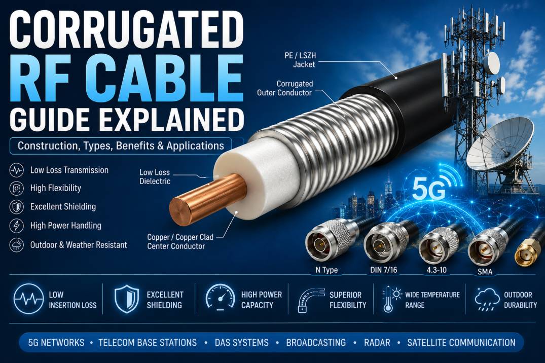
A corrugated RF cable is a type of coaxial transmission line consisting primarily of a center conductor, dielectric material, outer conductor, and protective jacket.
The outer conductor is manufactured with a corrugated profile rather than a completely smooth cylindrical surface. These corrugations allow the cable to bend more easily without significantly compromising its RF performance.
The basic structure can be represented as:
Center Conductor → Dielectric → Corrugated Outer Conductor → Protective Jacket
Depending on the design, corrugated RF cables may use copper, copper-clad materials, aluminum, or other conductive materials for the conductors. The dielectric is typically selected to provide controlled impedance, low dielectric loss, and stable performance over the intended operating frequency and temperature range.
How Does Corrugated RF Cable Work?
Corrugated RF cable works on the same fundamental principle as other coaxial transmission lines.
The RF signal travels through the center conductor while the outer conductor provides the return path and electromagnetic shielding. The dielectric material separates the two conductors and helps maintain the required characteristic impedance.
The outer conductor prevents unwanted electromagnetic radiation from escaping the cable and reduces interference from external electromagnetic fields.
The corrugated construction adds mechanical flexibility. Instead of forcing a rigid smooth conductor to bend, the corrugations allow controlled deformation along the cable length.
This combination gives corrugated RF cable an important balance between:
Low RF loss
High shielding effectiveness
Mechanical flexibility
High power handling
Environmental durability
Reliable long-distance RF transmission
Construction of Corrugated RF Cable
A corrugated RF cable generally contains four major layers.
1. Center Conductor
The center conductor carries the RF signal. It is commonly manufactured from highly conductive materials such as copper or copper-clad copper.
The conductor size and material influence several cable characteristics, including:
Insertion loss
Power handling
DC resistance
Frequency performance
Temperature rise
Mechanical flexibility
A larger conductor can generally support lower resistance and improved power-handling capability, although cable diameter, flexibility, and manufacturing requirements must also be considered.
2. Dielectric
The dielectric surrounds the center conductor and separates it from the outer conductor.
Common dielectric materials include polyethylene, foam polyethylene, and PTFE-based materials depending on the cable design and frequency requirements.
The dielectric affects:
Characteristic impedance
Velocity factor
Insertion loss
Temperature stability
Signal propagation
Mechanical dimensions
For telecom RF cables, low-density foam dielectric materials are often used to reduce dielectric losses and achieve lower attenuation.
3. Corrugated Outer Conductor
The corrugated outer conductor is the defining feature of this cable type.
Instead of using a completely smooth conductive tube, the conductor is formed into a series of controlled corrugations.
This construction provides mechanical flexibility and allows the cable to tolerate bending during installation.
The outer conductor also performs the critical electrical function of shielding the RF signal from external electromagnetic interference.
4. Protective Jacket
The outer jacket protects the cable against environmental and mechanical conditions.
Depending on the application, jackets may be designed to withstand:
UV radiation
Moisture
Rain
Temperature variations
Abrasion
Chemicals
Outdoor installation conditions
Fire-related requirements
The jacket material should always be selected according to the installation environment and applicable standards.
Why Is the Outer Conductor Corrugated?
The primary reason for corrugating the outer conductor is to increase flexibility.
A smooth metallic tube provides excellent electrical shielding but can be relatively difficult to bend. Corrugation introduces controlled mechanical flexibility into the conductor.
This makes the cable easier to route around:
Antenna mounts
Tower structures
Cable trays
Equipment racks
Roof penetrations
Telecom cabinets
RF equipment
The corrugated structure can also reduce mechanical stress during installation when the cable needs to follow a curved path.
Key Characteristics of Corrugated RF Cable
Corrugated RF cables are selected for applications requiring a combination of electrical and mechanical performance.
Important characteristics include:
Low insertion loss
Low VSWR
Excellent return loss
High shielding effectiveness
High power handling
Controlled characteristic impedance
Good phase stability
Mechanical flexibility
Outdoor durability
Low PIM options
Wide frequency coverage
Long service life
The exact performance depends on cable construction, diameter, connectorization, operating frequency, installation method, and manufacturer specifications.
Types of Corrugated RF Cable
Corrugated RF cables are available in several configurations based on conductor construction and application requirements.
Flexible Corrugated RF Cable
Flexible corrugated cables are designed for applications requiring relatively frequent routing, bending, or installation around equipment.
They are commonly used for antenna feeder connections and RF equipment interconnections.
Semi-Flexible Corrugated RF Cable
Semi-flexible versions provide a balance between mechanical flexibility and structural stability.
They are commonly used in fixed installations where the cable needs to be bent during installation but does not require continuous movement.
Helically Corrugated RF Cable
Helically corrugated cables use a spiral-shaped corrugation around the outer conductor.
This design can provide enhanced flexibility and is widely used in larger RF feeder systems.
Annularly Corrugated RF Cable
Annularly corrugated cables feature ring-shaped corrugations around the cable circumference.
They are designed to provide controlled flexibility while maintaining consistent RF characteristics.
Foam Dielectric Corrugated RF Cable
Foam dielectric construction is widely used where low attenuation is a priority.
The reduced dielectric density helps decrease dielectric losses and can make the cable suitable for long RF transmission paths.
Common Corrugated RF Cable Sizes
Corrugated RF cables are available in different diameters. Cable diameter has a major impact on attenuation, power handling, flexibility, and installation requirements.
Common telecom feeder sizes include:
1/4 inch
3/8 inch
1/2 inch
5/8 inch
7/8 inch
1-1/4 inch
1-5/8 inch
Larger feeder cables may be used for specialized high-power RF systems.
The correct size should be selected based on frequency, cable length, required attenuation, power level, installation space, bend radius, and connector compatibility.
Corrugated RF Cable vs Smooth-Wall Coaxial Cable
The major difference is the construction of the outer conductor.
A smooth-wall coaxial cable uses a continuous smooth metallic outer conductor, while corrugated cable uses a formed corrugated conductor.
Corrugated construction generally provides better installation flexibility, particularly for large-diameter feeder cables.
Smooth-wall designs can offer excellent mechanical rigidity and shielding but may require greater care during bending.
The best option depends on the application, installation requirements, frequency, power, cable length, and environmental conditions.
Advantages of Corrugated RF Cable
Excellent Flexibility
The corrugated outer conductor allows the cable to bend more easily than many rigid feeder constructions.
Low RF Loss
Properly designed corrugated feeder cables can provide low attenuation, making them suitable for long transmission paths.
High Shielding Effectiveness
The metallic outer conductor provides strong electromagnetic shielding and helps minimize unwanted radiation and interference.
High Power Capability
Large-diameter corrugated cables can support high RF power levels, making them suitable for cellular base stations and broadcast systems.
Excellent Mechanical Reliability
The corrugated structure provides flexibility while maintaining the structural integrity required for fixed RF installations.
Outdoor Suitability
With an appropriate protective jacket, corrugated RF cables can be used in demanding outdoor telecom environments.
Easy Installation
Their flexibility can simplify routing around tower structures, antenna systems, and equipment installations.
Corrugated RF Cable Specifications
When selecting a corrugated RF cable, engineers should evaluate the following specifications.
Characteristic Impedance
Most telecom RF systems use 50-ohm impedance.
Maintaining consistent impedance is essential for minimizing signal reflections.
Frequency Range
The cable must support the required operating frequency.
Modern applications can range from traditional cellular frequencies to higher-frequency microwave and RF systems.
Insertion Loss
Insertion loss indicates how much signal power is lost as the RF signal travels through the cable.
Lower attenuation is generally desirable, especially for long cable runs.
VSWR
Voltage Standing Wave Ratio indicates the degree of impedance mismatch in the RF transmission system.
Lower VSWR generally indicates better matching.
Return Loss
Return loss describes the amount of reflected signal caused by impedance discontinuities.
Higher return loss generally represents better impedance matching.
Maximum Power
The cable must be capable of safely handling the RF power transmitted through it.
Power capacity can depend on frequency, cable diameter, ambient temperature, installation conditions, and connector configuration.
Minimum Bend Radius
The minimum bend radius defines how tightly the cable can be bent without compromising performance or damaging the cable.
This specification is particularly important during tower and antenna installation.
Operating Temperature
Outdoor RF feeder cables may experience significant temperature changes.
The cable should therefore be selected according to the expected minimum and maximum operating temperatures.
Corrugated RF Cable Connectors
Corrugated cables require properly matched RF connectors to maintain the performance of the complete transmission system.
Common connector types used with RF feeder cables include:
N Type
DIN 7/16
4.3-10
SMA
TNC
Other specialized feeder connectors
The connector must match the cable diameter, impedance, frequency range, power requirements, and installation method.
Connector installation quality is extremely important because an incorrectly installed connector can introduce significant VSWR, insertion loss, PIM, and reliability problems.
Low PIM Corrugated RF Cable
Passive Intermodulation, commonly known as PIM, is an important consideration in cellular and wireless infrastructure.
PIM occurs when two or more RF signals interact with nonlinear components and generate unwanted frequencies.
Corrugated RF cable systems designed for low-PIM applications typically use carefully controlled materials, manufacturing processes, and connector interfaces.
Low-PIM performance is particularly important in:
4G networks
5G networks
Distributed antenna systems
Indoor coverage systems
High-density cellular sites
Public safety communication systems
RF test environments
A low-PIM cable alone does not guarantee low system PIM. Connectors, adapters, antennas, installation practices, corrosion, mechanical joints, and contamination can all influence overall PIM performance.
Applications of Corrugated RF Cable
5G Base Stations
Corrugated feeder cables are used to connect RF equipment and antennas in wireless infrastructure.
4G LTE Networks
They remain widely used in cellular network installations where reliable RF signal transmission is required.
Distributed Antenna Systems
DAS networks use RF feeder cables to distribute wireless signals throughout buildings, campuses, transportation facilities, and large public spaces.
Telecom Towers
Tower installations require cables that can withstand outdoor environments while remaining manageable during installation.
Broadcasting
RF feeder cables are used in radio and television transmission systems to connect transmitters to antennas.
Radar Systems
Radar equipment requires reliable high-frequency signal transmission with controlled impedance and low loss.
Satellite Communication
Corrugated coaxial cable can be used in RF and microwave signal distribution systems associated with satellite communication infrastructure.
Industrial RF Systems
Industrial communication, monitoring, testing, and automation systems may also use corrugated RF cables.
Corrugated RF Cable in 5G Infrastructure
5G networks require RF transmission systems capable of supporting multiple frequency bands, higher data capacity, and increasingly complex antenna configurations.
Corrugated RF feeder cables can be used in suitable 5G infrastructure where low attenuation, mechanical flexibility, shielding, and reliable outdoor performance are required.
In high-density installations, cable selection should consider:
Operating frequency
Cable attenuation
PIM performance
Connector type
Power handling
Bending requirements
Cable routing
Weather protection
Installation space
Future network expansion
How to Install Corrugated RF Cable
Correct installation is essential for maintaining cable performance.
Step 1: Plan the Cable Route
Determine the shortest practical route while respecting minimum bend radius and mechanical installation requirements.
Step 2: Select Compatible Connectors
Use connectors specifically designed for the cable diameter and construction.
Step 3: Prepare the Cable Correctly
Cable preparation should follow the connector manufacturer’s recommended dimensions and tooling requirements.
Step 4: Install the Connector
The connector should be installed using appropriate tools and procedures.
Step 5: Control the Bend Radius
Avoid sharp bends or excessive mechanical force.
Step 6: Secure the Cable
Use suitable cable clamps and supports to prevent unnecessary movement, vibration, or mechanical stress.
Step 7: Weatherproof Outdoor Connections
Outdoor RF connections should be properly sealed against moisture and environmental exposure.
Step 8: Test the Installation
Depending on the application, technicians may verify:
VSWR
Return loss
Insertion loss
PIM
Continuity
Insulation
Cable distance
RF performance
Common Installation Mistakes
Several installation mistakes can negatively affect RF performance.
Excessive Bending
Bending beyond the recommended radius can deform the cable and affect impedance.
Incorrect Connector Installation
Improper connector preparation can produce high VSWR and poor return loss.
Poor Weatherproofing
Moisture penetration can cause corrosion and long-term performance degradation.
Improper Cable Support
Insufficient support can place mechanical stress on connectors and cable sections.
Excessive Pulling Force
Strong pulling forces can damage the conductor or dielectric.
Contaminated RF Interfaces
Dust, moisture, oil, and other contaminants can negatively affect RF connector performance.
Incorrect Torque
RF connectors should be tightened according to the manufacturer’s specified torque requirements.
How to Choose the Right Corrugated RF Cable
Selecting the correct cable requires more than simply choosing a diameter.
First, identify the operating frequency and required impedance.
Next, determine the cable length and calculate the acceptable attenuation.
Then evaluate power-handling requirements.
After that, consider installation conditions, including bend radius, temperature, UV exposure, moisture, and mechanical stress.
Finally, select compatible connectors and verify the complete RF assembly.
Important selection parameters include:
Frequency range
Characteristic impedance
Cable diameter
Attenuation
VSWR
Return loss
PIM performance
Power rating
Bend radius
Operating temperature
Jacket material
Connector type
Cable length
Environmental requirements
Corrugated RF Cable Maintenance
Proper maintenance can extend the service life of an RF feeder system.
Inspect cables periodically for:
Jacket damage
Cracks
Corrosion
Loose connectors
Water ingress
Improper bends
Damaged clamps
Connector contamination
Physical deformation
RF performance should also be tested when a network experiences unexpected signal degradation.
Corrugated RF Cable Testing
Professional RF installations may require several tests.
VSWR Test
Used to identify impedance mismatch and reflections.
Insertion Loss Test
Used to measure signal loss through the cable assembly.
PIM Test
Particularly important in modern cellular infrastructure.
Return Loss Test
Used to assess the quality of impedance matching.
Time Domain Reflectometry
TDR can help identify cable faults, discontinuities, connector problems, or damaged sections.
Continuity Testing
Used to verify electrical continuity of the cable assembly.
Corrugated RF Cable Standards
Depending on the application and market, RF feeder cables may be designed and tested according to applicable industry, telecommunications, electrical, environmental, and mechanical standards.
When purchasing cable for a professional telecom project, engineers should request manufacturer datasheets, test reports, material information, and applicable compliance documentation.
Standards and qualification requirements can vary according to the specific application and customer specification, so the latest applicable requirements should always be confirmed before procurement.
Corrugated RF Cable vs RF Cable Assembly
A corrugated RF cable refers primarily to the cable itself.
An RF cable assembly normally consists of a cable terminated with connectors on one or both ends.
For example:
Corrugated RF Cable + N Type Connector + N Type Connector = N Type RF Cable Assembly
The finished assembly must be evaluated as a complete RF transmission component because connector performance can significantly influence the electrical characteristics of the cable system.
Why Quality Matters in Corrugated RF Cable
A poor-quality RF feeder can create signal loss, reflections, PIM issues, mechanical failures, and maintenance problems.
High-quality corrugated RF cable should have:
Consistent impedance
Controlled dimensions
Reliable conductor materials
Stable dielectric construction
Uniform corrugation
Reliable shielding
Strong environmental protection
Consistent attenuation
Reliable connector compatibility
Manufacturing quality control
For mission-critical telecom and RF systems, cable quality should be evaluated using technical specifications and test documentation rather than price alone.
Corrugated RF Cable for Telecom Infrastructure
Telecom operators, system integrators, RF engineers, and infrastructure contractors use feeder cable systems to connect antennas, radios, combiners, filters, and other RF equipment.
In these applications, the cable should be selected as part of the complete RF architecture.
A good cable system can help reduce transmission losses, simplify installation, improve reliability, and support consistent network performance.
Corrugated RF Cable Manufacturer and Supplier
A reliable RF cable manufacturer should be capable of providing cables and cable assemblies according to project requirements.
SRFS Teleinfra provides RF and telecom components, cable assemblies, connectors, and related network infrastructure products for professional applications.
For project-specific requirements, engineers should evaluate cable diameter, frequency range, attenuation, impedance, connector type, PIM performance, power rating, and environmental specifications before final selection.
Future of Corrugated RF Cable
Although wireless architectures continue to evolve, physical RF transmission lines remain important in many telecom and RF infrastructure applications.
The development of 5G, private wireless networks, distributed antenna systems, high-capacity communication infrastructure, and specialized RF systems continues to create demand for reliable low-loss feeder solutions.
Future cable designs are expected to focus on:
Lower attenuation
Improved PIM performance
Higher frequency capability
Better flexibility
Improved environmental resistance
Higher power handling
Reduced installation complexity
Better connector technology
Frequently Asked Questions About Corrugated RF Cable
What is a corrugated RF cable?
A corrugated RF cable is a coaxial cable with a corrugated metallic outer conductor designed to provide RF shielding and increased mechanical flexibility.
What is the main advantage of corrugated RF cable?
Its primary advantage is the combination of good RF shielding and electrical performance with improved mechanical flexibility compared with many rigid smooth-wall cable constructions.
Is corrugated RF cable suitable for 5G?
Yes. Suitable corrugated RF cables can be used in 5G infrastructure, including antenna feeder and RF distribution applications, provided their frequency, attenuation, PIM, power, and connector specifications meet the system requirements.
What impedance is commonly used for corrugated RF cable?
50 ohms is the common impedance for telecom and RF communication applications.
What sizes are available?
Common feeder sizes include 1/4 inch, 3/8 inch, 1/2 inch, 5/8 inch, 7/8 inch, 1-1/4 inch, and 1-5/8 inch, although availability varies by manufacturer and application.
What connectors are used with corrugated RF cable?
Common options include N Type, DIN 7/16, 4.3-10, SMA, TNC, and other application-specific RF connectors.
Is corrugated RF cable waterproof?
The cable itself can be designed for outdoor use, but complete waterproof performance depends on the jacket, connector system, installation method, and weatherproofing.
What is PIM in RF cable systems?
Passive Intermodulation is the generation of unwanted RF frequencies caused by nonlinear behavior in components or connections. Low-PIM cable and proper installation practices are important in cellular networks.
How do I select corrugated RF cable?
Consider frequency, impedance, cable length, attenuation, power handling, cable diameter, bend radius, PIM requirements, environmental conditions, and connector compatibility.
Can corrugated RF cable be used outdoors?
Yes. Outdoor-rated corrugated RF cables are widely used for telecom towers, base stations, rooftop installations, and other exposed RF infrastructure.
What causes high VSWR in a corrugated RF cable system?
Common causes include incorrect connectors, poor connector installation, cable deformation, excessive bending, damaged dielectric, impedance discontinuities, loose connections, and damaged cable sections.
How is corrugated RF cable tested?
Common tests include VSWR, insertion loss, return loss, PIM, continuity, and TDR measurements.
Conclusion
Corrugated RF cable is an important transmission solution for modern RF and telecom infrastructure. Its corrugated outer conductor provides a valuable combination of electrical shielding, mechanical flexibility, durability, and reliable RF transmission.
From 4G and 5G base stations to distributed antenna systems, broadcasting, radar, satellite communication, and industrial RF systems, the correct feeder cable can have a significant impact on overall network performance.
When selecting corrugated RF cable, engineers should evaluate the complete set of electrical, mechanical, environmental, and connector requirements rather than focusing on cable diameter alone. Proper installation, connectorization, weatherproofing, testing, and maintenance are equally important for achieving reliable long-term RF performance.
For professional RF and telecom applications, selecting a properly engineered corrugated RF cable from a reliable manufacturer or supplier can help reduce signal losses, installation problems, maintenance requirements, and long-term network performance issues.
Meta Title
Corrugated RF Cable Guide: Types, Uses & Benefits
Meta Description
Learn about corrugated RF cable construction, types, benefits, specifications, applications, installation, testing, and selection for telecom and 5G networks.