Signal loss in RF cables is one of the most important factors affecting the performance of wireless communication, telecom infrastructure, RF testing, satellite systems, radar, aerospace electronics, and 4G and 5G networks. An RF cable is designed to transfer high-frequency electrical energy from one component to another, but no practical cable can transmit a signal without some amount of loss.
RF cable signal loss, commonly referred to as attenuation, occurs when part of the RF energy is dissipated as heat, absorbed by the dielectric, reflected because of impedance mismatch, or affected by imperfections in the cable and connectors.
Understanding what causes signal loss in RF cables helps engineers and system designers select the correct cable construction, diameter, dielectric material, connector type, and installation method for a particular application.
The amount of RF cable loss depends on frequency, cable length, conductor material, dielectric construction, shielding, temperature, impedance matching, connector quality, bending, and environmental conditions.
What Is RF Cable Signal Loss?
RF cable signal loss is the reduction in RF signal power as the signal travels through a transmission cable.
Signal loss is generally expressed in decibels, or dB. For cables, manufacturers often specify attenuation as dB per unit length, such as dB/m or dB/100 ft.
For example, if a cable has an attenuation of 0.2 dB/m and is 10 meters long, the approximate cable attenuation would be 2 dB under the specified operating conditions.
Signal loss becomes increasingly important as:
Cable length increases
Operating frequency increases
Cable diameter decreases
Temperature increases
Connectors become poorly terminated
Cable routing introduces excessive bending
Impedance mismatches occur
High-loss materials are used
Why Does Signal Loss Occur in RF Cables?
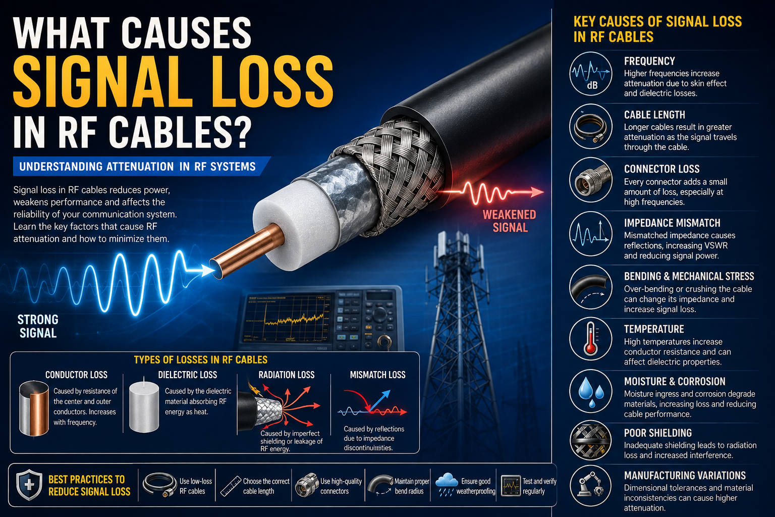
RF cable loss is caused by several physical and electrical mechanisms. The primary causes include conductor loss, dielectric loss, radiation loss, mismatch loss, connector loss, and mechanical or environmental damage.
The most important causes are explained below.
1. Conductor Loss
Conductor loss occurs because the metals used in RF cables have finite electrical resistance.
When an RF signal travels through the center conductor and outer conductor, some electrical energy is converted into heat.
The resistance of the conductor depends on:
Conductor material
Conductor diameter
Frequency
Temperature
Surface condition
Cable construction
Copper is widely used in RF cables because of its high electrical conductivity. Silver-plated conductors may be used in high-frequency applications where conductor surface performance is particularly important.
Larger conductors generally have lower resistance and can therefore provide lower attenuation.
2. Skin Effect
The skin effect is one of the most important causes of high-frequency conductor loss.
At low frequencies, electrical current is distributed relatively evenly throughout the conductor. As frequency increases, RF current tends to concentrate closer to the surface of the conductor.
This reduces the effective cross-sectional area available for current and increases AC resistance.
As a result, conductor loss generally increases with frequency.
The skin effect becomes especially important in:
Microwave systems
5G networks
Radar
Satellite communication
High-frequency test equipment
Aerospace electronics
Millimeter-wave applications
For high-frequency RF cables, conductor surface quality and plating can therefore have a significant effect on attenuation.
3. Dielectric Loss
The dielectric is the insulating material between the center conductor and outer conductor.
Although the dielectric is designed to minimize electrical losses, real dielectric materials absorb some RF energy.
This energy is converted into heat and contributes to cable attenuation.
Dielectric loss depends on:
Dielectric material
Frequency
Temperature
Dielectric constant
Loss tangent
Cable construction
Common RF dielectric materials include PTFE, FEP, polyethylene, and foamed polyethylene.
Low-loss RF cables often use specialized low-loss dielectric materials to reduce attenuation.
4. Frequency-Dependent Loss
RF cable attenuation generally increases as operating frequency increases.
A cable that performs well at 100 MHz may have substantially greater attenuation at several GHz.
This occurs because both conductor loss and dielectric loss become increasingly significant as frequency rises.
Therefore, RF cable specifications must always be evaluated at the actual operating frequency rather than using a single generic attenuation value.
For example, a cable intended for:
700 MHz
1800 MHz
3.5 GHz
6 GHz
18 GHz
40 GHz
will have different attenuation characteristics at each frequency.
5. Cable Length
Cable length has a direct impact on total signal loss.
Even a low-loss cable accumulates attenuation over distance.
The longer the RF transmission path, the greater the total insertion loss.
This is particularly important in:
Base-station feeder systems
Distributed antenna systems
Remote radio installations
Satellite ground systems
RF laboratory setups
Antenna feed systems
Long coaxial connections
Whenever possible, unnecessary cable length should be avoided.
However, cable length should never be reduced by violating installation requirements such as minimum bend radius or connector accessibility.
6. Cable Diameter
Cable diameter has a major influence on attenuation and power handling.
Larger RF cables generally have:
Lower conductor resistance
Lower attenuation
Higher power-handling capability
Better thermal performance
Smaller RF cables provide greater flexibility and easier installation but may have higher attenuation.
This creates a trade-off between cable size, flexibility, loss, weight, and installation requirements.
7. Dielectric Material Quality
The dielectric material plays a major role in RF cable performance.
A high-quality low-loss dielectric can significantly reduce signal attenuation.
Common materials include:
PTFE
FEP
PE
Foamed PE
Low-density fluoropolymers
Foamed dielectric structures are often used to reduce the effective dielectric constant and minimize dielectric losses.
For high-frequency and precision applications, the dielectric must also provide stable electrical characteristics across temperature and mechanical movement.
8. Impedance Mismatch
Impedance mismatch is another major source of RF signal degradation.
Most RF systems use controlled impedance, commonly 50 Ohm or 75 Ohm.
If the source, cable, connector, and load do not have compatible impedance, part of the RF energy is reflected back toward the source.
This reduces the power delivered to the load and can increase VSWR.
Impedance mismatch can occur because of:
Incorrect cable selection
Incorrect connectors
Poor connector termination
Damaged cable geometry
Incorrect adapters
Improper transitions
Manufacturing tolerances
9. Connector Loss
RF connectors are often overlooked when evaluating cable losses.
A cable may have excellent attenuation characteristics, but poorly designed or improperly installed connectors can introduce additional insertion loss and reflections.
Connector performance depends on:
Connector design
Frequency rating
Contact quality
Material
Plating
Termination method
Mechanical alignment
Connector torque
At higher frequencies, connector dimensions become extremely important.
Common high-frequency connectors include SMA, N-Type, 2.92mm, 2.4mm, 1.85mm, SMP, and SMPM.
10. Poor Connector Termination
Incorrect cable termination can create a discontinuity between the cable and connector.
Common termination problems include:
Incorrect stripping dimensions
Damaged dielectric
Improper crimping
Poor soldering
Loose contacts
Incorrect pin depth
Incorrect connector torque
Contamination
A poor termination can increase VSWR and insertion loss and can sometimes cause intermittent RF performance.
Precision cable assembly processes are therefore essential for high-frequency applications.
11. Bending and Mechanical Deformation
RF cables have specified minimum bend radii.
Bending a cable beyond its recommended radius can change the physical relationship between the center conductor, dielectric, and outer conductor.
This can result in:
Impedance changes
Signal reflections
Increased attenuation
Phase variation
Shield degradation
Mechanical damage
Semi-rigid and high-frequency cables can be particularly sensitive to deformation.
RF cable routing should therefore always follow the manufacturer’s recommended bend radius.
12. Compression of the Dielectric
Excessive mechanical pressure can deform the dielectric material.
Since the dielectric geometry directly influences impedance, compression can create local impedance discontinuities.
This may cause signal reflections and increase return loss.
Cable clamps, ties, mounting brackets, and routing hardware should therefore be installed carefully.
Over-tightening cable ties around RF cables should be avoided when it can deform the cable structure.
13. Shielding Imperfections
The outer conductor or shield is responsible for providing the RF return path and protecting the signal from electromagnetic interference.
If shielding is damaged, incomplete, poorly bonded, or improperly terminated, RF performance can degrade.
Potential problems include:
Signal leakage
External interference
Reduced isolation
Increased noise
Higher insertion loss in some system conditions
High-performance cables may use multiple layers of braid, foil, or solid outer conductors to improve shielding effectiveness.
14. Temperature
Temperature affects RF cable attenuation.
As temperature increases, conductor resistance generally increases. Dielectric properties can also change with temperature.
This can cause:
Higher attenuation
Phase changes
Impedance variation
Mechanical expansion
Reduced long-term reliability
High-temperature RF cables use specialized materials designed to maintain stable performance over wider temperature ranges.
Temperature-stable cables are particularly important in aerospace, defense, industrial, satellite, and outdoor telecom applications.
15. Moisture and Water Ingress
Moisture can significantly affect RF cable performance.
Water can penetrate damaged jackets, poorly sealed connectors, or improperly protected cable assemblies.
Moisture may alter the dielectric properties around the transmission line and can increase signal loss.
It can also cause:
Corrosion
Shield degradation
Connector failure
Insulation deterioration
Impedance instability
Outdoor RF cable installations should therefore use appropriate weatherproofing and sealing techniques.
16. Corrosion
Corrosion can affect both conductors and connectors.
Exposure to moisture, salt, chemicals, and environmental contaminants can degrade conductive surfaces.
Corrosion increases electrical resistance and can eventually cause intermittent or permanent connection failures.
Outdoor telecom and RF systems require suitable materials and environmental protection to minimize corrosion.
17. Radiation and Leakage Loss
Ideally, RF energy should remain confined within the transmission line.
However, imperfections in the shield, connector interfaces, or cable structure can allow electromagnetic energy to escape.
This is referred to as radiation or leakage.
Radiation losses are especially important in systems where electromagnetic compatibility and isolation are critical.
Applications such as defense electronics, radar, laboratories, and high-density wireless systems can require exceptionally high shielding effectiveness.
18. Connector and Adapter Mismatch
Using multiple adapters between an RF cable and equipment can introduce additional transitions.
Each transition can potentially introduce:
Insertion loss
Reflection
VSWR
Impedance discontinuity
Mechanical reliability issues
Where possible, a cable assembly should use the correct connector configuration instead of unnecessarily combining multiple adapters.
19. Cable Aging
RF cables can experience performance degradation over time.
Factors contributing to aging include:
UV exposure
Heat
Moisture
Repeated bending
Chemical exposure
Mechanical stress
Connector corrosion
Jacket deterioration
Cable aging can increase attenuation and reduce shielding effectiveness.
Regular inspection is particularly important for outdoor telecom installations and mission-critical RF systems.
20. Manufacturing Tolerances
RF cable performance depends heavily on dimensional accuracy.
Small variations in:
Center conductor diameter
Dielectric diameter
Shield dimensions
Concentricity
Connector geometry
can affect impedance and attenuation.
High-frequency cables therefore require precision manufacturing and quality control.
Difference Between Insertion Loss and Return Loss
Insertion loss and return loss are related to RF performance but represent different phenomena.
Insertion loss indicates how much signal power is lost while passing through the cable or component.
Return loss indicates how much signal is reflected back toward the source because of impedance mismatch.
A cable can have low insertion loss but still show poor return loss if there are impedance discontinuities.
Both parameters are important when evaluating RF cable assemblies.
How VSWR Relates to RF Cable Loss
VSWR indicates the degree of standing-wave behavior caused by impedance mismatch.
A higher VSWR generally indicates greater reflection.
Reflections can reduce the amount of power transferred to the load and may affect transmitter performance.
For high-frequency applications, low VSWR is particularly important because even small discontinuities can become significant as wavelength decreases.
How to Reduce Signal Loss in RF Cables
Reducing RF cable loss requires attention to cable selection, installation, connector quality, and environmental protection.
Choose a Low-Loss RF Cable
Select a cable specifically designed for the required frequency range and transmission distance.
Select the Correct Cable Diameter
If attenuation is critical, a larger-diameter low-loss cable may provide better performance.
Minimize Cable Length
Avoid unnecessary cable length while maintaining proper routing and installation requirements.
Use High-Quality Connectors
Select connectors rated for the operating frequency and application.
Maintain Proper Impedance
Use compatible 50 Ohm or 75 Ohm components throughout the RF signal path.
Avoid Excessive Bending
Always maintain the manufacturer’s specified minimum bend radius.
Protect Outdoor Connections
Use appropriate weatherproofing and sealing to prevent moisture penetration.
Inspect Cable Assemblies
Check for damaged jackets, crushed sections, loose connectors, corrosion, and excessive bending.
Use Proper Connector Torque
RF connectors should be tightened according to the manufacturer’s specified torque requirements.
Test the Cable
Use appropriate RF test equipment to verify insertion loss, return loss, VSWR, continuity, and other relevant parameters.
How to Measure RF Cable Signal Loss
RF cable signal loss can be measured using RF test equipment such as a vector network analyzer.
A typical measurement process involves connecting the cable between calibrated test ports and measuring its transmission characteristics.
Important measurements include:
Insertion loss
Return loss
VSWR
Phase response
Isolation where applicable
The measurement frequency range should cover the intended operating frequency of the cable.
Calibration is important because the measurement setup itself introduces losses and reflections.
RF Cable Loss in 5G Networks
5G systems can operate across a wide range of frequencies, including mid-band and higher-frequency spectrum.
At higher frequencies, cable attenuation becomes increasingly important.
RF cable selection for 5G applications should consider:
Operating frequency
Cable length
Insertion loss
VSWR
Power handling
Connector type
Shielding effectiveness
Temperature
Installation environment
Low-loss RF cable assemblies are commonly used between radios, filters, combiners, antennas, test equipment, and other RF components.
RF Cable Loss in Satellite Communication
Satellite communication systems often require high-performance RF cables because signal levels can be relatively low and transmission paths can be sensitive to attenuation.
Cable assemblies may be used between:
Antennas
Low-noise amplifiers
Filters
Transceivers
Frequency converters
Test equipment
Phase stability can also be important in precision satellite and ground-station applications.
RF Cable Loss in Radar Systems
Radar systems frequently operate at high frequencies and require reliable signal transmission.
Cable loss can affect the available transmit power and received signal level.
For radar applications, designers may prioritize:
Low attenuation
Low VSWR
High shielding
Phase stability
High power handling
Temperature stability
Precision connectors
RF Cable Loss in Test and Measurement
In RF laboratories, cable loss can directly influence measurement accuracy.
A test cable with unstable characteristics may introduce errors into measurements of devices under test.
Precision RF test cables are therefore designed for:
Low insertion loss
Stable phase
Low VSWR
High repeatability
High shielding effectiveness
Reliable connectors
Mechanical stability
Importance of Cable Routing
Cable routing is often overlooked during installation.
Improper routing can create mechanical stress and unnecessary attenuation.
Good RF cable routing practices include:
Maintain minimum bend radius
Avoid sharp bends
Avoid crushing the cable
Keep connectors properly supported
Avoid excessive cable loops
Prevent repeated flexing unless the cable is designed for it
Keep RF cables away from unnecessary sources of mechanical and electromagnetic interference
Choosing the Right RF Cable for Minimum Loss
The lowest-loss cable is not always the best cable for every application.
Cable selection should balance:
Frequency
Length
Attenuation
Diameter
Weight
Flexibility
Power
Temperature
Shielding
Connector configuration
Installation environment
For example, a large low-loss cable may provide excellent attenuation but may be unsuitable where space and flexibility are limited.
A smaller flexible cable may be easier to install but could introduce higher attenuation.
The correct cable is therefore the one that provides the required electrical and mechanical performance for the complete system.
RF Cable Loss: Key Factors at a Glance
The major causes of RF cable signal loss include:
Conductor resistance
Skin effect
Dielectric loss
Operating frequency
Cable length
Cable diameter
Impedance mismatch
Connector loss
Poor termination
Cable bending
Dielectric deformation
Shielding imperfections
Temperature
Moisture
Corrosion
Radiation leakage
Adapters and transitions
Cable aging
Manufacturing tolerances
Understanding these factors makes it easier to diagnose unexpected RF performance problems.
SRFS Teleinfra RF Cable and Cable Assembly Solutions
SRFS Teleinfra provides RF and telecom infrastructure products designed for communication, wireless, RF, 4G, 5G, testing, and network applications.
RF cable assemblies can be selected or configured according to requirements such as cable type, frequency range, impedance, connector combination, cable length, shielding, and environmental conditions.
For telecom infrastructure, RF testing, wireless networks, aerospace, defense, industrial communication, and other RF applications, selecting the correct low-loss RF cable and connector assembly can help maintain reliable signal transmission.
Conclusion
Signal loss in RF cables is caused by a combination of electrical, material, mechanical, environmental, and installation-related factors.
The most important contributors include conductor loss, skin effect, dielectric loss, frequency, cable length, impedance mismatch, connector quality, cable bending, temperature, moisture, corrosion, shielding imperfections, and manufacturing tolerances.
As RF systems move toward higher frequencies and more demanding applications, controlling cable loss becomes increasingly important.
Choosing the correct low-loss RF cable, maintaining proper impedance, using high-quality connectors, protecting cable assemblies from environmental conditions, following installation guidelines, and testing the finished assembly can significantly improve RF system performance.
For 4G, 5G, telecom, satellite communication, radar, aerospace, defense, broadcasting, and RF test applications, understanding the causes of signal loss is essential for achieving reliable and efficient signal transmission.
Frequently Asked Questions
What causes signal loss in RF cables?
The main causes include conductor resistance, skin effect, dielectric loss, cable length, high operating frequency, impedance mismatch, connector loss, poor termination, bending, temperature, moisture, corrosion, and shielding problems.
Does RF cable length affect signal loss?
Yes. Longer RF cables generally produce greater attenuation because the signal experiences loss continuously as it travels through the cable.
Why does RF cable loss increase with frequency?
Higher frequencies increase conductor and dielectric losses. The skin effect also becomes more significant, increasing the effective resistance of the conductor.
What is RF cable attenuation?
RF cable attenuation is the reduction in signal power as an RF signal travels through the cable. It is commonly specified in dB per unit length.
What is the difference between insertion loss and return loss?
Insertion loss represents the signal power lost while passing through the cable. Return loss represents the amount of signal reflected back toward the source because of impedance mismatch.
Does cable diameter affect RF signal loss?
Yes. Larger RF cables generally have lower conductor resistance and can provide lower attenuation, although they are usually less flexible and heavier.
Can bending an RF cable increase signal loss?
Yes. Excessive bending can deform the cable geometry, alter impedance, increase reflections, and potentially damage the shielding or dielectric.
Can connectors cause RF signal loss?
Yes. Connectors introduce a small amount of insertion loss, and poor-quality or improperly terminated connectors can create significant reflections and additional loss.
How can RF cable signal loss be reduced?
Use a suitable low-loss cable, minimize unnecessary cable length, select the correct diameter, maintain impedance matching, use high-quality connectors, avoid excessive bending, protect outdoor connections, and test the finished cable assembly.
What is the best RF cable for low signal loss?
There is no single best RF cable for every application. The appropriate cable depends on frequency, length, attenuation requirements, power, flexibility, temperature, shielding, connector type, and installation environment.
Does temperature affect RF cable loss?
Yes. Temperature can change conductor resistance and dielectric characteristics, which can increase attenuation and cause phase or impedance variations.
Can moisture increase RF cable loss?
Yes. Water ingress can alter dielectric properties, cause corrosion, degrade shielding, and increase signal attenuation.
Why is impedance matching important in RF cables?
Impedance matching minimizes signal reflections and helps transfer RF energy efficiently between the source, cable, and load.
How is RF cable loss measured?
RF cable loss can be measured using equipment such as a vector network analyzer. Common measurements include insertion loss, return loss, VSWR, and phase response.
Why are low-loss RF cables important in 5G?
5G systems can operate at relatively high frequencies where cable attenuation can become significant. Low-loss cables help preserve signal power between radios, antennas, filters, combiners, and other RF equipment.