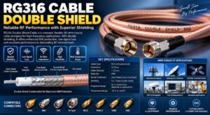
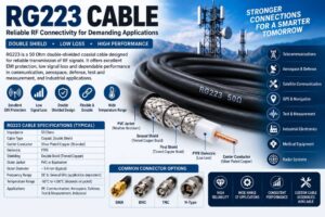
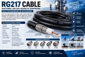
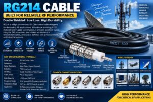
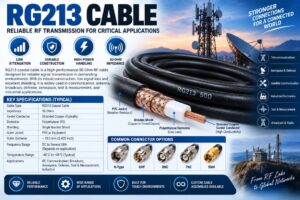
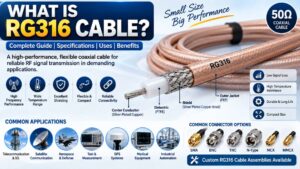
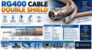
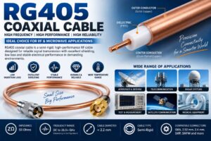
RF cable construction is a critical factor in determining the electrical performance, reliability, durability, and signal integrity of any radio frequency communication system. Radio frequency cables are specially engineered to transmit high-frequency signals between antennas, transmitters, receivers, amplifiers, filters, connectors, test equipment, and other RF components with minimum signal loss and interference.
Unlike ordinary electrical cables, RF cables are designed around controlled impedance, shielding effectiveness, dielectric properties, conductor geometry, and frequency-specific performance. Even small variations in the construction of an RF cable can affect insertion loss, return loss, VSWR, phase stability, power handling capability, and electromagnetic compatibility.
Understanding RF cable construction is therefore important for telecom engineers, RF designers, wireless network professionals, defense engineers, aerospace developers, laboratory technicians, system integrators, and procurement teams selecting cables for 4G, 5G, Wi-Fi, satellite communication, radar, broadcasting, and RF testing applications.
This guide explains the complete construction of an RF cable, including the center conductor, dielectric insulation, shielding, outer conductor, jacket, connectors, impedance control, cable types, manufacturing considerations, and applications.
What Is an RF Cable?
An RF cable is a coaxial or specialized transmission cable designed to carry radio frequency signals from one point to another while maintaining controlled electrical characteristics.
Most conventional RF cables use a coaxial construction. In a coaxial cable, the center conductor carries the RF signal, while an outer conductive shield surrounds the dielectric material and provides the return path. The outer conductor also protects the signal from external electromagnetic interference.
The basic structure of an RF coaxial cable consists of:
Center Conductor
Dielectric Insulator
Outer Conductor or Shield
Protective Jacket
RF Connectors
Each layer performs a specific function. Together, these components determine the cable’s electrical and mechanical performance.
Basic Structure of an RF Cable
The construction of a typical coaxial RF cable can be understood as a series of concentric layers.
The center conductor is located at the center of the cable. It is surrounded by a dielectric material that maintains the spacing between the center conductor and outer conductor. Around the dielectric is the outer conductor, which may consist of a solid tube, braided shield, foil shield, or combination of multiple shielding layers. Finally, an external jacket protects the cable against mechanical damage, moisture, chemicals, temperature, and environmental conditions.
A simplified RF cable structure is:
Center Conductor → Dielectric → Shield/Outer Conductor → Jacket
The geometry and material used for each layer must be carefully controlled because RF signals are extremely sensitive to changes in conductor dimensions and dielectric characteristics.
Center Conductor in RF Cable Construction
The center conductor is the primary signal-carrying element of an RF cable. It directly influences conductor resistance, attenuation, power handling, flexibility, and high-frequency performance.
Common materials used for RF cable center conductors include copper, silver-plated copper, copper-clad steel, and other specialized conductive materials.
Copper is widely used because it provides excellent electrical conductivity and relatively low resistance. Silver-plated copper may be used in high-performance RF applications because silver has excellent conductivity and can provide beneficial high-frequency surface performance.
RF cables may use different center conductor structures depending on their intended application.
Solid Center Conductor
A solid conductor consists of a single continuous metal conductor. Solid conductors generally provide excellent electrical performance and dimensional stability.
Advantages include:
Low conductor resistance
Excellent signal transmission
Stable impedance
Good mechanical consistency
High-frequency performance
Solid conductors are commonly found in semi-rigid, semi-flexible, and high-performance RF cables.
Stranded Center Conductor
A stranded conductor consists of multiple small wires twisted together. It provides significantly greater flexibility than a solid conductor.
Stranded RF cables are commonly used where repeated movement, routing around equipment, or installation flexibility is important.
The trade-off is that stranded construction can have somewhat different attenuation, impedance, and phase characteristics compared with a solid conductor.
Plated Center Conductors
High-performance RF cables may use plated conductors such as silver-plated copper.
Plating can improve surface conductivity and corrosion resistance. At high frequencies, RF current tends to concentrate toward the conductor surface due to the skin effect, making conductor surface quality particularly important.
Dielectric Material in RF Cables
The dielectric is the insulating material positioned between the center conductor and outer conductor.
The dielectric performs two major functions. First, it electrically isolates the center conductor from the outer conductor. Second, it establishes the physical spacing and electrical relationship required to maintain the cable’s characteristic impedance.
Common RF cable dielectric materials include:
PTFE
FEP
PE
Foamed polyethylene
Low-density PTFE
Special low-loss fluoropolymer materials
The dielectric constant of the material affects signal propagation velocity, impedance, attenuation, and phase characteristics.
PTFE Dielectric
PTFE is widely used in high-performance RF cables because of its excellent electrical properties, low dielectric loss, temperature resistance, and chemical stability.
PTFE is commonly found in semi-rigid and high-frequency RF cables used for aerospace, defense, laboratory, microwave, and instrumentation applications.
Foamed Dielectric
Foamed or cellular dielectric materials contain small air-filled spaces that reduce the effective dielectric constant.
Lower dielectric constant can help reduce dielectric losses and increase signal propagation velocity.
Foamed dielectric construction is commonly used in low-loss RF cables designed for telecommunications, wireless infrastructure, and long cable runs.
Outer Conductor and RF Shielding
The outer conductor is one of the most important parts of RF cable construction.
It performs two primary functions:
It provides the return path for the RF signal.
It shields the internal signal from external electromagnetic interference.
Depending on cable design, the outer conductor can consist of a solid metal tube, braided shield, foil shield, corrugated conductor, or combination of several shielding layers.
Solid Outer Conductor
A solid outer conductor provides excellent shielding effectiveness and mechanical protection.
Semi-rigid RF cables commonly use a solid metallic outer conductor, often manufactured from copper or another conductive alloy.
Because the conductor forms a continuous shield around the dielectric, it can provide excellent isolation from external electromagnetic fields.
The disadvantage is reduced flexibility compared with braided or flexible RF cables.
Braided Shield
Braided RF cable shields are constructed from multiple conductive wires woven around the dielectric.
Braided shielding provides a useful combination of flexibility and electromagnetic shielding.
RF cables may use single, double, or multiple braided shields depending on the required performance.
Braided cables are commonly used in:
RF test equipment
Communication systems
Wireless equipment
Instrumentation
Broadcasting
Laboratory systems
Foil Shield
A foil shield consists of a thin conductive foil wrapped around the dielectric.
Foil shielding can provide excellent coverage and help reduce electromagnetic leakage. It is often combined with a braided shield to provide both high shielding effectiveness and mechanical flexibility.
Dual and Multi-Layer Shielding
High-performance RF cables may combine foil, braid, and other conductive layers.
A multi-layer shield can improve shielding effectiveness and reduce signal leakage.
This is especially important in environments containing strong electromagnetic fields, high-power transmitters, sensitive receivers, radar equipment, and dense wireless infrastructure.
Cable Jacket
The outer jacket is the protective layer surrounding the RF cable.
Although the jacket does not normally carry the RF signal, it is essential for mechanical and environmental protection.
Common jacket materials include PVC, polyethylene, polyurethane, FEP, and other specialized materials.
The selection of jacket material depends on the installation environment.
For outdoor telecom applications, the jacket may need to resist:
UV radiation
Moisture
Rain
Temperature variation
Abrasion
Chemicals
Mechanical stress
For aerospace and defense applications, specialized low-smoke, flame-resistant, low-outgassing, or high-temperature materials may be required.
Characteristic Impedance in RF Cable Construction
Characteristic impedance is one of the most important electrical properties of an RF cable.
Common RF cable impedance values include:
50 Ohm
75 Ohm
50 Ohm cables are widely used in RF communication, wireless infrastructure, test equipment, microwave systems, aerospace, defense, and laboratory applications.
75 Ohm cables are commonly associated with video, television, broadcasting, and certain broadband applications.
Characteristic impedance depends primarily on the relationship between the center conductor diameter, dielectric diameter, dielectric constant, and outer conductor geometry.
For a coaxial cable, the impedance can be represented conceptually by the relationship between conductor dimensions and dielectric properties.
Maintaining consistent geometry throughout cable manufacturing is therefore essential for achieving stable impedance.
Why Impedance Matching Matters
When an RF cable is connected between two components with matching impedance, RF energy can transfer efficiently.
If the impedance is mismatched, part of the RF energy can be reflected toward the source.
This reflection can increase VSWR and return loss and reduce the effective power delivered to the load.
Poor impedance control can result in:
Signal reflections
Higher insertion loss
Increased VSWR
Reduced transmission efficiency
Measurement errors
Reduced system performance
For this reason, RF cable construction must maintain precise dimensional tolerances.
RF Cable Attenuation
Attenuation represents the reduction in signal power as an RF signal travels through a cable.
It is commonly expressed in dB per unit length.
RF cable attenuation depends on several factors, including:
Cable length
Conductor resistance
Dielectric losses
Operating frequency
Shield construction
Cable diameter
Material selection
Temperature
At higher frequencies, attenuation generally increases because conductor and dielectric losses become more significant.
For long-distance RF transmission systems, selecting a low-loss RF cable can significantly improve overall system performance.
Skin Effect and RF Cable Construction
The skin effect is an important phenomenon in high-frequency RF transmission.
As frequency increases, RF current tends to concentrate near the surface of a conductor rather than being distributed evenly throughout its entire cross-section.
This increases the effective AC resistance of the conductor.
Because of the skin effect, the surface quality and conductivity of RF conductors can become particularly important at microwave and millimeter-wave frequencies.
This is one reason high-frequency cables may use carefully controlled conductor surfaces or plated conductors.
RF Cable VSWR and Return Loss
VSWR, or Voltage Standing Wave Ratio, is an important measurement of how effectively RF energy is transferred through a transmission line.
A well-constructed RF cable with controlled impedance should exhibit low VSWR over its specified frequency range.
Return loss indicates the amount of signal reflected back toward the source due to impedance discontinuities.
Connector transitions, conductor geometry, dielectric variation, cable damage, and manufacturing defects can all contribute to RF reflections.
High-quality RF cable construction minimizes these discontinuities.
Phase Stability in RF Cables
Phase stability is particularly important in precision RF systems.
The phase of an RF signal can change when the cable is bent, stretched, compressed, or exposed to temperature changes.
Phase-stable RF cables are designed using specialized dielectric materials, conductor structures, and mechanical construction techniques to minimize these variations.
They are commonly used in:
Vector network analyzers
Radar systems
Phased-array antennas
Satellite communication
Aerospace testing
Defense electronics
RF measurement systems
5G test systems
Flexible RF Cable Construction
Flexible RF cables are designed to tolerate bending and routing.
They commonly use stranded center conductors and flexible braided shields.
Their construction provides a balance between electrical performance and mechanical flexibility.
Flexible RF cables are suitable for equipment interconnections, antenna connections, test systems, wireless infrastructure, and applications where cable movement is unavoidable.
Semi-Flexible RF Cable Construction
Semi-flexible cables provide greater mechanical flexibility than semi-rigid cables while maintaining controlled RF performance.
They are often used in applications where the cable must be routed around equipment but does not need frequent repeated movement.
Semi-flexible cables can provide a useful balance between:
Low attenuation
Controlled impedance
Shielding
Mechanical flexibility
Phase stability
Semi-Rigid RF Cable Construction
Semi-rigid RF cables use a solid outer metallic conductor, often formed around the dielectric.
The solid outer conductor provides excellent shielding and dimensional stability.
Semi-rigid cables are widely used in microwave and high-frequency applications where consistent electrical performance is more important than flexibility.
Typical applications include:
RF laboratory equipment
Aerospace electronics
Defense systems
Radar
Satellite communication
Test instrumentation
Microwave assemblies
Corrugated RF Cable Construction
Corrugated RF cables are commonly used in telecommunications and outdoor wireless infrastructure.
The outer conductor is formed with corrugations that allow the cable to flex while maintaining effective shielding.
These cables are widely used for antenna feeder systems and base-station installations.
Their construction offers a combination of:
Low attenuation
High power handling
Mechanical flexibility
Environmental durability
Strong shielding
RF Cable Connector Construction
The cable itself is only one part of a complete RF cable assembly.
Connectors provide the interface between the cable and RF equipment.
Common RF connectors include:
SMA
N-Type
TNC
BNC
SMB
MCX
MMCX
QMA
7/16 DIN
4.3/10
2.92mm
2.4mm
1.85mm
SMP
SMPM
U.FL/IPEX
The connector must maintain the same electrical characteristics as the cable.
A poorly installed connector can create impedance discontinuity, signal reflection, increased insertion loss, and reduced shielding effectiveness.
RF Cable Termination
RF cable termination involves attaching a connector to the cable while preserving the cable’s electrical geometry.
Depending on the cable type, termination may involve:
Crimping
Soldering
Clamping
Compression
Specialized assembly techniques
High-frequency cable assemblies require precision termination because even a small dimensional error can significantly affect performance at microwave and millimeter-wave frequencies.
Importance of Cable Geometry
One of the most important principles in RF cable construction is geometric consistency.
The relationship between the center conductor, dielectric, and outer conductor determines the electrical characteristics of the cable.
Manufacturing variations in:
Conductor diameter
Dielectric diameter
Shield thickness
Concentricity
Connector dimensions
Dielectric positioning
can affect impedance and RF performance.
Precision manufacturing is therefore essential for high-frequency cables.
RF Cable Shielding Effectiveness
Shielding effectiveness indicates how well a cable prevents electromagnetic energy from entering or escaping the cable.
High shielding effectiveness is especially important when multiple RF systems operate close to each other.
Applications requiring strong shielding include:
5G infrastructure
Radar systems
Defense electronics
RF laboratories
Satellite systems
Broadcasting
Wireless test systems
Dense communication environments
A combination of foil, braid, and solid conductive layers can be used to improve shielding performance.
RF Cable Power Handling
RF cable power handling refers to the maximum RF power that a cable can safely transmit under specified conditions.
Power handling depends on:
Cable diameter
Conductor material
Dielectric material
Operating frequency
Cable length
Temperature
VSWR
Cooling conditions
Dielectric breakdown characteristics
Larger RF cables generally provide greater power-handling capability, while smaller cables are commonly used for low-power signals and equipment interconnections.
Temperature Effects on RF Cable Construction
Temperature can influence cable attenuation, phase, mechanical properties, and dielectric characteristics.
High-temperature applications may require specialized dielectric and jacket materials.
Temperature-stable RF cables are used in environments such as:
Aerospace
Defense
Satellite systems
Industrial equipment
Test laboratories
Engine compartments
Outdoor telecom installations
Cable manufacturers may specify operating temperature ranges for the complete cable assembly.
RF Cable Construction for 5G Applications
5G networks require RF cables capable of supporting high-frequency signals, low insertion loss, controlled impedance, and reliable outdoor operation.
RF cables are used in:
5G base stations
Small cells
Distributed antenna systems
Massive MIMO systems
Remote radio units
Antennas
RF test equipment
Network infrastructure
As operating frequencies increase, cable losses and connector performance become increasingly important.
Low-loss and phase-stable RF cable assemblies can help maintain signal quality in demanding 5G applications.
RF Cable Construction for Telecom Infrastructure
Telecommunication systems use RF cables throughout the radio access network.
Typical applications include connections between:
Antennas and feeders
RRUs and antennas
Baseband and radio equipment
Filters and combiners
Duplexers and antennas
Test equipment and RF ports
Cable assemblies must be selected according to frequency, impedance, power, installation environment, connector type, and cable length.
RF Cable Construction for Aerospace and Defense
Aerospace and defense systems require highly reliable RF cables capable of operating under demanding environmental conditions.
RF cable assemblies may be exposed to:
Temperature extremes
Vibration
Mechanical shock
Humidity
Pressure changes
Electromagnetic interference
Repeated flexing
High-frequency operation
Specialized RF cables used in these systems may require low loss, phase stability, high shielding effectiveness, low outgassing, lightweight construction, and high-temperature resistance.
RF Cable Construction for Test and Measurement
Test and measurement equipment requires highly accurate RF cable assemblies because cable performance directly affects measurement results.
High-performance test cables may incorporate:
Precision connectors
Phase-stable dielectric materials
Low-loss construction
High shielding effectiveness
Low VSWR
Excellent repeatability
High mechanical reliability
Common applications include vector network analyzers, spectrum analyzers, signal generators, power meters, and RF calibration systems.
Common RF Cable Construction Types
RF cables can broadly be classified into several construction categories.
Flexible coaxial cables are designed for applications requiring frequent bending and easy installation.
Semi-flexible cables provide improved mechanical flexibility while maintaining good RF performance.
Semi-rigid cables provide excellent shielding, dimensional stability, and high-frequency performance.
Corrugated cables provide flexibility and low loss for outdoor telecom feeder applications.
Low-loss cables use specialized dielectric and conductor structures to minimize attenuation over longer cable lengths.
Phase-stable cables are designed to maintain predictable electrical phase under mechanical and temperature changes.
Factors to Consider When Selecting an RF Cable
Selecting the correct RF cable requires consideration of both electrical and mechanical requirements.
Frequency Range
Always select a cable rated for the complete operating frequency range of the application.
Characteristic Impedance
Confirm whether the system requires 50 Ohm or 75 Ohm impedance.
Cable Length
Longer cables generally introduce greater signal attenuation.
Insertion Loss
Choose a low-loss cable when maintaining signal power is important.
VSWR
A low VSWR specification is desirable for minimizing signal reflections.
Shielding
High shielding effectiveness is important in environments with strong electromagnetic interference.
Power Rating
Ensure that the cable can safely handle the required RF power.
Flexibility
Select flexible, semi-flexible, or semi-rigid construction according to installation requirements.
Temperature
Check the operating and storage temperature specifications.
Connector Type
The connector must be compatible with the equipment and cable’s electrical specifications.
Environmental Conditions
For outdoor applications, consider UV resistance, moisture protection, corrosion resistance, and mechanical durability.
Common RF Cable Construction Problems
Poor RF cable construction can lead to several performance issues.
Common problems include:
Incorrect impedance
Poor connector termination
Damaged dielectric
Inconsistent shielding
Conductor deformation
Excessive cable bending
Moisture penetration
Connector mismatch
Poor cable routing
Mechanical stress
Manufacturing dimensional variation
These problems can increase signal loss and reflections and reduce system reliability.
How to Improve RF Cable Performance
RF cable performance can be improved by using appropriate materials, maintaining accurate cable geometry, selecting suitable connectors, and following correct installation procedures.
Important practices include:
Use high-quality RF cables
Select cables according to frequency
Use correct impedance
Avoid excessive bending
Follow the minimum bend radius
Use compatible RF connectors
Apply proper connector torque
Protect outdoor cable assemblies from moisture
Avoid unnecessary cable length
Inspect connectors before installation
Use appropriate RF test equipment for verification
RF Cable Manufacturing Process
RF cable manufacturing generally involves multiple controlled processes.
The center conductor is produced or prepared according to the required diameter and material specification.
The dielectric is then applied around the conductor while maintaining dimensional consistency.
The outer conductor or shielding layer is applied around the dielectric.
Depending on the cable type, the shield may consist of braid, foil, solid metal, corrugated metal, or multiple layers.
The protective jacket is then applied.
The finished cable is inspected and tested for electrical and mechanical characteristics.
Cable assemblies may then undergo connector termination, electrical testing, visual inspection, and final quality control.
Testing of RF Cables
RF cables can undergo several electrical and mechanical tests.
Typical tests include:
Insertion loss
Return loss
VSWR
Impedance
Shielding effectiveness
Continuity
Insulation resistance
High-voltage testing where applicable
Phase stability
Temperature testing
Mechanical bending
Connector retention
Environmental testing
Testing requirements depend on the intended application and cable specification.
Why RF Cable Construction Matters
RF cable construction directly affects the overall performance of an RF system.
A cable may appear mechanically simple, but at high frequencies its internal dimensions, material properties, connector design, shielding, and manufacturing tolerances become critical.
A high-quality RF cable can help achieve:
Low signal loss
Stable impedance
Low VSWR
High shielding effectiveness
Reliable power transmission
Improved phase stability
Long service life
Consistent RF performance
For this reason, RF cable construction should always be evaluated as part of the complete RF transmission system rather than simply as a passive connection.
SRFS Teleinfra RF Cable Solutions
SRFS Teleinfra provides RF and telecom infrastructure solutions for communication, wireless, RF, 4G, 5G, testing, and network applications.
The product portfolio can include RF cables, cable assemblies, RF connectors, adapters, clamps, grounding accessories, weatherproofing solutions, and other telecom infrastructure components.
RF cable assemblies can be configured according to application requirements such as cable type, impedance, frequency range, connector combination, cable length, shielding, and environmental requirements.
For telecom, RF testing, wireless infrastructure, aerospace, defense, industrial, and communication applications, selecting the appropriate RF cable construction is essential for reliable signal transmission.
Future of RF Cable Construction
As wireless technologies move toward higher frequencies, RF cable construction will continue to evolve.
5G, advanced radar, satellite communication, aerospace electronics, high-frequency testing, and emerging 6G technologies are increasing demand for cables with lower loss, higher frequency capability, improved phase stability, better shielding, and more compact connector interfaces.
High-frequency applications are also increasing demand for precision cable assemblies using connectors such as 2.92mm, 2.4mm, 1.85mm, SMP, and SMPM.
Future RF cable designs are expected to focus on improved electrical performance, miniaturization, lightweight construction, thermal stability, mechanical reliability, and high-frequency signal integrity.
Conclusion
Understanding RF cable construction is essential for designing, selecting, installing, and maintaining reliable RF communication systems.
An RF cable is much more than a conductive wire. Its performance depends on the center conductor, dielectric material, outer conductor, shielding structure, protective jacket, connector termination, impedance control, and manufacturing precision.
For low-frequency and high-frequency applications alike, proper cable construction helps minimize signal loss, reflections, electromagnetic interference, and phase instability.
Whether used in 4G and 5G networks, RF laboratories, satellite communication, radar, aerospace, defense, broadcasting, data communication, or industrial systems, the right RF cable construction can significantly influence the performance and reliability of the complete RF system.
Frequently Asked Questions About RF Cable Construction
What is RF cable construction?
RF cable construction refers to the physical and electrical arrangement of the center conductor, dielectric, outer conductor or shield, protective jacket, and connectors used to transmit radio frequency signals.
What are the main parts of an RF cable?
The main parts are the center conductor, dielectric insulation, outer conductor or shielding, protective jacket, and RF connectors when the cable is supplied as a cable assembly.
Why is the dielectric important in an RF cable?
The dielectric electrically separates the center conductor from the outer conductor while controlling the spacing and electrical characteristics required for the cable’s characteristic impedance.
What materials are commonly used in RF cable construction?
Common materials include copper, silver-plated copper, PTFE, FEP, polyethylene, foamed polyethylene, PVC, polyurethane, and specialized fluoropolymer materials.
What is the most common RF cable impedance?
50 Ohm is widely used for RF communication, wireless infrastructure, microwave, aerospace, defense, and test equipment. 75 Ohm cables are also widely used in video and broadcasting applications.
What is the purpose of shielding in an RF cable?
Shielding provides the return path for the RF signal and helps prevent electromagnetic interference from entering or escaping the cable.
What is the difference between flexible and semi-rigid RF cables?
Flexible RF cables are designed for easier routing and repeated bending, while semi-rigid cables use a solid outer conductor and provide greater shielding, dimensional stability, and high-frequency performance.
Why does RF cable attenuation increase with frequency?
Higher frequencies increase conductor and dielectric losses, which generally results in greater signal attenuation as frequency increases.
What is VSWR in an RF cable?
VSWR, or Voltage Standing Wave Ratio, indicates the level of impedance mismatch and signal reflection within an RF transmission system. Lower VSWR generally indicates better impedance matching.
Why are RF connectors important in cable assemblies?
RF connectors provide the interface between the cable and equipment. Their dimensions, materials, termination quality, and impedance characteristics can significantly affect insertion loss, VSWR, return loss, and shielding.
What RF cables are used in 5G networks?
5G networks can use low-loss coaxial cables, flexible cable assemblies, corrugated feeder cables, phase-stable cables, and high-frequency precision cable assemblies depending on the application and operating frequency.
What is a low-loss RF cable?
A low-loss RF cable is designed to minimize signal attenuation through optimized conductor materials, dielectric construction, cable geometry, and shielding.
What is a phase-stable RF cable?
A phase-stable RF cable is designed to minimize changes in electrical phase caused by mechanical movement and temperature variation.
How does cable length affect RF performance?
As cable length increases, signal attenuation generally increases. Therefore, cable length should be kept as practical while meeting installation requirements.
How should an RF cable be selected?
RF cable selection should consider frequency range, impedance, insertion loss, VSWR, power handling, shielding effectiveness, cable length, flexibility, temperature range, environmental conditions, and connector type.