A Wilkinson Power Divider is a passive RF and microwave component used to divide an input signal into two or more output signals while maintaining excellent impedance matching and high isolation between output ports. It is widely used in wireless communication systems, RF testing equipment, radar systems, antenna networks, satellite communication, and microwave circuits.
Unlike conventional power dividers, a Wilkinson Power Divider offers an important advantage: it can distribute an RF signal with minimal reflection while reducing unwanted interaction between its output ports. This makes it particularly useful in applications where signal quality, low insertion loss, and stable RF performance are essential.
Wilkinson Power Dividers are commonly designed for equal power distribution, such as a 2-way divider that splits an input signal into two equal outputs. However, they can also be designed for unequal power division and multiple output configurations.
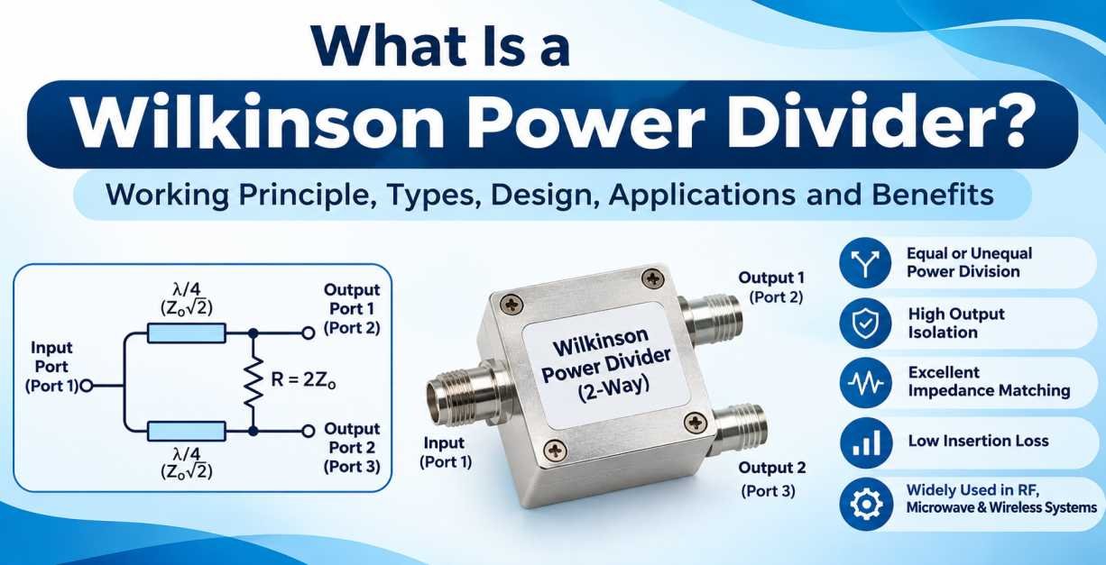
The component is generally constructed using transmission lines and an isolation resistor. Its design allows the outputs to remain isolated from each other while maintaining a matched impedance at the input and output ports.
What Is a Wilkinson Power Divider?
A Wilkinson Power Divider is a three-port or multi-port RF circuit that divides an incoming radio frequency signal into multiple output signals. It is designed to provide impedance matching at all ports and isolation between the output ports.
In a standard 2-way Wilkinson Power Divider, the incoming signal is divided into two equal parts. Ideally, each output receives half of the input power, corresponding to a 3 dB power division.
For example, when a 100 mW RF signal enters a 2-way Wilkinson Power Divider, each output receives approximately 50 mW under ideal conditions.
The main components of a conventional Wilkinson Power Divider include:
- Two quarter-wave transmission line sections.
- An isolation resistor connecting the output ports.
- An input port and two output ports.
- A carefully designed transmission line structure to maintain impedance matching.
The quarter-wave transmission lines help transform impedance, while the resistor provides isolation between the output ports.
How Does a Wilkinson Power Divider Work?
The working principle of a Wilkinson Power Divider is based on transmission line impedance transformation and the use of an isolation resistor.
When an RF signal enters the input port, the circuit divides the signal into two equal components. These signals travel through two quarter-wavelength transmission line branches and reach the output ports.
The transmission line sections are designed to provide impedance matching at the operating frequency. This helps minimize signal reflections and ensures efficient power distribution.
The isolation resistor plays an important role in maintaining isolation between the output ports. When the signals are balanced, ideally no current flows through the resistor. However, if an imbalance occurs between the output ports, the resistor absorbs the unwanted differential power, reducing interaction between the outputs.
The working process can be understood through the following steps:
- Input Signal Reception: An RF signal enters the Wilkinson Power Divider through the input port.
- Signal Splitting: The input signal divides into two equal signals in a standard 2-way configuration.
- Impedance Transformation: The quarter-wave transmission lines transform the impedance to maintain matching at the input.
- Output Signal Distribution: Both output ports receive approximately equal power.
- Output Isolation: The isolation resistor reduces unwanted coupling between the output ports when they are not perfectly balanced.
This combination of transmission lines and resistance makes the Wilkinson Power Divider an effective solution for RF signal distribution.
Wilkinson Power Divider Circuit Design
The conventional Wilkinson Power Divider uses a symmetrical circuit structure with two quarter-wave transmission line branches and one resistor connecting the output ports.
For a standard equal-split Wilkinson Power Divider with a 50-ohm system impedance, the design parameters are:
| Parameter | Typical Value |
|---|---|
| Input impedance | 50 Ohms |
| Output impedance | 50 Ohms |
| Number of output ports | 2 |
| Power division | Equal |
| Transmission line impedance | 70.7 Ohms |
| Isolation resistor | 100 Ohms |
| Electrical length | 90° |
| Operating frequency | Design dependent |
The quarter-wave transmission line impedance is calculated using:
\[ Z_t = \sqrt{2} \times Z_0 \]
Where:
- \(Z_t\) = Characteristic impedance of each branch.
- \(Z_0\) = System characteristic impedance.
For a 50-ohm system:
\[ Z_t = \sqrt{2} \times 50 = 70.7\ \Omega \]
The isolation resistor is calculated as:
\[ R = 2Z_0 \]
Therefore:
\[ R = 2 \times 50 = 100\ \Omega \]
These values apply to the conventional equal-split, two-way Wilkinson design. Practical implementations may use different structures and component values depending on frequency, bandwidth, substrate, and power requirements.
Main Characteristics of a Wilkinson Power Divider
Wilkinson Power Dividers offer several important electrical characteristics that make them suitable for demanding RF and microwave applications.
1. Equal Power Division
A standard 2-way Wilkinson Power Divider distributes the input power equally between two output ports.
Each output receives approximately half of the input power under ideal operating conditions.
2. High Output Isolation
One of the most important features is isolation between the output ports. The isolation resistor helps prevent unwanted signals from one output port from directly affecting the other output port.
This is particularly useful in antenna distribution networks and RF measurement systems.
3. Excellent Impedance Matching
Wilkinson Power Dividers are designed to provide impedance matching at the input and output ports at their intended operating frequency.
Proper impedance matching reduces reflections and improves power transfer efficiency.
4. Low Insertion Loss
An ideal equal-split 2-way Wilkinson Power Divider has a theoretical insertion loss of 3.01 dB from the input to each output because the input power is divided equally.
Practical insertion loss is slightly higher because of conductor losses, dielectric losses, resistor losses, and manufacturing tolerances.
5. Good Port-to-Port Isolation
The design provides high isolation between the two output ports, helping maintain signal stability when connected to different RF devices.
6. Compact RF Design
Wilkinson Power Dividers can be manufactured using microstrip, stripline, coaxial, and other transmission line technologies. This allows them to be integrated into compact RF and microwave systems.
Types of Wilkinson Power Dividers
Wilkinson Power Dividers are available in different configurations depending on the number of output ports, power distribution requirements, frequency range, and application.
1. 2-Way Wilkinson Power Divider
A 2-way Wilkinson Power Divider is the most common configuration. It divides one input signal into two equal output signals.
It is widely used in RF systems that require signal distribution to two antennas, receivers, or measurement channels.
Key features:
- Two output ports.
- Equal power distribution.
- High output isolation.
- Good impedance matching.
- Simple and compact circuit design.
2. 4-Way Wilkinson Power Divider
A 4-way Wilkinson Power Divider distributes one input signal into four output signals.
In an ideal equal-split configuration, each output receives one-quarter of the input power, corresponding to approximately 6.02 dB power division per output.
It is commonly used in antenna arrays, phased-array systems, and multi-channel RF networks.
3. 8-Way Wilkinson Power Divider
An 8-way Wilkinson Power Divider distributes the input signal across eight output ports.
Each output receives one-eighth of the input power in an ideal equal-split configuration, corresponding to approximately 9.03 dB power division.
These dividers are useful in large antenna systems, radar equipment, and RF distribution networks that require multiple signal paths.
4. Unequal Wilkinson Power Divider
An unequal Wilkinson Power Divider distributes the input signal between output ports according to a specific power ratio rather than dividing it equally.
For example, a divider may distribute 70% of the input power to one output and 30% to another.
These designs are useful when different RF devices require different signal power levels.
5. Multisection Wilkinson Power Divider
A multisection Wilkinson Power Divider uses multiple transmission line sections to achieve wider operating bandwidth compared with a conventional single-section design.
It is suitable for applications that require stable RF performance across a broader frequency range.
6. Wideband Wilkinson Power Divider
A wideband Wilkinson Power Divider is designed to operate over a broader frequency range while maintaining acceptable impedance matching and output isolation.
It is commonly used in broadband communication systems, RF testing, and microwave applications.
Wilkinson Power Divider vs Conventional Power Divider
Wilkinson Power Dividers and conventional power dividers both distribute RF signals, but their circuit structures and electrical performance can differ significantly.
| Parameter | Wilkinson Power Divider | Conventional Resistive Power Divider |
|---|---|---|
| Power division | Equal or unequal | Usually equal |
| Output isolation | High | Available through resistive paths |
| Impedance matching | Excellent at design frequency | Can be maintained over a broad range |
| Insertion loss | Low excess loss | Higher insertion loss |
| Circuit design | Transmission lines and isolation resistor | Resistor network |
| Efficiency | Generally higher | Generally lower |
| Applications | RF and microwave systems | General RF signal distribution |
A Wilkinson Power Divider is generally preferred when low excess insertion loss, impedance matching, and output isolation are important. Resistive dividers can be useful when broadband operation and simple construction are priorities.
Applications of Wilkinson Power Divider
Wilkinson Power Dividers are used across various RF, microwave, wireless communication, and electronic systems. Their ability to distribute signals while maintaining output isolation makes them valuable in many applications.
1. Wireless Communication Systems
Wilkinson Power Dividers are used in wireless communication infrastructure to distribute RF signals between different transmission and reception paths.
They support signal distribution in cellular communication systems, base stations, and other wireless networks.
2. Antenna Array Systems
Antenna arrays often require the same RF signal to be distributed across multiple antenna elements.
Wilkinson Power Dividers help distribute signals evenly to maintain consistent power levels across antenna elements.
They are particularly useful in phased-array antenna systems where accurate signal distribution is important.
3. Radar Systems
Radar systems use multiple RF channels and antenna elements to transmit and receive signals.
Wilkinson Power Dividers help distribute RF signals to different channels while reducing unwanted interaction between output paths.
4. Satellite Communication
Satellite communication equipment operates at microwave frequencies and requires reliable RF signal distribution.
Wilkinson Power Dividers are used in satellite RF networks, antenna feed systems, and microwave signal processing circuits.
5. RF Testing and Measurement Equipment
In RF laboratories and testing environments, a single RF signal may need to be distributed to multiple measurement instruments.
Wilkinson Power Dividers help provide controlled signal distribution for testing, calibration, and measurement applications.
6. Microwave Communication Systems
Microwave communication systems require stable signal distribution across different circuit stages.
Wilkinson Power Dividers are used in microwave transmitters, receivers, and signal processing networks.
7. Telecom Infrastructure
In telecom infrastructure, RF signals often need to be distributed across different antennas and communication equipment.
Wilkinson Power Dividers support efficient signal distribution in RF networks, indoor coverage systems, and base station installations.
8. Phased Array Systems
Phased-array systems use multiple antenna elements to control the direction of transmitted and received signals.
Wilkinson Power Dividers distribute RF signals to different elements and help maintain balanced signal paths.
Advantages of Wilkinson Power Divider
Wilkinson Power Dividers offer several advantages compared with other RF power distribution components.
High Output Isolation: The isolation resistor minimizes unwanted signal coupling between output ports.
Low Excess Insertion Loss: The transmission line structure provides efficient power distribution with relatively low additional loss.
Excellent Impedance Matching: The design supports good impedance matching at the operating frequency, reducing signal reflections.
Equal Power Distribution: Standard configurations provide balanced power distribution between output ports.
Compact Design: Wilkinson Power Dividers can be manufactured in compact PCB and microwave circuit formats.
Reliable RF Performance: They provide stable signal distribution when designed and operated within their specified frequency and power limits.
Multiple Configurations: They are available in 2-way, 4-way, 8-way, and unequal power division designs.
Limitations of Wilkinson Power Divider
Although Wilkinson Power Dividers offer excellent electrical performance, they also have certain limitations.
1. Limited Bandwidth in Conventional Designs
A traditional single-section Wilkinson Power Divider uses quarter-wave transmission lines and is optimized for a particular center frequency.
Its performance may deteriorate when operating significantly outside the designed frequency range.
2. Frequency-Dependent Performance
Impedance matching and isolation depend on the operating frequency. Therefore, the divider must be designed according to the intended frequency band.
3. Physical Size at Lower Frequencies
Quarter-wave transmission lines become physically longer at lower frequencies, which can increase the overall circuit size.
4. Power Handling Limitations
The power handling capability depends on the transmission line structure, substrate material, resistor rating, thermal management, and construction.
5. Design Complexity
Achieving high isolation, low insertion loss, and wide bandwidth requires careful RF circuit design and manufacturing precision.
How to Select the Right Wilkinson Power Divider
Selecting the right Wilkinson Power Divider is important for maintaining signal quality and achieving reliable performance in an RF system.
Before choosing a power divider, consider the following specifications.
1. Operating Frequency Range
The first factor to consider is the frequency range of your RF application.
Different Wilkinson Power Dividers are designed for different frequency bands, such as:
- 700 MHz to 2.7 GHz
- 1 GHz to 6 GHz
- 2 GHz to 8 GHz
- 6 GHz to 18 GHz
- 18 GHz to 40 GHz
These are illustrative frequency ranges, not standard specifications for every divider. Always check the manufacturer’s datasheet.
2. Number of Output Ports
Select the number of output ports according to your system requirements.
- 2-way: For two RF signal paths.
- 4-way: For four RF signal paths.
- 8-way: For eight RF signal paths.
The number of output ports determines how the input power is distributed.
3. Impedance
Most RF and microwave systems use a characteristic impedance of 50 Ohms.
Ensure that the Wilkinson Power Divider matches the impedance requirements of your connected RF components, cables, antennas, and equipment.
4. Insertion Loss
Insertion loss determines how much signal power is lost between the input and output ports.
For a 2-way equal-split divider, the ideal division loss is approximately 3.01 dB per output. Additional insertion loss should be considered when evaluating the actual device.
5. Isolation
Check the isolation specification between the output ports.
Higher isolation is important in applications where unwanted signal interaction can affect system performance.
6. Return Loss and VSWR
Return loss and Voltage Standing Wave Ratio (VSWR) indicate how effectively the divider is impedance matched.
Better matching helps minimize reflected power and improve signal transmission.
7. Power Handling Capacity
Check the maximum input power and continuous operating power supported by the divider.
The power rating should be suitable for the transmitter or RF system in which the component will be installed.
8. Connector Type
Depending on the application, Wilkinson Power Dividers may be available with different RF connector interfaces, including:
- SMA Connectors
- N-Type Connectors
- 2.92mm Connectors
- 3.5mm Connectors
- 7/16 DIN Connectors
Connector selection should match the RF cables and equipment used in the system.
9. Environmental Conditions
For outdoor telecom installations and industrial RF systems, consider operating temperature, humidity, vibration resistance, and enclosure protection.
These factors can affect long-term reliability and electrical performance.
Difference Between Wilkinson Power Divider and Power Splitter
The terms power divider and power splitter are frequently used interchangeably in RF engineering. However, their actual meaning can depend on the circuit design and application.
A Wilkinson Power Divider is a specific type of RF power divider that uses transmission lines and an isolation resistor to achieve impedance matching and output isolation.
A general power splitter is a broader category that includes resistive, reactive, hybrid, and transmission-line-based designs.
Therefore, every Wilkinson Power Divider is a type of power divider, but not every RF power divider uses the Wilkinson architecture.
Difference Between Wilkinson Power Divider and Directional Coupler
A Wilkinson Power Divider and a directional coupler are both passive RF components, but they perform different functions.
| Parameter | Wilkinson Power Divider | Directional Coupler |
|---|---|---|
| Main function | Divides input power | Couples a portion of RF power |
| Output ports | Two or more divided outputs | Through, coupled, isolated and input ports |
| Power distribution | Usually equal or specified ratio | Main power passes through with a smaller coupled portion |
| Output isolation | High isolation between divider outputs | Directional isolation |
| Common application | RF signal distribution | RF power monitoring and sampling |
Wilkinson Power Dividers are generally selected when a signal needs to be distributed across multiple paths, while directional couplers are preferred when a controlled portion of signal power needs to be sampled.
How Is Wilkinson Power Divider Performance Measured?
The electrical performance of a Wilkinson Power Divider is generally evaluated using a Vector Network Analyzer (VNA).
A VNA measures the scattering parameters (S-parameters) of the component to determine its RF characteristics.
Important measurements include:
S11 – Input Return Loss
S11 measures the amount of signal reflected back from the input port.
A lower reflection coefficient magnitude indicates better impedance matching.
S21 – Transmission from Input to Output 1
S21 measures how much input signal power reaches the first output port.
For an ideal equal-split 2-way Wilkinson Power Divider, the transmission magnitude is approximately -3.01 dB.
S31 – Transmission from Input to Output 2
S31 measures signal transmission from the input port to the second output port.
In an ideal symmetrical design, S21 and S31 should have nearly identical magnitudes.
S23 – Output Isolation
S23 measures the transmission between the two output ports.
Lower transmission between these ports indicates better isolation.
VSWR – Voltage Standing Wave Ratio
VSWR indicates the quality of impedance matching at the ports.
A lower VSWR generally indicates better matching and reduced reflected power.
Why Is an Isolation Resistor Used in a Wilkinson Power Divider?
The isolation resistor is one of the most important parts of a Wilkinson Power Divider.
In a standard 2-way equal-split design, a 100-ohm resistor is connected between the two output ports in a 50-ohm system.
When the input signal is divided equally and the output ports are properly matched, the signals arriving at both output ports have equal amplitude and phase. Ideally, the voltage across the resistor is zero, so no power is dissipated in it.
However, when the output signals become unbalanced because of mismatched loads or unequal signal conditions, a voltage difference develops across the resistor.
The resistor absorbs the unwanted differential energy and helps prevent one output port from affecting the other.
This is why the isolation resistor is essential for achieving high output-to-output isolation.
Why Choose SRFS Teleinfra for RF and Microwave Components?
SRFS Teleinfra provides RF and microwave components for wireless communication, telecom infrastructure, RF testing, and engineering applications.
For applications involving RF power distribution and signal management, selecting components with suitable electrical and mechanical specifications is essential.
When evaluating RF and microwave components, important considerations include:
- Operating frequency range.
- Impedance compatibility.
- Insertion loss.
- Return loss and VSWR.
- Isolation performance.
- Power handling capacity.
- Connector interface compatibility.
- Mechanical construction and environmental requirements.
SRFS Teleinfra focuses on RF and microwave connectivity solutions, including RF cables, cable assemblies, coaxial connectors, adapters, attenuators, terminations, and other telecom infrastructure components.
To explore RF and microwave connectivity solutions, visit the SRFS Teleinfra website.
Frequently Asked Questions (FAQs) About Wilkinson Power Divider
1. What is a Wilkinson Power Divider?
A Wilkinson Power Divider is a passive RF and microwave component that divides one input signal into two or more output signals while providing impedance matching and isolation between output ports.
2. What is the main purpose of a Wilkinson Power Divider?
Its main purpose is to distribute RF signals across multiple output paths while maintaining low excess insertion loss, good impedance matching, and high isolation between output ports.
3. How many output ports does a Wilkinson Power Divider have?
A standard Wilkinson Power Divider has three ports: one input port and two output ports. Multi-way versions with four, eight, or more output ports are also available.
4. What is the power division of a 2-way Wilkinson Power Divider?
A standard equal-split 2-way Wilkinson Power Divider distributes approximately 50% of the input power to each output port. The ideal division loss is approximately 3.01 dB per output.
5. What is the isolation resistor value in a Wilkinson Power Divider?
For a conventional 2-way equal-split Wilkinson Power Divider operating in a 50-ohm system, the isolation resistor is typically 100 Ohms.
6. Why is a Wilkinson Power Divider better than a resistive power divider?
A Wilkinson Power Divider generally offers lower excess insertion loss and better output isolation than a simple resistive divider. It is especially useful in RF and microwave applications requiring efficient signal distribution.
7. What is the function of quarter-wave transmission lines?
Quarter-wave transmission lines perform impedance transformation and help maintain proper impedance matching at the input and output ports at the design frequency.
8. Can a Wilkinson Power Divider split power unequally?
Yes. An unequal Wilkinson Power Divider can distribute input power according to a specified ratio, such as 70:30 or 60:40.
9. What is the ideal insertion loss of a 2-way Wilkinson Power Divider?
The ideal power division loss is approximately 3.01 dB per output. Practical insertion loss is slightly higher because of conductor, dielectric, and other circuit losses.
10. What is the difference between a 2-way and 4-way Wilkinson Power Divider?
A 2-way divider distributes input power across two output ports, with each receiving half the input power in an ideal equal-split design. A 4-way divider distributes power across four output ports, with each receiving one-quarter of the input power.
11. Where are Wilkinson Power Dividers used?
They are commonly used in wireless communication systems, antenna arrays, radar systems, satellite communication, microwave circuits, RF testing equipment, and telecom infrastructure.
12. Does a Wilkinson Power Divider work at all frequencies?
No. A conventional Wilkinson Power Divider is designed for a specific center frequency and operating bandwidth. Wideband and multisection versions can support broader frequency ranges.
13. What is the typical impedance of a Wilkinson Power Divider?
A 50-ohm characteristic impedance is commonly used in RF and microwave systems. Other impedance configurations can be designed according to application requirements.
14. How do you test a Wilkinson Power Divider?
A Vector Network Analyzer is commonly used to measure S-parameters, including input return loss, insertion loss, output isolation, and port matching.
15. Is a Wilkinson Power Divider a passive component?
Yes. It is a passive RF component that does not require an external power supply to divide an input signal.
Conclusion
A Wilkinson Power Divider is an important passive component in RF and microwave engineering. Its ability to divide input power while maintaining impedance matching and high isolation makes it a reliable choice for wireless communication, antenna arrays, radar systems, satellite communication, and RF testing applications.
The combination of quarter-wave transmission lines and an isolation resistor provides excellent performance in conventional equal-split designs. By selecting the correct frequency range, power handling capacity, impedance, insertion loss, isolation, and connector configuration, engineers can achieve reliable signal distribution in their RF systems.
For telecom infrastructure and microwave communication applications, understanding the working principle and specifications of a Wilkinson Power Divider helps in selecting the right RF signal distribution solution.