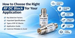
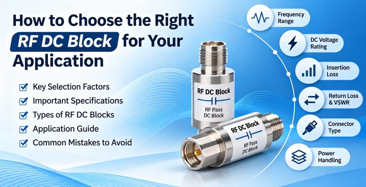
RF DC blocks are essential components in radio frequency (RF) and microwave communication systems. They allow RF signals to pass through while preventing unwanted direct current (DC) from flowing between connected devices. By separating DC and RF paths, these components help protect sensitive electronic equipment, maintain signal integrity, and improve the reliability of communication systems.
RF DC blocks are widely used in telecommunications, wireless communication, satellite systems, RF testing laboratories, radar equipment, antenna systems, and microwave applications. They are particularly important when connecting equipment that operates at different DC voltage levels or when a DC bias must be isolated from sensitive RF instruments.
However, choosing the right RF DC block requires more than simply selecting a connector type. Engineers must consider several electrical and mechanical parameters, including frequency range, insertion loss, return loss, voltage rating, capacitance, impedance, power handling capability, and connector compatibility.
Selecting an unsuitable DC block can result in signal degradation, impedance mismatch, equipment damage, or unreliable system performance.
This comprehensive guide explains how to choose the right RF DC block for your application, the important specifications to evaluate, different types of DC blocks, their applications, and common mistakes to avoid.
What Is an RF DC Block?
An RF DC block is a passive electronic component designed to allow alternating current (AC) radio frequency signals to pass while blocking direct current (DC).
It is commonly installed between RF components, instruments, antennas, amplifiers, and transmission lines to prevent DC voltage from reaching equipment that is not designed to handle it.
An RF DC block generally uses a series capacitor as its primary blocking element. The capacitor presents high impedance to DC while allowing RF signals to pass through within its specified operating frequency range.
In simple terms:
- RF Signal: Passes through the DC block.
- DC Voltage: Is blocked from passing through.
- Equipment Protection: Prevents unwanted DC voltage from reaching sensitive RF ports.
- Signal Transmission: Allows RF communication signals to travel between connected devices.
For example, when an RF signal generator is connected to a system that carries DC bias voltage, an RF DC block can help prevent that DC voltage from entering the signal generator.
How Does an RF DC Block Work?
The working principle of an RF DC block is based on the electrical properties of a capacitor.
A capacitor blocks steady-state DC because, after charging, it does not allow continuous DC current to flow through its dielectric material. However, it allows changing electrical signals, including RF signals, to pass.
The capacitive reactance determines how effectively the capacitor passes signals at different frequencies.
The formula for capacitive reactance is:
\[ X_C = \frac{1}{2\pi fC} \]
Where:
- \(X_C\) = Capacitive reactance in ohms
- \(f\) = Operating frequency in hertz
- \(C\) = Capacitance in farads
- \(\pi\) = Mathematical constant approximately equal to 3.1416
As frequency increases, capacitive reactance decreases. This allows higher-frequency RF signals to pass more easily.
At lower frequencies, capacitive reactance increases, which can cause higher insertion loss and reduced signal transmission efficiency.
This is why selecting the correct capacitance and operating frequency range is important when choosing an RF DC block.
Why Is Choosing the Right RF DC Block Important?
The performance of an RF DC block directly affects the electrical characteristics and reliability of an RF system.
Selecting the correct component provides several benefits.
1. Protection of Sensitive RF Equipment
Many RF instruments, including spectrum analyzers, signal generators, network analyzers, and receivers, have input ports that cannot tolerate external DC voltage.
An appropriately rated DC block prevents unwanted DC voltage from reaching these ports, helping reduce the risk of equipment damage.
2. Improved Signal Integrity
A high-quality RF DC block provides low insertion loss and good impedance matching. This helps maintain the quality of the transmitted RF signal.
3. Reduced Signal Reflection
Impedance mismatch can cause RF signals to reflect toward the source. Choosing a DC block with suitable return loss and VSWR specifications helps minimize these reflections.
4. Reliable RF System Performance
The correct DC block supports stable signal transmission across the required frequency range and operating conditions.
5. Flexible Equipment Integration
DC blocks allow engineers to connect RF equipment with different DC requirements without unnecessarily changing the overall system architecture.
Types of RF DC Blocks
RF DC blocks are available in different configurations depending on their construction, installation requirements, and electrical characteristics.
Understanding these types helps engineers select the appropriate component for their applications.
1. Inner DC Block
An inner DC block is designed to block DC voltage on the inner conductor while allowing the RF signal to pass.
It is commonly used in RF systems where DC voltage is present on the center conductor and needs to be isolated from connected equipment.
Key Features:
- Blocks DC on the center conductor.
- Allows RF signals to pass.
- Suitable for RF test and measurement applications.
- Available in different connector configurations.
2. Outer DC Block
An outer DC block is designed to interrupt DC continuity through the outer conductor while maintaining the required RF signal path.
It is useful in applications where DC isolation is required on the shield or outer conductor.
Key Features:
- Blocks DC through the outer conductor.
- Maintains RF transmission through the specified operating range.
- Supports specialized grounding and isolation requirements.
- Used in selected RF and microwave configurations.
3. Inner and Outer DC Block
An inner and outer DC block provides DC isolation on both the center conductor and outer conductor.
This configuration is suitable for applications requiring complete DC isolation between the input and output ports.
Key Features:
- Blocks DC on both conductors.
- Provides greater electrical isolation between connected devices.
- Suitable for sensitive RF measurement systems.
- Helps prevent unwanted DC current paths.
Important: The actual isolation behavior depends on the internal construction and grounding arrangement. Always verify the manufacturer’s DC isolation diagram and specifications before selecting a component.
10 Important Factors to Consider When Choosing an RF DC Block
Choosing the correct RF DC block requires evaluating electrical, mechanical, and environmental specifications.
The following factors can help engineers identify the right component for their application.
1. Operating Frequency Range
The operating frequency range is one of the most important specifications when selecting an RF DC block.
Every DC block is designed to operate within a defined frequency range. Below or above this range, the component may not provide acceptable insertion loss, return loss, or signal transmission performance.
For example:
- Low-frequency applications may require DC blocks designed for MHz-range signals.
- Wireless communication systems may require components operating across specific cellular frequency bands.
- Microwave applications may require DC blocks supporting several GHz.
- High-frequency test laboratories may need specialized microwave DC blocks operating at tens of GHz or higher.
Before selecting a DC block, identify the minimum and maximum frequencies used by your system.
Selection Tip: Choose a DC block whose specified frequency range covers the complete operating bandwidth of your application, including any necessary margin.
2. Impedance Matching
RF systems commonly use a characteristic impedance of 50 Ohms.
The DC block should match the impedance of the connected transmission line and equipment to minimize reflections.
A mismatch between the DC block and the RF system can lead to:
- Increased signal reflections.
- Higher VSWR.
- Reduced power transfer.
- Measurement inaccuracies.
- Degraded RF performance.
Most RF and microwave DC blocks are available in 50 Ohm configurations. However, always verify the impedance specification before purchasing.
3. Insertion Loss
Insertion loss refers to the reduction in signal power caused by inserting a component into an RF transmission path.
It is generally expressed in decibels (dB).
A lower insertion loss indicates that more of the original RF signal is transmitted through the DC block.
For example, if a DC block has an insertion loss of 0.5 dB, the output signal power will be lower than the input signal power by approximately 0.5 dB.
High insertion loss can negatively affect applications that require accurate measurements or low-noise signal transmission.
What to Look For:
- Low insertion loss across the required frequency range.
- Stable performance across the operating bandwidth.
- Suitable specifications for low-power and high-sensitivity systems.
4. Return Loss and VSWR
Return loss measures the amount of RF signal reflected because of impedance mismatch.
It is expressed in decibels. A higher return loss generally indicates better impedance matching.
VSWR (Voltage Standing Wave Ratio) is another parameter used to evaluate impedance matching.
A lower VSWR indicates better matching between the DC block and the connected RF system.
For example:
- VSWR of 1.10:1 indicates very good matching.
- VSWR of 1.20:1 indicates good matching.
- Higher VSWR values indicate greater mismatch.
The acceptable return loss and VSWR depend on the frequency range and performance requirements of the application.
When working with precision RF measurement systems, choose a DC block with suitable return loss performance across the entire operating bandwidth.
5. Maximum DC Voltage Rating
The maximum DC voltage rating specifies the highest DC voltage that the DC block is designed to withstand under its specified operating conditions.
This parameter is particularly important when working with:
- Antenna bias systems.
- RF amplifiers.
- Bias tees.
- Active antennas.
- Power-over-coax systems.
- RF testing equipment.
For example, if your application uses a 24V DC bias supply, you should select a DC block with a suitable voltage rating above the maximum expected operating voltage.
However, voltage rating alone is not enough. Engineers must also consider leakage current, dielectric strength, insulation characteristics, and manufacturer-defined operating conditions.
Selection Tip: Never operate a DC block beyond its specified DC voltage rating.
6. RF Power Handling Capability
Power handling capability indicates the maximum RF power that a DC block can safely handle under specified operating conditions.
The required power rating depends on the application.
For example:
- Low-power RF measurement systems may require relatively low power handling.
- Communication equipment may require moderate RF power handling.
- Transmitter and amplifier testing may require higher-rated DC blocks.
Exceeding the specified power rating can cause excessive heating, component degradation, or permanent damage.
When selecting a DC block, consider both average RF power and peak power, especially when handling pulsed or high-crest-factor signals.
7. Connector Type and Compatibility
Connector compatibility is another critical consideration.
RF DC blocks are available with different connector interfaces to match the requirements of RF and microwave systems.
Common connector options include:
- SMA
- N-Type
- BNC
- TNC
- 3.5mm
- 2.92mm
- 2.4mm
- 1.85mm
Each connector type has its own mechanical dimensions, frequency capabilities, and electrical characteristics.
For example, SMA connectors are commonly used in general RF and microwave applications, while 2.92mm, 2.4mm, and 1.85mm connectors are used in higher-frequency microwave and millimeter-wave systems.
When selecting a DC block, verify:
- Connector gender: Male or Female.
- Interface compatibility.
- Connector frequency rating.
- Mating dimensions.
- Thread type and mechanical configuration.
- Power and voltage specifications.
Never assume that two connectors are compatible simply because they can be physically connected.
8. Capacitance Value
Capacitance determines the ability of a DC block to pass RF signals, particularly at lower frequencies.
A higher capacitance generally results in lower capacitive reactance at a given frequency.
This can improve low-frequency signal transmission and reduce insertion loss near the lower end of the operating range.
However, increasing capacitance does not automatically guarantee better performance at all frequencies. Parasitic inductance, parasitic capacitance, component construction, and self-resonance also influence high-frequency behavior.
Choose a DC block based on its measured frequency response rather than capacitance alone.
9. Environmental and Mechanical Conditions
The operating environment can influence the reliability and lifespan of an RF DC block.
Consider the following environmental factors:
- Operating temperature.
- Storage temperature.
- Humidity.
- Mechanical vibration.
- Shock resistance.
- Corrosion resistance.
- Outdoor or indoor installation.
- Connector durability.
For outdoor telecommunications installations, environmental protection and mechanical robustness may be particularly important.
For laboratory applications, precision connector interfaces and repeatable electrical performance may be higher priorities.
10. Physical Size and Installation Requirements
The physical dimensions of an RF DC block should be suitable for the available installation space.
In compact RF systems, a bulky DC block may create installation difficulties or additional mechanical stress on connected components.
Consider:
- Overall length.
- Diameter.
- Weight.
- Connector orientation.
- Mounting requirements.
- Cable clearance.
- Accessibility for maintenance.
Compact DC blocks are useful in dense RF test setups, communication equipment, and modular microwave systems.
RF DC Block Specifications Comparison
Before purchasing an RF DC block, compare the important specifications provided in the manufacturer’s datasheet.
| Parameter | What to Check |
|---|---|
| Frequency Range | Minimum and maximum operating frequency |
| Impedance | Typically 50 Ohms |
| Insertion Loss | Lower loss for better signal transmission |
| Return Loss | Higher return loss for better matching |
| VSWR | Lower VSWR for reduced reflections |
| DC Voltage | Maximum allowable DC voltage |
| RF Power | Maximum average and peak power |
| Capacitance | Suitable capacitance for the operating bandwidth |
| Connector Type | SMA, N-Type, 2.92mm, 2.4mm, etc. |
| DC Isolation | Inner, outer, or inner and outer |
| Temperature | Operating and storage temperature |
| Construction | Mechanical design and material quality |
How to Select an RF DC Block Based on Your Application
Different RF applications have different electrical requirements. The right DC block should be selected according to the system’s operating frequency, voltage, power, and connector configuration.
1. RF Testing and Measurement Equipment
RF testing laboratories use DC blocks to protect sensitive instruments from unwanted DC voltage.
Common equipment includes:
- Spectrum analyzers.
- Vector network analyzers (VNAs).
- RF signal generators.
- RF power meters.
- Oscilloscopes with RF measurement accessories.
- Noise figure measurement systems.
For these applications, consider DC blocks with low insertion loss, excellent return loss, and suitable frequency coverage.
Precision connector interfaces are also important because repeated connections and disconnections can affect measurement accuracy.
2. Telecommunications Infrastructure
Telecommunications systems use DC blocks in RF signal paths where DC isolation is required between connected equipment.
Typical applications include:
- Base Transceiver Stations (BTS).
- Distributed Antenna Systems (DAS).
- In-Building Solutions (IBS).
- Cellular communication systems.
- RF distribution networks.
- Antenna feeder systems.
For telecommunications applications, select a DC block that supports the required operating frequency bands, connector configuration, and voltage rating.
3. Antenna Systems
Some antenna systems use DC power for active components, such as low-noise amplifiers (LNAs) and active antenna electronics.
A DC block can help isolate DC from equipment that requires an RF-only connection.
When choosing a DC block for an antenna system, consider:
- Antenna operating frequency.
- DC bias voltage.
- RF power level.
- Connector interface.
- Required isolation configuration.
- Insertion loss across the operating band.
Make sure the DC block is installed at the correct point in the signal path so that the required DC supply remains available to the active antenna components.
4. RF Amplifier Applications
RF amplifiers may operate with DC bias supplies that must be isolated from other connected RF devices.
A DC block can prevent unwanted DC voltage from entering equipment connected to the amplifier’s RF ports.
For these applications, check the maximum DC voltage, RF power handling capability, operating frequency, and impedance matching.
5. Microwave and Millimeter-Wave Applications
High-frequency microwave and millimeter-wave systems require carefully designed RF components.
At higher frequencies, even small changes in connector geometry and internal component construction can influence signal performance.
For these applications, prioritize:
- Wide operating frequency range.
- Low insertion loss.
- Excellent return loss.
- Precision connector interfaces.
- Low VSWR.
- Stable mechanical construction.
Depending on the operating frequency, connectors such as 2.92mm, 2.4mm, and 1.85mm may be appropriate.
Always verify the complete assembly’s specified frequency range rather than relying only on the connector’s nominal frequency capability.
6. Satellite Communication Systems
Satellite communication systems operate across specific RF and microwave frequency bands.
DC blocks can be used to isolate DC voltage from sensitive RF equipment while maintaining the required signal path.
Important selection parameters include frequency range, insertion loss, return loss, voltage rating, power handling, and connector compatibility.
RF DC Block vs Bias Tee: What Is the Difference?
RF DC blocks and bias tees are both used in RF systems to manage DC and RF signals. However, they perform different functions.
RF DC Block
An RF DC block allows RF signals to pass while preventing DC voltage from passing through its specified blocking path.
It is mainly used for DC isolation and equipment protection.
Bias Tee
A bias tee combines or separates DC and RF signals using a network of capacitors and inductors.
It is commonly used to supply DC power to an active RF device through the same coaxial cable that carries the RF signal.
| Feature | RF DC Block | Bias Tee |
|---|---|---|
| Primary Function | Blocks DC and passes RF | Combines or separates DC and RF |
| DC Transmission | Prevents DC through its blocking path | Provides a DC injection path |
| RF Transmission | Allows RF to pass | Allows RF to pass |
| Main Application | DC isolation | DC power injection |
| Typical Use | Equipment protection | Powering active RF devices |
| Construction | Commonly capacitor-based | Typically uses capacitors and inductors |
Which One Should You Choose?
Choose an RF DC block when you need to prevent DC voltage from reaching a connected device.
Choose a bias tee when you need to supply DC power and transmit RF signals through the same coaxial connection.
In some RF systems, both components may be required at different locations.
Common Mistakes to Avoid When Selecting an RF DC Block
Even a high-quality DC block may not perform correctly if it is selected or installed incorrectly.
Here are some common mistakes engineers should avoid.
1. Ignoring the Operating Frequency Range
Choosing a DC block without checking its frequency specifications can result in excessive insertion loss and poor signal transmission.
Always confirm that the complete application bandwidth falls within the component’s rated frequency range.
2. Selecting the Wrong Connector Interface
Connector gender, interface dimensions, and electrical compatibility must be verified before installation.
Using an incompatible connector can damage the mating interface or compromise RF performance.
3. Overlooking DC Voltage Rating
A DC block must withstand the maximum voltage expected in the system.
Selecting a component with an insufficient voltage rating can lead to insulation failure or permanent damage.
4. Ignoring RF Power Handling
RF power handling should be considered alongside DC voltage ratings.
A component that can withstand a particular DC voltage may not necessarily support the required RF power.
5. Focusing Only on Frequency
Frequency range is important, but it is not the only selection parameter.
Insertion loss, return loss, VSWR, voltage rating, and connector compatibility must also be evaluated.
6. Ignoring Temperature Conditions
Operating temperature affects the electrical performance and reliability of RF components.
Always check the manufacturer’s temperature specifications, especially for outdoor telecommunications and industrial applications.
7. Not Checking DC Isolation Configuration
An inner DC block and an inner-and-outer DC block do not provide identical isolation.
Verify which conductor requires DC isolation before selecting the component.
How to Install an RF DC Block Correctly
Proper installation is essential for achieving reliable RF performance.
Follow these general installation practices:
- Identify the DC source: Determine where DC voltage is present in the RF system.
- Identify the sensitive equipment: Check which device requires protection from DC voltage.
- Select the correct DC block: Verify frequency, voltage, power, and connector specifications.
- Check connector compatibility: Confirm the connector interface and gender.
- Inspect the connectors: Ensure that mating surfaces are clean and free from physical damage.
- Install in the correct signal path: Connect the DC block between the DC-carrying RF path and the equipment requiring isolation.
- Verify DC isolation: Confirm that the DC block provides the required isolation before connecting sensitive equipment.
- Check RF performance: Where necessary, measure insertion loss, return loss, and VSWR using appropriate test equipment.
Important Safety Note: Never assume that a DC block is safe to disconnect under voltage. Follow the manufacturer’s installation instructions, remove power before handling connections where required, and verify the DC voltage at the relevant interface.
How to Test the Performance of an RF DC Block
After installation, engineers may perform electrical tests to verify that the DC block meets the application’s requirements.
1. Insertion Loss Measurement
A Vector Network Analyzer (VNA) can be used to measure the insertion loss of an RF DC block.
The measurement helps determine how much RF signal power is lost when the component is inserted into the transmission path.
2. Return Loss Measurement
Return loss testing evaluates impedance matching and signal reflection.
A higher return loss generally indicates better impedance matching.
3. VSWR Measurement
VSWR measurements help identify impedance mismatch between the DC block and the connected RF system.
A lower VSWR generally represents better matching.
4. DC Isolation Test
A suitable electrical measurement setup can verify that DC does not pass through the specified blocking path.
The test voltage must remain within the manufacturer’s specified limits.
5. Frequency Response Test
A frequency sweep using a VNA can help verify the component’s performance across its operating bandwidth.
This test is particularly useful for broadband RF and microwave applications.
Applications of RF DC Blocks Across Different Industries
RF DC blocks are used in several industries where reliable RF signal transmission and DC isolation are important.
| Industry | Application |
|---|---|
| Telecommunications | BTS, DAS, IBS and RF distribution systems |
| Aerospace | RF communication and microwave equipment |
| Defence | Radar and secure communication systems |
| Satellite Communication | RF and microwave signal paths |
| Test and Measurement | Spectrum analyzers and VNAs |
| Wireless Networks | Antenna and RF infrastructure |
| Research Laboratories | Microwave testing and experimental RF setups |
| Electronics Manufacturing | RF circuit testing and validation |
What to Check Before Purchasing an RF DC Block
Before placing an order, prepare a technical requirement checklist to ensure that the selected component matches your system.
- Operating frequency range.
- Characteristic impedance.
- Maximum DC voltage.
- Maximum RF power.
- Insertion loss.
- Return loss.
- VSWR.
- DC isolation configuration.
- Connector type and gender.
- Operating temperature.
- Physical dimensions.
- Manufacturer datasheet and test specifications.
It is also important to consider the manufacturer’s quality control, product consistency, connector precision, and technical support.
Why Quality Matters When Selecting an RF DC Block
RF DC blocks are relatively small components, but they can significantly influence the performance of an RF system.
A poorly manufactured component may introduce excessive insertion loss, impedance mismatch, unreliable DC isolation, or inconsistent electrical performance.
When selecting an RF DC block, look for products with clearly documented electrical specifications and verified performance.
For critical communication and measurement systems, product quality and specification compliance should be considered just as important as price.
Frequently Asked Questions (FAQs) About RF DC Blocks
1. What is the main purpose of an RF DC block?
The main purpose of an RF DC block is to allow RF signals to pass while preventing DC voltage from passing through its specified blocking path. It is commonly used to protect sensitive RF equipment from unwanted DC voltage.
2. How does an RF DC block work?
An RF DC block generally uses a series capacitor. The capacitor blocks steady-state DC while allowing RF signals to pass within its specified frequency range.
3. What is the difference between an inner and outer DC block?
An inner DC block interrupts DC continuity through the center conductor, while an outer DC block interrupts DC continuity through the outer conductor. An inner-and-outer DC block provides isolation on both conductors.
4. Can an RF DC block be used at high frequencies?
Yes. RF DC blocks are available for microwave and millimeter-wave applications. The maximum operating frequency depends on the component’s internal design, connector interface, and electrical specifications.
5. What impedance is commonly used for RF DC blocks?
Most RF DC blocks used in telecommunications and microwave systems have a characteristic impedance of 50 Ohms. The impedance should match the connected RF equipment and transmission line.
6. Does an RF DC block affect signal quality?
Yes. An RF DC block introduces some insertion loss and may affect impedance matching. Selecting a component with low insertion loss and suitable return loss helps maintain signal quality.
7. What connectors are available for RF DC blocks?
RF DC blocks are available with various connector interfaces, including SMA, N-Type, BNC, TNC, 3.5mm, 2.92mm, 2.4mm, and 1.85mm, depending on the product design.
8. Can an RF DC block protect a spectrum analyzer?
Yes. An appropriately rated RF DC block can prevent unwanted DC voltage from reaching a spectrum analyzer’s RF input. However, its voltage and RF power ratings must be suitable for the application.
9. What is the difference between an RF DC block and an attenuator?
An RF DC block prevents DC voltage from passing while allowing RF signals to pass. An RF attenuator reduces the power level of an RF signal by a specified amount, measured in decibels.
10. How do I select the correct DC voltage rating?
Identify the maximum DC voltage present in your system and select a DC block with an appropriate voltage rating above the expected operating voltage. Also consider transient conditions and manufacturer specifications.
11. Can I use an RF DC block with a bias tee?
Yes. An RF DC block can be used alongside a bias tee when DC isolation is required at a particular point in the RF signal path. The components must be connected according to their DC and RF paths.
12. What happens if I use an RF DC block outside its frequency range?
Operating an RF DC block outside its specified frequency range can result in increased insertion loss, poor impedance matching, and degraded signal performance. Always verify the specified operating bandwidth.
13. Is an RF DC block suitable for outdoor applications?
Yes, certain RF DC blocks are designed for outdoor applications. Check their operating temperature, environmental protection, connector construction, and mechanical specifications before installation.
14. What is the most important specification when purchasing an RF DC block?
There is no single specification that determines suitability. Operating frequency, DC voltage rating, RF power handling, insertion loss, return loss, and connector compatibility should all be considered together.
Conclusion
Choosing the right RF DC block is essential for maintaining reliable signal transmission and protecting sensitive equipment in RF and microwave systems.
The selection process should begin with identifying the operating frequency range, impedance, DC voltage requirements, and RF power levels. Engineers should then evaluate insertion loss, return loss, VSWR, capacitance, connector compatibility, and environmental conditions.
Whether the application involves telecommunications infrastructure, antenna systems, RF testing equipment, microwave communication, or satellite systems, selecting a DC block that meets the complete electrical and mechanical requirements can improve system reliability and performance.
Always refer to the manufacturer’s datasheet and verify the component’s specifications before integrating it into an RF system.