1/2″ Feeder Cable is an essential component of modern wireless communication infrastructure, designed to transmit radio frequency (RF) signals between antennas, base stations, transmitters, receivers, and other communication equipment. It is widely used in cellular networks, telecommunications towers, distributed antenna systems (DAS), in-building wireless solutions, broadcasting infrastructure, and microwave communication installations.
As mobile communication technologies continue to evolve, the demand for reliable, low-loss RF transmission has increased significantly. Communication networks require cables that can carry high-frequency signals over considerable distances without excessive attenuation, signal leakage, or electromagnetic interference. A 1/2-inch feeder cable is designed to meet these requirements by offering a combination of low signal attenuation, excellent shielding, controlled impedance, mechanical strength, and reliable performance.
Unlike ordinary coaxial cables, 1/2-inch feeder cables are specifically engineered for professional RF infrastructure. They generally feature a corrugated outer conductor, a high-quality dielectric, and a protective outer jacket to maintain electrical performance and mechanical durability in demanding indoor and outdoor environments.
This comprehensive guide explains what a 1/2″ feeder cable is, how it works, its construction, types, technical specifications, applications, advantages, and important factors to consider when selecting the right cable for your communication system.
What Is a 1/2″ Feeder Cable?
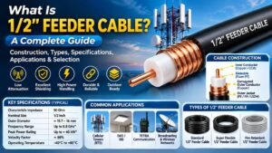
A 1/2″ Feeder Cable is a high-performance coaxial RF cable with an approximate outer diameter of half an inch (12.7 mm). It is designed to transmit radio frequency signals between communication equipment and antennas while minimizing signal loss and maintaining consistent electrical performance.
The term feeder cable refers to its role in feeding RF signals from a transmitter or base station to an antenna, or carrying received signals from an antenna back to communication equipment.
These cables are commonly designed with a 50 Ohm characteristic impedance, making them suitable for cellular communication, wireless networks, radio systems, and other professional RF applications.
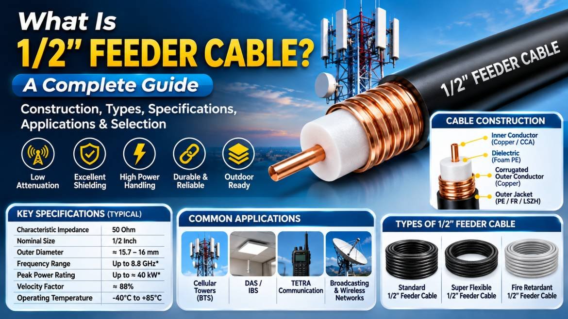
Most conventional 1/2-inch corrugated feeder cables use a coaxial construction consisting of an inner conductor, dielectric insulation, corrugated outer conductor, and protective outer jacket.
Their low attenuation characteristics make them particularly useful for installations where signal transmission over longer cable routes is required.
How Does a 1/2″ Feeder Cable Work?
A 1/2-inch feeder cable works by transmitting RF energy through its central conductor while the surrounding dielectric and outer conductor maintain the electromagnetic field within the cable.
The inner conductor carries the RF signal from the transmitter to the antenna. The dielectric material maintains the required separation between the inner and outer conductors, ensuring consistent electrical characteristics.
The outer conductor acts as an electrical return path and provides shielding against external electromagnetic interference. The outer jacket protects the cable from environmental conditions, moisture, abrasion, and mechanical damage.
Because the cable is designed with controlled characteristic impedance, it helps minimize signal reflections and supports efficient RF power transfer.
In a typical cellular base station installation, a 1/2-inch feeder cable connects radio equipment to an antenna system, allowing RF signals to travel between the two components with relatively low transmission loss.
Construction of a 1/2″ Feeder Cable
The construction of a 1/2-inch feeder cable plays an important role in determining its electrical performance, durability, and environmental resistance.
1. Inner Conductor
The inner conductor carries the RF signal through the cable. It is generally manufactured using copper or copper-based materials to provide excellent electrical conductivity.
Common characteristics include:
- High electrical conductivity
- Low conductor resistance
- Efficient RF signal transmission
- Good thermal performance
- Reliable long-term operation
2. Dielectric Insulation
The dielectric surrounds the inner conductor and maintains the required spacing between the inner and outer conductors.
Common dielectric materials include:
- Foam polyethylene
- Solid polyethylene
- Low-density polyethylene
The dielectric influences the cable’s characteristic impedance, capacitance, velocity factor, and attenuation.
3. Outer Conductor
The outer conductor provides shielding and acts as the return path for the RF signal.
In corrugated feeder cables, the outer conductor typically features a corrugated metallic structure that provides flexibility while maintaining effective electrical shielding.
Depending on the cable design, the outer conductor may be manufactured using copper or aluminium-based materials.
4. Protective Outer Jacket
The outer jacket protects the cable from external environmental conditions.
Common jacket materials include:
- Polyethylene (PE)
- Low Smoke Zero Halogen (LSZH)
- PVC
- Flame-retardant materials
For outdoor installations, UV-resistant and weather-resistant jackets help improve cable service life.
Types of 1/2″ Feeder Cables
Different types of 1/2-inch feeder cables are available depending on installation requirements, flexibility, fire safety, and electrical performance.
1. Standard 1/2″ Feeder Cable
Standard 1/2-inch feeder cable is commonly used in cellular communication infrastructure and outdoor antenna installations.
It generally features a corrugated copper outer conductor, foam polyethylene dielectric, and a protective polyethylene jacket.
Key features include:
- Low signal attenuation
- Excellent shielding performance
- 50 Ohm characteristic impedance
- High RF power handling capability
- Good mechanical strength
- Suitable for outdoor installations
2. 1/2″ Super Flexible Feeder Cable
Super flexible 1/2-inch feeder cable is designed for applications requiring easier routing and tighter bends.
Unlike standard feeder cables, super flexible versions are engineered with a more flexible corrugated structure, making them suitable for short connections and antenna jumper applications.
Common applications include:
- Antenna jumper connections
- Indoor wireless installations
- Distributed Antenna Systems (DAS)
- Base station connections
- Compact RF equipment installations
3. 1/2″ Fire Retardant Feeder Cable
Fire-retardant 1/2-inch feeder cable is designed for installations where fire safety and smoke emission requirements are important.
These cables may use flame-retardant, low-smoke, or halogen-free jacket materials depending on the applicable product standard.
Common applications include:
- Commercial buildings
- Airports
- Railway stations
- Shopping malls
- Hospitals
- Underground communication infrastructure
4. 1/2″ Low-Loss Feeder Cable
Low-loss feeder cables are engineered to minimize RF signal attenuation over long transmission distances.
They use optimized conductor dimensions and dielectric materials to maintain efficient signal transmission.
These cables are particularly suitable for:
- Cellular base stations
- Mobile communication towers
- DAS infrastructure
- Wireless broadband networks
- Professional RF transmission systems
Technical Specifications of 1/2″ Feeder Cable
The technical specifications of a 1/2-inch feeder cable depend on the manufacturer, construction, and product series. The following table presents representative specifications of a conventional 50 Ohm corrugated feeder cable.
1/2″ Feeder Cable Specification Table
| Specification | Typical Value |
|---|---|
| Cable Type | Corrugated Coaxial Feeder Cable |
| Nominal Cable Size | 1/2 Inch |
| Characteristic Impedance | 50 ± 1 Ohm |
| Inner Conductor | Copper-Clad Aluminium |
| Dielectric Material | Foam Polyethylene |
| Outer Conductor | Corrugated Copper Tube |
| Outer Jacket | Black Polyethylene |
| Overall Diameter | Approximately 15.7–16 mm |
| Velocity Factor | Approximately 88% |
| Capacitance | Approximately 76 pF/m |
| Maximum Frequency | Model dependent, commonly up to 8.8 GHz |
| Peak Power Rating | Up to approximately 40 kW |
| Operating Temperature | Typically -40°C to +85°C |
| Shielding Effectiveness | Model dependent, often above 110 dB |
Note: These are representative values, not universal specifications. Always refer to the manufacturer’s datasheet for the exact cable model. action-intl.com+3
Important Electrical Characteristics of 1/2″ Feeder Cable
Characteristic Impedance
Characteristic impedance is the electrical resistance presented by a cable to a travelling RF signal.
Most 1/2-inch feeder cables used in telecommunications have a nominal impedance of 50 Ohms.
Maintaining impedance matching between the cable, antenna, transmitter, and other RF components helps minimize signal reflections and improve transmission efficiency.
Attenuation
Attenuation refers to the reduction in signal power as an RF signal travels through a cable.
It is generally measured in decibels per 100 metres (dB/100m).
Lower attenuation means less signal power is lost during transmission. Cable attenuation generally increases with frequency and cable length.
This is one of the most important factors when selecting a feeder cable for cellular towers and long-distance RF installations.
VSWR (Voltage Standing Wave Ratio)
VSWR measures how effectively RF energy travels through a transmission line without being reflected toward the source.
A lower VSWR indicates better impedance matching.
A good-quality 1/2-inch feeder cable is designed to maintain low VSWR across its specified operating frequency range.
Return Loss
Return loss measures the amount of signal power reflected back toward the source because of impedance mismatch.
Higher return loss generally indicates better impedance matching and lower reflected power.
Shielding Effectiveness
Shielding effectiveness describes how effectively the outer conductor prevents electromagnetic interference from entering or escaping the cable.
A corrugated copper outer conductor provides excellent shielding and helps maintain signal integrity in electrically noisy environments.
Power Handling Capability
Power handling indicates how much RF power a cable can carry under specified operating conditions.
The actual continuous power capacity depends on frequency, ambient temperature, installation conditions, cable length, and connector performance. Peak power ratings should not be confused with continuous average power ratings.
Passive Intermodulation (PIM)
Passive Intermodulation occurs when unwanted frequencies are generated by nonlinear interactions between RF signals in passive components.
Low-PIM feeder cables are important in cellular infrastructure because unwanted intermodulation products can interfere with sensitive receiver signals.
Applications of 1/2″ Feeder Cable
1/2-inch feeder cables are widely used across telecommunications and wireless communication infrastructure.
1. Cellular Communication Towers
Cellular towers use 1/2-inch feeder cables to connect antennas with base station equipment.
They support RF signal transmission for mobile communication networks and help maintain reliable connectivity.
2. Distributed Antenna Systems (DAS)
DAS installations distribute wireless signals throughout large buildings and facilities.
1/2-inch feeder cables are used to connect antennas, splitters, couplers, and other RF distribution components.
Common DAS applications include:
- Airports
- Shopping malls
- Hospitals
- Hotels
- Office buildings
- Stadiums
- Railway stations
3. In-Building Solutions (IBS)
In-building wireless solutions improve cellular coverage in areas where outdoor signals are weak.
1/2-inch feeder cables help distribute RF signals between repeaters, antennas, amplifiers, and distribution networks.
4. 4G and 5G Networks
Modern cellular networks require reliable RF transmission between radio equipment and antenna systems.
1/2-inch feeder cables are used in suitable RF architectures where their frequency range, attenuation, and power-handling characteristics meet system requirements.
5. TETRA Communication Systems
TETRA (Terrestrial Trunked Radio) networks are used for mission-critical communication by emergency services, public safety organizations, transportation operators, and industrial facilities.
Feeder cables connect RF equipment with antennas to support dependable communication infrastructure.
6. Broadcasting Systems
Radio and television broadcasting installations use feeder cables to transfer RF signals between transmitters and antennas.
7. Wireless Repeater Systems
RF repeaters receive, amplify, and retransmit wireless signals to improve coverage.
1/2-inch feeder cables connect repeaters to indoor and outdoor antennas.
8. Satellite Communication
Certain satellite ground station installations use 50 Ohm feeder cables for RF connections between antennas and communication equipment, depending on the system frequency and power requirements.
Advantages of 1/2″ Feeder Cable
1/2-inch feeder cables offer several advantages for professional RF communication systems.
- Low Signal Attenuation: Designed to minimize RF power loss during transmission.
- Excellent Shielding: Corrugated metallic construction helps protect signals against electromagnetic interference.
- High Power Handling: Suitable models can support high RF power levels.
- Mechanical Strength: Corrugated construction provides structural strength and flexibility.
- Reliable Impedance: Controlled 50 Ohm impedance supports efficient RF transmission.
- Outdoor Durability: Protective jackets help resist moisture, UV exposure, and environmental conditions.
- Wide Frequency Compatibility: Suitable for multiple wireless communication frequency bands.
- Low PIM Options: Specialized versions support demanding cellular network installations.
- Long-Term Reliability: Proper installation and handling contribute to extended service life.
Limitations of 1/2″ Feeder Cable
Despite its advantages, 1/2-inch feeder cable has some limitations.
- Larger and heavier than smaller coaxial cables.
- Requires proper bending radius during installation.
- More expensive than many standard flexible coaxial cables.
- Requires compatible RF connectors and installation tools.
- Excessive bending may damage the corrugated outer conductor.
- Signal attenuation increases with cable length and operating frequency.
- Improper connector installation can affect VSWR and PIM performance.
1/2″ Feeder Cable vs 7/8″ Feeder Cable vs 1/4″ Feeder Cable
Choosing the appropriate feeder cable size depends on the required transmission distance, signal attenuation, installation space, flexibility, and power-handling requirements.
| Feature | 1/4″ Feeder | 1/2″ Feeder | 7/8″ Feeder |
|---|---|---|---|
| Cable Size | Smaller | Medium | Larger |
| Attenuation | Higher | Lower | Generally lower |
| Flexibility | High | Moderate | Lower |
| Weight | Light | Medium | Heavy |
| Installation Space | Low | Medium | High |
| Power Handling | Lower | Higher | Generally higher |
| Typical Application | Short RF connections | Antenna feeders and DAS | Longer RF feeder routes |
Comparison is general. Actual performance depends on cable construction, frequency, manufacturer, and product series.
How to Choose the Right 1/2″ Feeder Cable
Selecting the right 1/2-inch feeder cable is important for achieving reliable RF performance.
Consider the following factors before purchasing.
1. Operating Frequency
Check whether the cable supports the frequency bands used by your communication system.
2. Characteristic Impedance
Choose a 50 Ohm cable for most professional cellular and RF communication applications.
3. Attenuation
Compare attenuation values at your operating frequencies. Lower attenuation is generally preferable for longer cable routes.
4. Cable Construction
Evaluate the inner conductor, dielectric, outer conductor, and protective jacket materials.
5. Power Handling
Ensure that the cable supports the required continuous RF power under actual installation conditions.
6. Connector Compatibility
Choose compatible connectors such as 7/16 DIN, 4.3-10, N-Type, or other specified RF interfaces.
7. Environmental Conditions
For outdoor installations, check UV resistance, moisture protection, temperature rating, and jacket material.
8. PIM Performance
For cellular base stations and DAS applications, consider low-PIM cable and connector assemblies where required.
9. Bending Radius
Verify the manufacturer’s minimum single-bend and repeated-bend radius to avoid damaging the cable.
10. Manufacturer Quality
Select products supported by technical datasheets, electrical test reports, and relevant quality certifications.
Installation Guidelines for 1/2″ Feeder Cable
Correct installation is essential for maintaining electrical performance and mechanical reliability.
- Measure the required cable length before installation.
- Avoid sharp bends and twisting.
- Follow the specified minimum bending radius.
- Use compatible RF connectors.
- Ensure proper connector termination.
- Apply appropriate weatherproofing to outdoor connections.
- Provide suitable cable support and strain relief.
- Avoid excessive pulling force.
- Inspect the cable jacket for damage.
- Test VSWR and insertion loss after installation.
Maintenance of 1/2″ Feeder Cable
Regular inspection helps maintain reliable RF performance.
- Inspect connectors for corrosion and physical damage.
- Check the outer jacket for cracks or cuts.
- Verify weatherproofing at outdoor connection points.
- Inspect cable supports and mounting arrangements.
- Check for excessive bending or deformation.
- Perform periodic VSWR and RF transmission testing.
- Replace damaged connectors or cable sections when necessary.
Difference Between 1/2″ Standard and 1/2″ Super Flexible Feeder Cable
| Feature | Standard 1/2″ Feeder Cable | Super Flexible 1/2″ Feeder Cable |
|---|---|---|
| Construction | Corrugated outer conductor | More flexible corrugated construction |
| Flexibility | Moderate | High |
| Installation | Fixed cable routes | Tight spaces and jumper connections |
| Bending Radius | Generally larger | Generally smaller |
| Applications | BTS, DAS, antenna feeders | Antenna jumpers, compact installations |
| Mechanical Strength | Higher structural rigidity | Greater flexibility |
The main difference is mechanical flexibility. Standard feeder cables are generally preferred for fixed RF feeder routes, while super flexible versions are useful where easier routing and tighter bends are required. Powertec Information Portal+2
Future Trends in 1/2″ Feeder Cable Technology
The growth of 5G networks, private wireless communication, smart infrastructure, and advanced telecommunications is increasing the demand for high-performance RF feeder cables.
Manufacturers are focusing on developing advanced cable solutions with lower attenuation, improved shielding effectiveness, enhanced PIM performance, better flexibility, and improved fire safety.
Some important developments include:
- Advanced low-PIM cable construction
- Improved copper conductor technology
- Fire-retardant and halogen-free cable jackets
- Enhanced outdoor weather protection
- Improved RF performance at higher frequencies
- Lightweight and flexible cable designs
- Better compatibility with modern antenna systems
These developments will continue supporting reliable wireless communication infrastructure and high-performance RF transmission systems.
Conclusion
1/2″ Feeder Cable is an important component of modern RF and wireless communication infrastructure. Its low-loss characteristics, controlled 50 Ohm impedance, corrugated outer conductor, effective shielding, and high power-handling capability make it suitable for cellular towers, DAS, IBS, BTS installations, TETRA communication systems, wireless repeaters, and broadcasting networks.
Selecting the right 1/2-inch feeder cable requires careful consideration of frequency range, attenuation, impedance, power rating, PIM performance, connector compatibility, and environmental conditions. Proper installation and maintenance are equally important for ensuring long-term reliability.
As wireless communication technologies continue to advance, high-quality 1/2-inch feeder cables will remain an essential part of dependable RF signal transmission systems.
Frequently Asked Questions (FAQs)
1. What is a 1/2″ feeder cable?
A 1/2″ feeder cable is a 50 Ohm coaxial RF cable designed to transmit radio frequency signals between antennas, transmitters, receivers, and base station equipment with low signal attenuation.
2. What is the impedance of a 1/2″ feeder cable?
Most standard 1/2-inch feeder cables used in telecommunications have a characteristic impedance of 50 Ohms, making them suitable for professional RF communication applications.
3. What materials are used in 1/2″ feeder cable construction?
A typical 1/2-inch feeder cable consists of a copper-clad aluminium inner conductor, foam polyethylene dielectric, corrugated copper outer conductor, and protective polyethylene jacket.
4. What is the frequency range of a 1/2″ feeder cable?
The frequency range depends on the cable design and manufacturer. Many conventional 1/2-inch corrugated feeder cables support frequencies up to approximately 8.8 GHz, with some specifications extending higher.
5. What is the attenuation of a 1/2″ feeder cable?
Attenuation varies according to operating frequency and cable construction. It is generally measured in dB per 100 metres. Higher frequencies typically produce greater attenuation.
6. What is the maximum power handling capacity of a 1/2″ feeder cable?
Some standard 1/2-inch feeder cables have peak power ratings of approximately 40 kW. However, continuous average power capacity is considerably different and depends on frequency, temperature, and installation conditions.
7. Where is a 1/2″ feeder cable used?
It is widely used in cellular towers, BTS installations, DAS, IBS, 4G and 5G infrastructure, TETRA communication systems, RF repeaters, and broadcasting networks.
8. What is the difference between standard and super flexible 1/2″ feeder cable?
Standard feeder cables are designed for fixed RF transmission routes, while super flexible feeder cables are designed for easier installation in tight spaces and antenna jumper applications.
9. Which connectors are used with 1/2″ feeder cables?
Common connector options include 7/16 DIN, 4.3-10, N-Type, and other compatible RF connector interfaces, depending on the cable and equipment requirements.
10. Is a 1/2″ feeder cable suitable for outdoor applications?
Yes. Standard versions with UV-resistant and weather-resistant polyethylene jackets are suitable for outdoor communication installations when properly terminated and weatherproofed.
11. What is the difference between 1/2″ and 7/8″ feeder cable?
A 7/8-inch feeder cable has a larger diameter and generally offers lower attenuation and higher power-handling capability than a 1/2-inch cable. However, it is heavier and requires more installation space.
12. What is the minimum bending radius of a 1/2″ feeder cable?
The minimum bending radius depends on the cable construction. A typical standard 1/2-inch cable may have a single-bend radius of approximately 50–70 mm and a repeated-bend radius around 125 mm. Always follow the manufacturer’s datasheet.
13. Why is low PIM important in feeder cables?
Low Passive Intermodulation (PIM) performance helps minimize unwanted interference generated by nonlinear interactions in RF transmission systems. It is particularly important in cellular base stations and DAS installations.
14. How do you test a 1/2″ feeder cable?
A 1/2-inch feeder cable can be tested using a vector network analyzer (VNA), cable and antenna analyzer, or suitable RF test equipment to evaluate VSWR, return loss, insertion loss, and cable performance.
15. How long does a 1/2″ feeder cable last?
The service life depends on cable quality, installation, environmental exposure, connector condition, and maintenance. Properly installed outdoor feeder cables can provide reliable operation for many years.