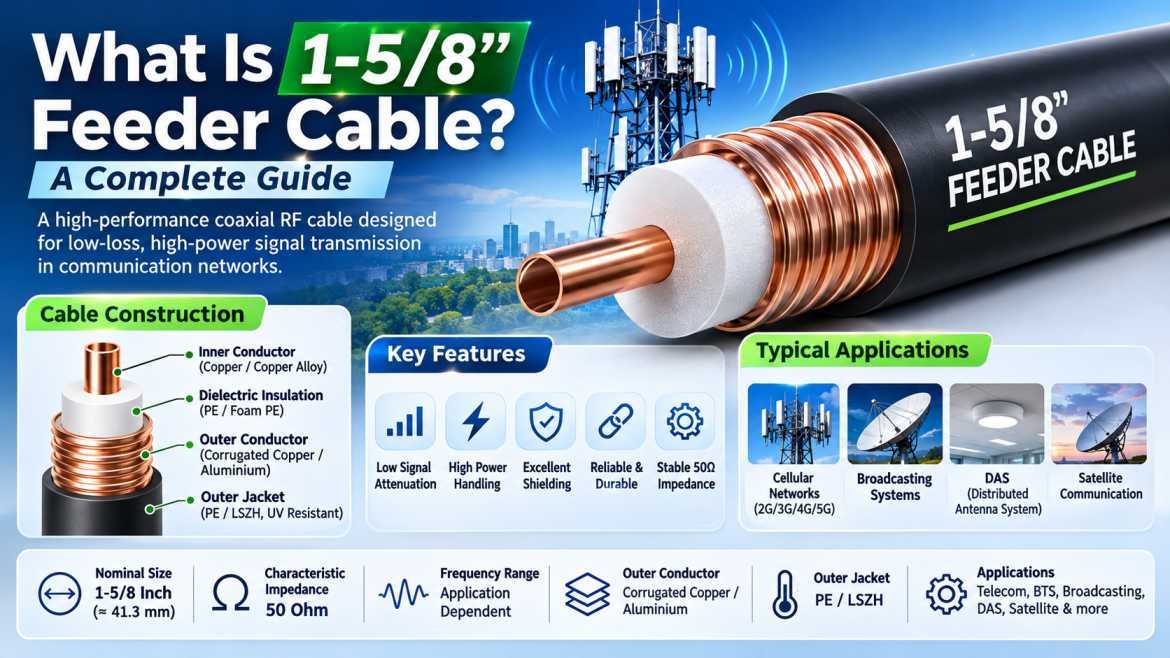
1-5/8″ Feeder Cable is a high-performance coaxial RF transmission cable designed to carry radio frequency signals between antennas, transmitters, receivers, and communication equipment with minimal signal loss. It is widely used in cellular base stations, telecommunications infrastructure, distributed antenna systems (DAS), broadcasting networks, satellite communication, and other high-power RF applications.
As wireless communication technologies continue to develop, maintaining reliable signal transmission has become increasingly important. Communication networks require cables that can handle high RF power, minimize attenuation, provide excellent shielding, and maintain stable electrical performance across different operating frequencies.
The 1-5/8″ feeder cable is engineered to meet these requirements. Its large-diameter construction provides excellent electrical performance, high power-handling capability, and lower attenuation compared with many smaller-diameter coaxial cables.
Unlike ordinary coaxial cables, 1-5/8″ feeder cables generally feature a corrugated outer conductor, a precision-engineered inner conductor, and a specialized dielectric material. This construction helps minimize signal leakage, improve flexibility during installation, and maintain consistent impedance.
In this comprehensive guide, we will explore what a 1-5/8″ feeder cable is, how it works, its construction, technical specifications, advantages, applications, and important factors to consider when selecting the right feeder cable for your communication infrastructure.
What Is a 1-5/8″ Feeder Cable?
A 1-5/8″ Feeder Cable is a large-diameter coaxial RF cable specifically designed for transmitting high-frequency radio signals with low attenuation and high power-handling capability.
The term 1-5/8″ refers to the nominal outer diameter of the cable, which is approximately 41.3 mm. It is commonly manufactured with a corrugated copper or aluminium outer conductor and a specially designed dielectric insulation system.
These cables are primarily used as transmission lines connecting radio equipment to antennas in high-power communication installations.
The primary functions of a 1-5/8″ feeder cable include:
- Transmitting RF signals between transmitters and antennas.
- Minimizing signal attenuation over long cable distances.
- Providing excellent electromagnetic shielding.
- Supporting high-power RF transmission.
- Maintaining consistent 50 Ohm characteristic impedance.
- Reducing signal leakage and electromagnetic interference.
- Supporting reliable communication network performance.
Due to their large conductor dimensions and carefully engineered construction, 1-5/8″ feeder cables are suitable for demanding RF and microwave communication applications.
How Does a 1-5/8″ Feeder Cable Work?
A 1-5/8″ feeder cable works on the principle of coaxial signal transmission. It carries radio frequency energy through a central conductor while an outer metallic conductor provides shielding and forms the return path for the electrical signal.
The dielectric material between the inner and outer conductors maintains electrical separation and determines important transmission characteristics such as impedance and velocity factor.
When an RF signal enters the cable, electromagnetic energy travels along the transmission line. The coaxial structure confines most of the electromagnetic field within the space between the inner and outer conductors.
This design provides several advantages:
- Reduced electromagnetic interference.
- Lower signal leakage.
- Stable impedance.
- Efficient RF power transmission.
- Improved signal quality over long distances.
The corrugated outer conductor also allows the cable to bend during installation while maintaining its mechanical and electrical properties within the manufacturer’s specified bend limits.
Construction of 1-5/8″ Feeder Cable
A 1-5/8″ feeder cable consists of multiple layers, each performing a specific electrical or mechanical function.
1. Inner Conductor
The inner conductor carries the RF signal through the cable.
It is generally manufactured using high-conductivity copper or copper-based materials to provide excellent electrical conductivity.
Key characteristics include:
- High electrical conductivity.
- Low conductor resistance.
- Efficient RF signal transmission.
- Excellent thermal performance.
- Long-term electrical stability.
The diameter and material of the inner conductor directly influence the cable’s impedance, attenuation, and power-handling performance.
2. Dielectric Insulation
The dielectric is positioned between the inner conductor and the outer conductor.
Its primary purpose is to maintain electrical separation while controlling the electromagnetic characteristics of the cable.
Common dielectric materials include:
- Polyethylene (PE).
- Foam polyethylene.
- Low-density polyethylene.
- Other RF-grade dielectric materials.
The dielectric affects characteristic impedance, velocity factor, capacitance, and attenuation.
3. Outer Conductor
The outer conductor provides electromagnetic shielding and serves as the return path for the RF signal.
In 1-5/8″ feeder cables, the outer conductor is commonly manufactured using corrugated copper or aluminium.
Its main functions include:
- Preventing external electromagnetic interference.
- Reducing RF signal leakage.
- Maintaining electrical continuity.
- Providing mechanical protection.
- Supporting efficient signal transmission.
The corrugated design improves flexibility compared with a completely smooth rigid outer tube.
4. Protective Outer Jacket
The outer jacket protects the internal cable structure against environmental and mechanical damage.
Common jacket materials include:
- Polyethylene (PE).
- Low Smoke Zero Halogen (LSZH).
- Flame-retardant polyethylene.
- UV-resistant polymer materials.
The appropriate jacket depends on whether the cable is installed indoors, outdoors, underground, or in specialized infrastructure environments.
Technical Specifications of 1-5/8″ Feeder Cable
The technical specifications of 1-5/8″ feeder cable may vary depending on the manufacturer, cable construction, and intended application.
The following table provides typical specification categories. Actual values should always be verified against the manufacturer’s datasheet.
| Parameter | Typical Specification |
|---|---|
| Cable Type | Corrugated Coaxial Feeder Cable |
| Nominal Outer Diameter | 1-5/8 Inch |
| Approximate Diameter | 41.3 mm |
| Characteristic Impedance | 50 Ohm |
| Inner Conductor | Copper / Copper-Based Material |
| Outer Conductor | Corrugated Copper / Aluminium |
| Dielectric | RF-Grade Polyethylene / Foam PE |
| Outer Jacket | PE / LSZH |
| Frequency Range | Application Dependent |
| Attenuation | Low-Loss Design |
| Shielding | High Shielding Effectiveness |
| Application | RF & Microwave Transmission |
Key Electrical Characteristics of 1-5/8″ Feeder Cable
1. Characteristic Impedance
Characteristic impedance is one of the most important parameters of an RF feeder cable.
Most telecommunications feeder cables are designed with a characteristic impedance of 50 Ohms.
Maintaining proper impedance matching between the transmitter, feeder cable, connectors, and antenna minimizes reflected power and improves overall transmission efficiency.
2. Attenuation
Attenuation refers to the reduction in signal power as an RF signal travels through a cable.
It is generally expressed in dB per 100 metres or dB per 100 feet at a specified frequency.
The large diameter of a 1-5/8″ feeder cable helps reduce conductor losses, making it suitable for long-distance RF transmission.
Actual attenuation depends on frequency, conductor material, dielectric construction, and cable design.
3. Return Loss
Return loss measures the amount of RF power reflected toward the signal source due to impedance discontinuities.
Higher return loss generally indicates better impedance matching.
Proper installation, compatible connectors, and correctly prepared cable ends help maintain good return loss performance.
4. VSWR
Voltage Standing Wave Ratio (VSWR) indicates the degree of impedance matching within an RF transmission system.
A lower VSWR indicates less reflected power and better matching.
In communication infrastructure, maintaining low VSWR helps improve transmitter efficiency and antenna system performance.
5. Power Handling Capacity
Power handling refers to the maximum RF power a cable can safely transmit under specified operating conditions.
The large conductor dimensions of 1-5/8″ feeder cable provide high power-handling capability compared with smaller feeder cables.
However, the actual rating depends on operating frequency, ambient temperature, cable installation, ventilation, and connector limitations.
Types of 1-5/8″ Feeder Cables
Different 1-5/8″ feeder cable constructions are available to meet specific installation and performance requirements.
1. Corrugated Copper Feeder Cable
Corrugated copper feeder cables use copper outer conductors with a corrugated structure.
They are designed for applications requiring excellent conductivity, low signal attenuation, and reliable shielding.
Common applications include:
- Cellular base stations.
- RF transmission systems.
- Antenna feeder installations.
- Broadcasting infrastructure.
- High-power communication networks.
2. Corrugated Aluminium Feeder Cable
Corrugated aluminium feeder cables use aluminium outer conductors to provide a comparatively lightweight cable construction.
They are suitable for installations where cable weight, handling, and mechanical requirements are important considerations.
3. Fire-Retardant Feeder Cable
Fire-retardant feeder cables are designed for installations where fire performance and smoke characteristics are important.
They may use specialized outer jacket materials to meet applicable building and infrastructure requirements.
These cables are commonly considered for:
- Indoor communication systems.
- Airports.
- Railway stations.
- Commercial buildings.
- Public infrastructure.
Comparison of Common RF Feeder Cable Sizes
Different feeder cable diameters are available for communication infrastructure.
The selection depends on transmission distance, attenuation requirements, RF power, installation space, and budget.
| Feeder Cable Size | Approximate Diameter | Typical Applications |
|---|---|---|
| 1/2 Inch | 12.7 mm | Short RF connections |
| 7/8 Inch | 22.2 mm | Cellular antenna systems |
| 1-1/4 Inch | 31.8 mm | Medium and high-power RF systems |
| 1-5/8 Inch | 41.3 mm | High-power, long-distance RF transmission |
Larger feeder cables generally provide lower attenuation at the same frequency when comparing similar cable technologies. However, they also require more installation space, larger connectors, and greater mechanical support.
Applications of 1-5/8″ Feeder Cable
1-5/8″ feeder cables are used in various industries where high-quality RF signal transmission is essential.
1. Cellular Communication Networks
One of the most important applications is cellular communication infrastructure.
Mobile network operators use feeder cables to connect base station equipment with antenna systems.
They support:
- 2G communication infrastructure.
- 3G cellular networks.
- 4G LTE networks.
- 5G communication installations.
- Multi-band antenna systems.
Their low-loss characteristics help minimize RF power loss between the radio equipment and antennas.
2. Base Transceiver Stations (BTS)
Base Transceiver Stations are essential components of cellular networks.
1-5/8″ feeder cables can be used to connect RF equipment to remote antenna installations, depending on the network architecture and system requirements.
They help maintain reliable signal transmission between communication equipment and antennas.
3. Distributed Antenna Systems (DAS)
Distributed Antenna Systems improve wireless coverage inside large buildings and other complex environments.
They are used in:
- Airports.
- Shopping malls.
- Stadiums.
- Hospitals.
- Railway stations.
- Commercial buildings.
Feeder cables form part of the RF distribution infrastructure, helping transport signals between system equipment and antenna distribution points.
4. Broadcasting Systems
Radio and television broadcasting stations require reliable RF transmission between transmitters and antennas.
1-5/8″ feeder cables can be used in broadcasting installations where their power-handling and attenuation characteristics meet the system requirements.
5. Satellite Communication
Satellite ground stations use specialized RF transmission cables to connect communication equipment with antenna systems.
Depending on the frequency range and installation requirements, large-diameter feeder cables can support RF signal distribution in satellite communication infrastructure.
6. Military and Defense Communication
Military communication infrastructure requires reliable signal transmission under demanding operating conditions.
Feeder cables may be used in:
- Radar installations.
- Ground communication systems.
- Tactical communication infrastructure.
- RF antenna networks.
- Specialized broadcasting systems.
7. Railway Communication Systems
Railway communication networks use RF infrastructure to support operational communication, wireless coverage, and signaling-related communication systems.
Feeder cables may be installed in railway infrastructure where suitable mechanical, electrical, and environmental specifications are required.
Advantages of 1-5/8″ Feeder Cable
1-5/8″ feeder cables offer several advantages for high-performance RF communication systems.
Low Signal Attenuation
Their large-diameter construction helps minimize signal losses, particularly in long-distance RF transmission applications.
High Power Handling
The large conductor dimensions support higher RF power transmission compared with many smaller coaxial cables.
Excellent Shielding
The corrugated metallic outer conductor provides effective protection against external electromagnetic interference.
Reliable Signal Transmission
A controlled coaxial structure helps maintain consistent impedance and reduces unwanted signal reflections.
Mechanical Durability
The corrugated construction provides a balance of flexibility and mechanical strength.
Suitable for Outdoor Installation
When supplied with an appropriate weather-resistant outer jacket, the cable can be used in outdoor telecommunications infrastructure.
Long-Term Performance
High-quality materials and proper installation contribute to reliable long-term operation.
1-5/8″ Feeder Cable vs Smaller Coaxial Cables
Understanding the difference between feeder cable sizes helps engineers select the appropriate cable for their RF infrastructure.
| Feature | 1-5/8″ Feeder Cable | Smaller RF Cable |
|---|---|---|
| Diameter | Approximately 41.3 mm | Smaller |
| Attenuation | Generally Lower | Generally Higher |
| Power Handling | Generally Higher | Application Dependent |
| Flexibility | Less Flexible | Often More Flexible |
| Installation Space | More Required | Less Required |
| Cable Weight | Higher | Lower |
| Applications | High-Power RF Systems | General RF Connections |
How to Choose the Right 1-5/8″ Feeder Cable
Selecting the right feeder cable is essential for achieving reliable RF transmission and minimizing system losses.
Consider the following factors before purchasing.
1. Operating Frequency
Check the frequency range of the communication system.
Cable attenuation increases with frequency, so the selected cable must support the complete operating frequency range.
2. Characteristic Impedance
Ensure that the feeder cable has the correct impedance.
Most cellular and telecommunications RF systems use 50 Ohm cables.
3. Attenuation Specifications
Compare attenuation values at the actual operating frequencies.
Lower attenuation helps minimize signal loss over long cable runs.
4. Power Handling
Determine the maximum RF power transmitted through the cable.
Consider operating temperature, installation conditions, and connector power limitations.
5. Outer Conductor Material
Choose between copper and aluminium construction according to electrical performance, weight, mechanical requirements, and environmental conditions.
6. Connector Compatibility
Verify that the connectors match the cable dimensions and interface requirements.
Common feeder cable connector interfaces include:
- 7/16 DIN.
- 4.3-10.
- N-Type.
- Other manufacturer-specific feeder interfaces.
7. Environmental Conditions
For outdoor installations, consider UV resistance, moisture protection, temperature variation, and corrosion resistance.
8. Manufacturer Quality
Always select feeder cables from reliable manufacturers that provide technical datasheets, test reports, and traceable product specifications.
Installation Guidelines for 1-5/8″ Feeder Cable
Correct installation is essential for maintaining the electrical and mechanical performance of feeder cables.
Follow these best practices:
- Maintain the manufacturer’s recommended minimum bending radius.
- Avoid sharp bends and excessive mechanical stress.
- Use compatible connectors designed for the exact cable type.
- Follow the correct cable preparation procedure.
- Ensure proper connector installation and tightening torque.
- Protect outdoor cable connections against moisture.
- Provide suitable mechanical support.
- Use appropriate grounding and bonding arrangements.
- Avoid crushing or deforming the corrugated outer conductor.
- Inspect the complete installation before commissioning.
Improper installation can increase VSWR, cause signal reflections, and reduce overall communication system performance.
Common Problems in 1-5/8″ Feeder Cable Installations
Even high-quality feeder cables can experience performance problems if they are not installed or maintained correctly.
High VSWR
Possible causes include incorrect connector installation, damaged cable sections, impedance mismatches, and moisture ingress.
Increased Signal Attenuation
Excessive bending, damaged conductors, poor connector interfaces, and unsuitable cable selection can increase transmission loss.
Water Ingress
Damaged jackets or improperly sealed connectors can allow moisture to enter the cable system.
Connector Damage
Incorrect installation tools, excessive tightening, and repeated mechanical stress can damage connector interfaces.
Mechanical Deformation
Crushing, excessive bending, and improper cable handling can affect the cable’s electrical performance.
Regular inspection and RF testing help identify these issues before they affect network performance.
Testing and Maintenance of 1-5/8″ Feeder Cable
Testing helps verify that the feeder cable meets the required electrical performance specifications.
Common testing methods include:
VSWR Testing: Measures the impedance matching performance of the cable and connected RF system.
Return Loss Testing: Evaluates the amount of reflected RF power.
Insertion Loss Testing: Measures signal attenuation through the transmission path.
Distance-to-Fault Testing: Helps identify cable faults, connector problems, and impedance discontinuities along the cable.
Visual Inspection: Checks the outer jacket, connectors, bends, grounding, and mechanical condition.
For critical communication installations, testing should be performed using properly calibrated RF test equipment and according to the cable manufacturer’s recommendations.
Future of Large-Diameter RF Feeder Cables
The development of wireless communication infrastructure continues to influence the demand for high-performance feeder cables.
Although many modern cellular networks use remote radio units and fiber-based fronthaul architectures, large-diameter RF feeder cables remain relevant in existing infrastructure, high-power broadcasting, specialized RF transmission systems, and antenna distribution networks.
Future developments are expected to focus on improved conductor materials, lower attenuation, enhanced environmental protection, better connector interfaces, and easier installation.
The continued expansion of 5G, private wireless networks, satellite communication, broadcasting, and critical communication infrastructure will maintain demand for reliable RF transmission solutions.
Conclusion
1-5/8″ Feeder Cable is an important component of high-power RF transmission infrastructure. Its large-diameter coaxial construction, controlled impedance, corrugated outer conductor, and low-loss characteristics make it suitable for cellular communication, broadcasting, DAS installations, satellite ground stations, and specialized RF systems.
Selecting the correct feeder cable requires careful evaluation of operating frequency, attenuation, power handling, impedance, conductor material, connector compatibility, and environmental conditions. Proper installation, testing, and maintenance are equally important for ensuring reliable signal transmission and long-term system performance.
As wireless communication infrastructure continues to expand, 1-5/8″ feeder cables remain a valuable solution for applications requiring dependable, efficient, and high-performance RF signal distribution.
Frequently Asked Questions (FAQs)
1. What is a 1-5/8″ feeder cable?
A 1-5/8″ feeder cable is a large-diameter coaxial RF cable designed to transmit high-frequency signals between antennas and communication equipment with low attenuation and high power-handling capability.
2. What is the diameter of a 1-5/8″ feeder cable?
The nominal diameter is 1-5/8 inches, approximately 41.3 mm. The actual dimensions may vary slightly depending on the manufacturer’s construction and product specifications.
3. What is the impedance of a 1-5/8″ feeder cable?
Most telecommunications 1-5/8″ feeder cables are designed with a characteristic impedance of 50 Ohms to match standard RF communication equipment.
4. Where is 1-5/8″ feeder cable used?
It is commonly used in cellular base stations, BTS installations, broadcasting systems, DAS networks, satellite ground stations, radar infrastructure, and specialized RF communication systems.
5. What materials are used in 1-5/8″ feeder cables?
These cables generally use copper or copper-based inner conductors, polyethylene or foam dielectric insulation, corrugated copper or aluminium outer conductors, and protective polymer jackets.
6. What are the advantages of 1-5/8″ feeder cable?
The main advantages include low attenuation, high power-handling capability, excellent shielding, stable impedance, mechanical durability, and reliable RF signal transmission.
7. What connectors are used with 1-5/8″ feeder cables?
Common connector interfaces include 7/16 DIN, 4.3-10, and other compatible feeder cable connectors. The correct connector must match the exact cable construction and dimensions.
8. What is the difference between 7/8″ and 1-5/8″ feeder cable?
A 1-5/8″ feeder cable has a larger diameter than a 7/8″ feeder cable. It generally provides lower attenuation and higher power-handling capability, but requires more installation space and heavier mechanical support.
9. Can 1-5/8″ feeder cable be used outdoors?
Yes. Feeder cables with suitable UV-resistant and weather-resistant outer jackets can be installed outdoors for telecommunications and antenna infrastructure.
10. How do you test a 1-5/8″ feeder cable?
It can be tested using RF test equipment to measure VSWR, return loss, insertion loss, and distance to fault. Visual inspection is also recommended to identify physical damage and connector issues.
11. What is the difference between corrugated copper and aluminium feeder cable?
Corrugated copper feeder cables offer excellent electrical conductivity, while aluminium versions can provide a lighter construction. The appropriate choice depends on attenuation, weight, environmental conditions, and installation requirements.
12. Why is 1-5/8″ feeder cable preferred for high-power RF applications?
Its large conductor dimensions help reduce electrical losses and support higher RF power transmission, making it suitable for demanding communication and broadcasting installations.
13. Does 1-5/8″ feeder cable support 5G communication?
Yes. It can be used in suitable 5G RF infrastructure, particularly in antenna feeder and distribution applications where its frequency, attenuation, and power ratings meet the system requirements.
14. What factors affect the performance of 1-5/8″ feeder cable?
Operating frequency, conductor material, dielectric properties, cable length, connector quality, impedance matching, temperature, and installation quality all influence cable performance.