
End Launch Connector
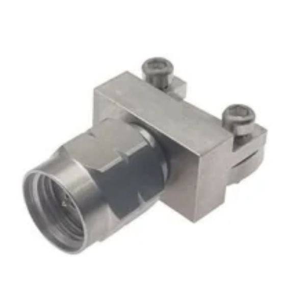
End Launch Connectors are precision-engineered RF connectors designed to provide a reliable transition between coaxial cables and printed circuit boards (PCBs). They are widely used in high-frequency RF and microwave circuits where signal integrity, impedance matching, compact design, and repeatable electrical performance are essential. At SRFS Teleinfra, we offer high-quality End Launch Connectors for RF testing, microwave communication, antenna systems, wireless infrastructure, aerospace, defense, and advanced electronic applications.
Our End Launch Connectors are designed for direct mounting onto PCB edges, enabling efficient connections between coaxial transmission lines and microstrip or coplanar waveguide circuits. Their precision-engineered interfaces help minimize signal reflections and insertion loss while maintaining stable 50 Ohm impedance. These connectors are suitable for RF modules, microwave circuits, laboratory instruments, spectrum analyzers, vector network analyzers (VNAs), antenna testing systems, and high-frequency electronic assemblies.
SRFS Teleinfra offers End Launch Connectors in different connector interfaces, mounting configurations, and frequency ranges to meet diverse engineering requirements. Our product range includes SMA End Launch Connectors and other configurations depending on availability and application needs. We focus on precision manufacturing, reliable electrical performance, and durable construction for demanding RF and microwave applications.
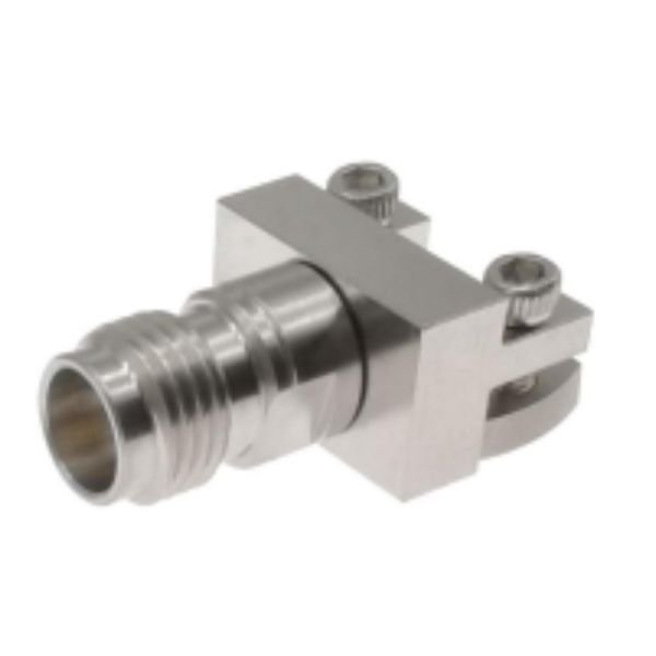
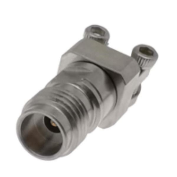
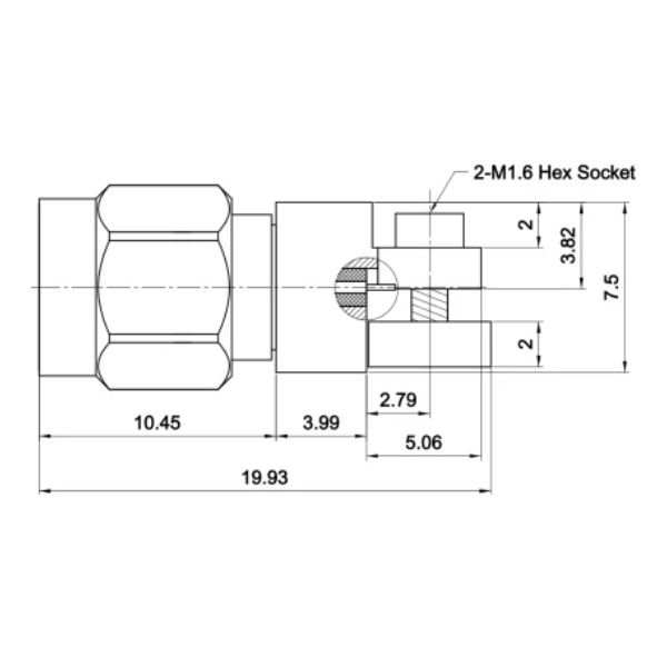
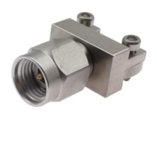
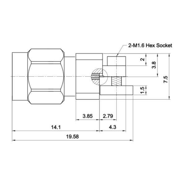
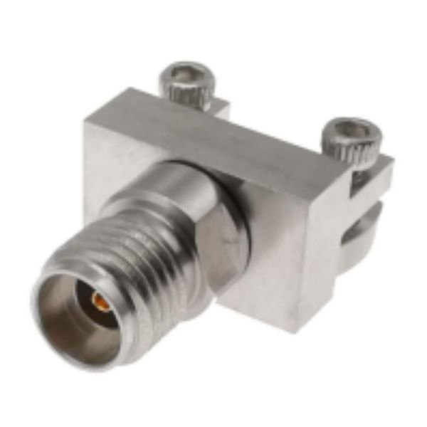
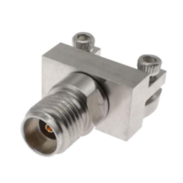
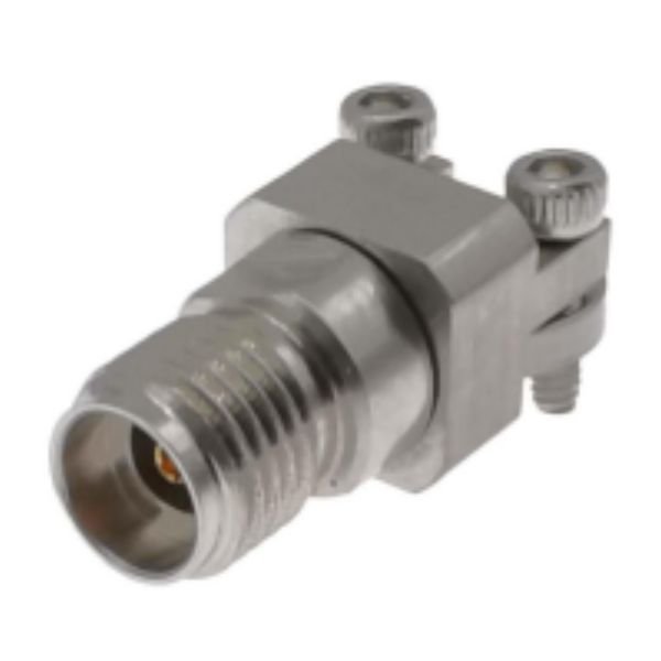
What is an End Launch Connector?
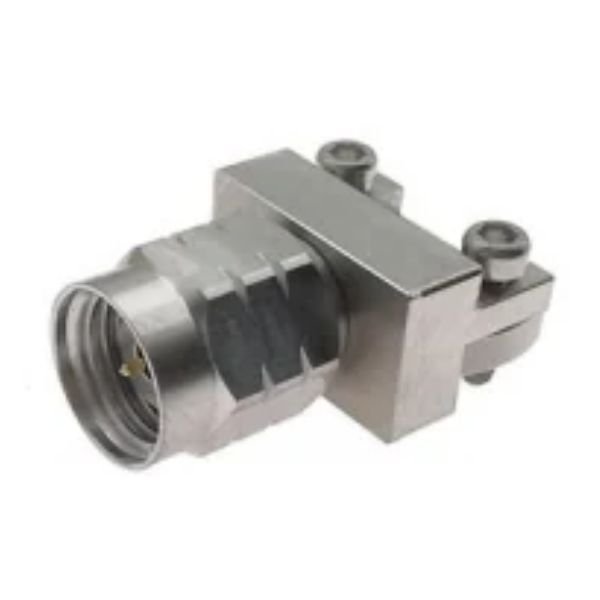
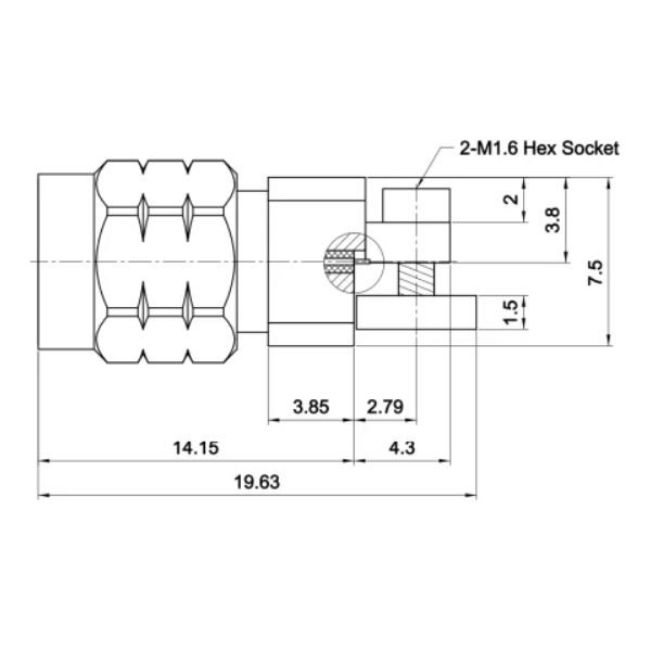
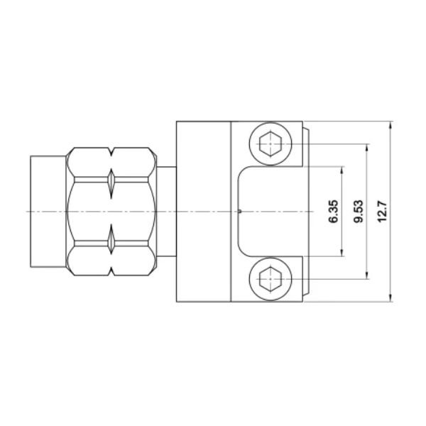
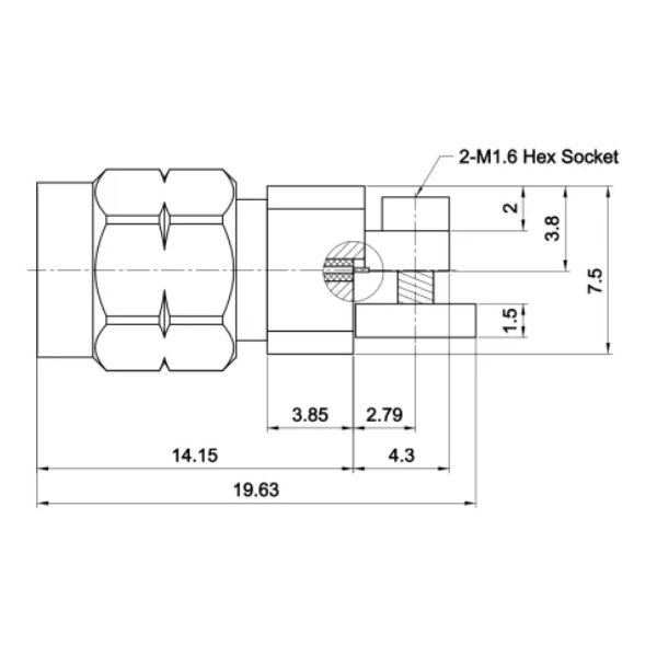
An End Launch Connector is an RF connector designed to mount at the edge of a printed circuit board, creating an electrical transition between a coaxial cable connection and a PCB transmission line. The connector’s center contact interfaces with the board’s signal trace, while its outer body provides a ground connection.
Unlike conventional panel-mounted connectors, End Launch Connectors are specifically designed for board-edge mounting. This configuration reduces the need for additional interconnection hardware and supports compact RF circuit layouts.
End Launch Connectors are particularly useful in high-frequency applications because the transition between the connector and PCB can significantly influence insertion loss, return loss, and signal integrity. Proper connector selection, PCB layout, grounding, and mounting are essential for achieving optimum performance.
Types of End Launch Connectors
1. SMA End Launch Connectors
SMA End Launch Connectors are widely used in RF and microwave applications requiring compact, reliable coaxial-to-PCB connections. They are available in different mounting configurations and frequency ratings, depending on the design.
These connectors are suitable for RF test fixtures, wireless communication equipment, antenna systems, microwave circuits, and laboratory measurement setups.
2. Female End Launch Connectors
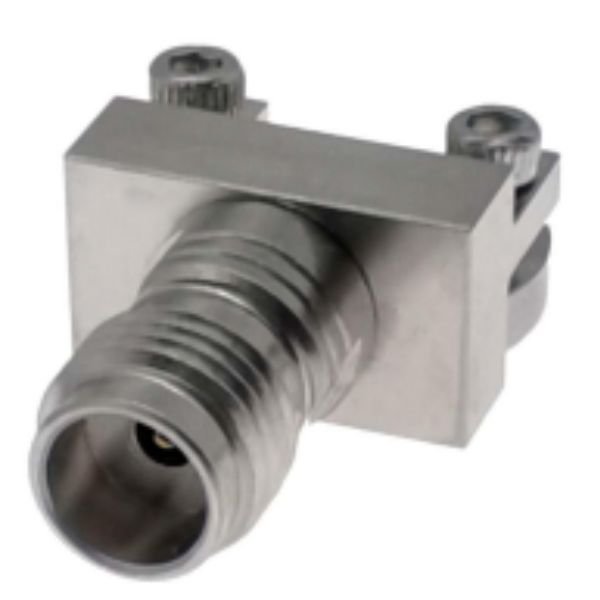
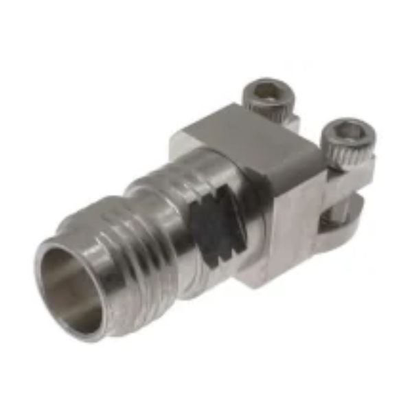
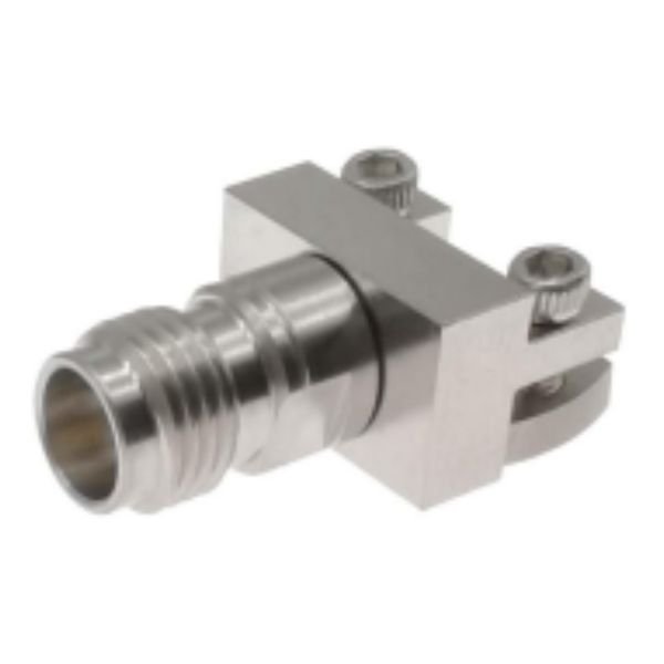
Female End Launch Connectors feature a female coaxial interface and are commonly used to connect test cables or RF equipment to PCB-mounted circuits. They provide convenient access to RF signals while maintaining a compact board-edge configuration.
3. High-Frequency End Launch Connectors
High-frequency End Launch Connectors are precision-designed for microwave circuits that require controlled impedance and low signal reflections. Depending on the connector design, they can support applications operating at several gigahertz and beyond.
4. PCB Edge-Mount RF Connectors
PCB Edge-Mount RF Connectors are designed for direct installation along the edge of a printed circuit board. They provide a compact interface between external RF equipment and internal PCB transmission lines.
5. Custom End Launch Connectors
Custom End Launch Connectors can be selected or developed according to specific PCB thicknesses, connector interfaces, mounting requirements, operating frequencies, and mechanical constraints.
End Launch Connector – Technical Specifications
| Parameter | Specification |
|---|---|
| Product Name | End Launch Connector |
| Connector Interface | SMA / Other Available RF Interfaces |
| Connector Gender | Male / Female, Depending on Model |
| Mounting Style | PCB Edge-Mount |
| Characteristic Impedance | 50 Ohm |
| Frequency Range | Model-Dependent |
| VSWR | Model-Dependent |
| Insertion Loss | Depends on Connector Design and Operating Frequency |
| Contact Material | Model-Dependent Conductive Alloy |
| Plating | Gold or Other Specified Finish |
| Insulator Material | PTFE or Specified Dielectric Material |
| PCB Compatibility | Based on PCB Thickness and Launch Geometry |
| Applications | RF Testing, Microwave Circuits, Antenna Systems, Telecom and PCB Testing |
Technical Specifications
End Launch Connectors are available in multiple configurations. The specifications below describe typical selection parameters; actual values depend on the specific model.
Specification | Details |
|---|---|
Connector Type | End Launch RF Connector |
Connector Interface | SMA and other available RF interfaces |
Mounting Style | PCB Edge-Mount |
Characteristic Impedance | Typically 50 Ohm |
Frequency Range | Model-dependent |
VSWR | Depends on frequency and PCB transition design |
Insertion Loss | Depends on connector design and operating frequency |
Contact Material | Model-dependent conductive alloys |
Plating | Gold or other specified finishes |
Insulator | PTFE or other specified dielectric materials |
PCB Compatibility | Depends on board thickness and launch geometry |
Applications | RF, Microwave, Testing, Communication and Antenna Systems |
For example, SRFS Teleinfra lists an SMA Female End Launch 1.6T connector with a DC–12.4 GHz frequency range, a maximum VSWR of 1.10 over the specified DC–3 GHz range, and a 50 Ohm characteristic impedance. Always verify the individual product datasheet before finalizing your design.
Applications of End Launch Connectors
End Launch Connectors are widely used in applications requiring dependable RF connectivity and efficient PCB integration.
RF and microwave circuit development
Printed circuit board testing
Vector network analyzer (VNA) measurements
Spectrum analyzer test fixtures
Antenna testing and development
Wireless communication equipment
5G and telecommunications systems
Aerospace and defense electronics
Radar and microwave systems
RF amplifier and filter circuits
Satellite communication equipment
Research and development laboratories
Signal generators and measurement instruments
High-frequency electronic modules
Microwave prototyping and validation
Key Performance Factors
Reliable 50 Ohm Impedance Matching
Designed for controlled-impedance RF systems, End Launch Connectors support reliable signal transfer when correctly matched to the PCB transmission line.
Low Signal Reflection
A properly designed connector-to-PCB transition helps reduce unwanted reflections and supports improved return loss across the specified frequency range.
Compact PCB Integration
The edge-mount configuration saves space and enables convenient integration into compact RF modules and test fixtures.
High-Frequency Performance
Available connector configurations support a range of RF and microwave frequencies, depending on the interface, geometry, and manufacturing design.
Durable Construction
Precision-machined metal bodies and suitable contact finishes provide reliable mechanical connections and electrical continuity.
Convenient Testing and Measurement
End Launch Connectors simplify access to PCB circuits during RF characterization, debugging, calibration, and laboratory testing.
Flexible Design Options
Different connector interfaces, PCB mounting arrangements, and frequency ratings support a variety of engineering requirements.
End Launch Connector vs. Standard PCB RF Connector
Feature | End Launch Connector | Standard PCB-Mounted RF Connector |
|---|---|---|
Mounting Position | At the PCB edge | Often mounted on the board surface or panel |
Signal Transition | Coaxial-to-edge transmission line | Depends on connector and PCB layout |
Space Utilization | Suitable for compact board-edge designs | Depends on mounting configuration |
Typical Uses | RF test fixtures, microwave boards, PCB prototypes | RF modules, enclosures and communication equipment |
Performance Factors | Connector geometry, PCB layout and grounding | Connector geometry, PCB layout and grounding |
The appropriate connector depends on PCB geometry, frequency range, mechanical constraints, and the required electrical performance.
Why Choose us
Multiple Connector Options
Our range includes SMA End Launch Connectors and other available configurations to support different interface and installation requirements.
Precision RF Connectivity
We offer End Launch Connectors designed for dependable coaxial-to-PCB connections in RF and microwave applications.
Quality-Focused Product Selection
We emphasize connector specifications, material quality, mounting compatibility, and electrical performance to help customers select suitable components.
Solutions for Diverse Industries
SRFS Teleinfra serves RF and microwave engineering requirements across telecommunications, electronics manufacturing, aerospace, defense, research, and industrial applications.
Frequently Asked Questions
An End Launch Connector connects a coaxial RF interface to a PCB transmission line at the board edge. It is commonly used in microwave circuits, RF test fixtures, antenna development, and high-frequency measurement systems.
A standard SMA connector describes the coaxial interface, while an End Launch Connector describes a mounting configuration intended for PCB-edge connections. An End Launch Connector can itself use an SMA interface.
Most RF End Launch Connectors are designed for 50 Ohm systems, which are commonly used in RF and microwave equipment.
The operating frequency depends on the connector interface, dimensions, construction, and PCB launch design. Some SMA End Launch Connectors support frequencies into the microwave range. Check the specific datasheet for the rated frequency range.
Yes. They are commonly used in RF test fixtures and PCB characterization because they provide convenient coaxial access to board-level transmission lines.
Consider the operating frequency, impedance, PCB thickness, signal trace dimensions, connector interface, mounting requirements, VSWR, insertion loss, and available mechanical clearance.
Yes. Suitable models are used in microwave circuits, filters, amplifiers, antenna systems, and high-frequency test equipment, provided their electrical specifications meet the application requirements.