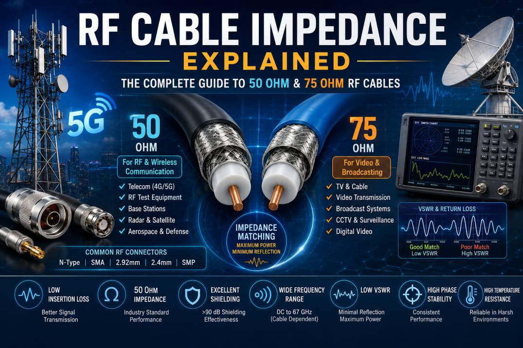
RF cable impedance is one of the most important electrical characteristics to understand when designing, selecting, or installing an RF communication system. Whether the application involves 4G, 5G, wireless communication, radar, satellite systems, test and measurement equipment, broadcasting, or industrial electronics, the correct cable impedance is essential for efficient signal transmission.
In simple terms, RF cable impedance describes the opposition that a high-frequency signal experiences as it travels through a coaxial cable. Unlike ordinary DC resistance, characteristic impedance is determined by the physical construction and electrical properties of the cable.
The most common RF cable impedance values are 50 Ohm and 75 Ohm. Choosing the correct impedance and maintaining impedance matching throughout the complete RF signal path can significantly improve signal quality, reduce reflections, minimize VSWR, and maintain system performance.
What Is RF Cable Impedance?
RF cable impedance, commonly called characteristic impedance or Z0, is the ratio between voltage and current of a travelling electromagnetic wave along a transmission line.
Characteristic impedance is expressed in Ohms (Ω). It is not simply the resistance measured with a multimeter. Instead, it is determined by the geometry of the cable and the dielectric material between the conductors.
For a coaxial cable, characteristic impedance is primarily determined by:
- Diameter of the inner conductor
- Inside diameter of the outer conductor
- Dielectric material
- Dielectric constant
- Cable geometry
- Manufacturing tolerances
For an ideal coaxial cable, characteristic impedance can be approximated by:
Z0 = (60 / √εr) × ln(D/d)
Where:
Z0 = Characteristic impedance
εr = Relative dielectric constant of the insulation
D = Inside diameter of the outer conductor
d = Outside diameter of the inner conductor
This relationship shows why even small changes in conductor dimensions or dielectric properties can affect RF cable impedance.
Why Is RF Cable Impedance Important?
Impedance matching is critical because RF signals behave differently from low-frequency electrical signals. At high frequencies, changes in impedance can cause part of the transmitted signal to be reflected back toward the source.
A properly matched RF system normally maintains the same characteristic impedance across the signal path.
For example:
RF Transmitter → RF Cable → Connector → Filter → Cable Assembly → Antenna
If all components are designed for 50 Ohm operation, maintaining approximately 50 Ohm impedance throughout the RF path helps minimize signal reflections.
Poor impedance matching can result in:
- Signal reflections
- Higher VSWR
- Increased insertion loss
- Reduced transmitted power
- Signal distortion
- Reduced system efficiency
- Measurement errors
- Reduced communication range
- Potential stress on high-power RF equipment
50 Ohm RF Cable
50 Ohm coaxial cable is the most widely used impedance standard for RF communication, wireless infrastructure, test equipment, aerospace, defense, and many microwave applications.
Typical 50 Ohm RF cable applications include:
- 4G and 5G networks
- RF cable assemblies
- Base station equipment
- RRU and antenna connections
- Wireless communication
- RF test equipment
- Vector network analyzers
- Spectrum analyzers
- Radar systems
- Satellite communication
- Aerospace electronics
- Defense communication
- IoT infrastructure
- Industrial RF systems
Many common RF connectors, including SMA, N-Type, TNC, BNC, SMP, SMPM, 2.92 mm, 2.4 mm, and 1.85 mm versions, are available in 50 Ohm configurations.
75 Ohm RF Cable
75 Ohm coaxial cable is commonly associated with video, broadcasting, television, CCTV, and certain broadband communication systems.
Typical applications include:
- Cable television
- Video transmission
- Broadcast systems
- CCTV systems
- Digital video
- Satellite television
- Broadband distribution
- Video surveillance
75 Ohm cables are designed with a different conductor geometry compared with 50 Ohm cables. They should not be selected simply because they appear physically similar to a 50 Ohm cable.
50 Ohm vs 75 Ohm RF Cable
The primary difference between 50 Ohm and 75 Ohm RF cables is their characteristic impedance.
50 Ohm cables are widely used for RF power transmission and wireless communication, while 75 Ohm cables are extensively used for video and broadcast signal transmission.
The correct selection depends on the impedance of the connected equipment.
For example, connecting a 50 Ohm transmitter to a 75 Ohm cable creates an impedance discontinuity. This can increase signal reflections and VSWR.
What Causes Impedance Mismatch?
An impedance mismatch can occur when components in an RF system have different characteristic impedances.
Common causes include:
- Using the wrong RF cable
- Incorrect connector selection
- Poor connector termination
- Incorrect crimping
- Damaged cable
- Improper cable construction
- Poor-quality adapters
- Incorrect PCB transmission-line design
- Changes in conductor dimensions
- Poor shielding construction
- Mechanical deformation
- Excessive bending
- Incorrect termination techniques
Even when the cable itself has the correct impedance, an improperly installed connector can create a significant impedance discontinuity.
RF Cable Impedance and VSWR
Voltage Standing Wave Ratio, commonly abbreviated as VSWR, is an important parameter used to evaluate impedance matching.
When an RF signal encounters an impedance discontinuity, part of the signal is reflected. The combination of forward and reflected waves creates a standing-wave pattern.
VSWR is related to the reflection coefficient Γ by:
VSWR = (1 + |Γ|) / (1 – |Γ|)
A lower VSWR generally indicates better impedance matching.
For many RF applications, engineers aim for very low VSWR because it indicates that most of the signal energy is transferred toward the load rather than reflected toward the source.
RF Cable Impedance and Return Loss
Return loss measures the amount of signal power reflected back toward the source.
Higher return loss generally indicates better impedance matching.
Return loss is expressed in decibels (dB):
Return Loss = -20 log10 |Γ|
A properly designed RF cable assembly can provide excellent return loss across its specified frequency range.
Return loss is particularly important in:
- 5G systems
- Microwave systems
- RF testing
- Satellite communication
- Radar
- Aerospace
- High-frequency instrumentation
How Cable Geometry Determines Impedance
The physical dimensions of a coaxial cable play a major role in determining its characteristic impedance.
A coaxial cable normally contains:
- Center conductor
- Dielectric
- Outer conductor
- Shield
- Protective jacket
The relationship between the center conductor and outer conductor dimensions determines the electromagnetic field distribution inside the cable.
Changing the diameter of the center conductor can change impedance. Similarly, changing the inner diameter of the outer conductor or using a different dielectric material can change the impedance.
This is why precision manufacturing is essential for high-frequency RF cable assemblies.
Role of Dielectric Material
The dielectric material separates the center conductor from the outer conductor and influences the electrical characteristics of the cable.
Common dielectric materials include:
- PTFE
- FEP
- PE
- Foam PE
- Low-loss fluoropolymer materials
- Air or air-spaced structures in specialized designs
The dielectric constant affects propagation velocity, attenuation, and characteristic impedance.
Low-loss dielectric materials are often preferred for high-frequency and low-attenuation RF applications.
RF Cable Impedance and Frequency
Characteristic impedance is generally specified as a nominal value, such as 50 Ohm or 75 Ohm. However, real cables can show frequency-dependent behavior.
At higher frequencies, additional factors become increasingly important, including:
- Skin effect
- Dielectric loss
- Conductor surface quality
- Connector design
- Manufacturing tolerances
- Shield geometry
- Cable bending
- Mechanical deformation
Therefore, selecting a cable solely based on nominal impedance is not sufficient for demanding RF applications.
Frequency range, insertion loss, return loss, power handling, phase stability, shielding effectiveness, and environmental requirements should also be evaluated.
RF Cable Impedance and Insertion Loss
Insertion loss represents the reduction in signal power as the signal travels through a cable or component.
A longer cable normally introduces greater attenuation.
Higher frequencies generally experience greater cable loss because of conductor and dielectric losses.
For this reason, low-loss RF cables are commonly used when long cable runs or high-frequency signals are involved.
Important cable parameters include:
- Characteristic impedance
- Frequency range
- Insertion loss
- Return loss
- VSWR
- Power handling
- Velocity factor
- Shielding effectiveness
- Phase stability
- Operating temperature
Impedance Matching in RF Cable Assemblies
An RF cable assembly includes the cable, connectors, and termination process. The cable impedance must remain controlled throughout the complete assembly.
For example, a 50 Ohm cable should normally be terminated with compatible 50 Ohm connectors when used in a 50 Ohm RF system.
A cable assembly may contain:
- SMA connector
- N-Type connector
- TNC connector
- BNC connector
- 2.92 mm connector
- 2.4 mm connector
- 1.85 mm connector
- SMP connector
- SMPM connector
- MCX connector
- MMCX connector
- QMA connector
Connector selection depends on frequency, mechanical requirements, application, mating interface, power handling, and impedance.
Why Connector Impedance Matters
An RF connector is not simply a mechanical joining device. At high frequencies, it forms part of the transmission line.
Poor connector design or incorrect termination can introduce:
- Impedance discontinuity
- Reflection
- Higher VSWR
- Additional insertion loss
- Reduced return loss
- Signal degradation
High-frequency connectors require carefully controlled dimensions to maintain impedance through the connector interface.
Measuring RF Cable Impedance
Several techniques can be used to evaluate RF cable performance.
Time Domain Reflectometry
TDR can identify impedance changes along a transmission line. It is useful for detecting:
- Connector discontinuities
- Cable damage
- Incorrect termination
- Manufacturing defects
- Impedance variations
Vector Network Analyzer
A Vector Network Analyzer, or VNA, is widely used for measuring RF cable performance.
A VNA can measure parameters such as:
- S11
- S21
- Return loss
- Insertion loss
- VSWR
- Phase
- Group delay
VNA measurements are particularly useful for high-frequency cable assemblies.
Common RF Cable Impedance Standards
Some commonly encountered RF transmission-line impedance values include:
- 50 Ohm
- 75 Ohm
- 93 Ohm in specialized applications
- Other custom impedances for specific systems
50 Ohm and 75 Ohm remain the dominant coaxial cable impedance standards for modern commercial and industrial applications.
How to Select the Correct RF Cable Impedance
Selecting the correct RF cable requires understanding the equipment connected to both ends of the cable.
Consider the following factors:
1. Equipment Impedance
Check the impedance specification of the transmitter, receiver, antenna, test equipment, or RF module.
2. Frequency Range
Choose a cable designed for the required operating frequency.
3. Cable Length
Longer cables generally introduce more attenuation, so low-loss cable may be required.
4. Power Level
High-power applications require cables with suitable power-handling capability.
5. Connector Type
Select compatible connectors according to the equipment interface.
6. VSWR Requirement
For demanding RF systems, select a cable assembly with appropriate VSWR and return-loss performance.
7. Environmental Conditions
Outdoor telecom systems may require UV resistance, waterproofing, temperature resistance, and robust jacketing.
8. Mechanical Requirements
Consider bending radius, flexibility, vibration, installation space, and repeated mating requirements.
RF Cable Impedance in 4G and 5G Networks
Modern telecom networks depend heavily on controlled-impedance RF cable assemblies.
In 4G and 5G infrastructure, RF cables may connect:
- Remote Radio Units
- Baseband equipment
- Antennas
- Filters
- Combiners
- Splitters
- Duplexers
- RF distribution systems
- Test equipment
At higher 5G frequencies, impedance control becomes increasingly important because RF losses and reflections become more significant.
Precision cable assemblies with controlled impedance help maintain reliable RF performance between active equipment and antenna systems.
RF Cable Impedance in Test and Measurement
Test and measurement systems require highly controlled RF transmission paths.
A cable used with a VNA or spectrum analyzer can directly influence measurement accuracy.
High-performance test cables are therefore designed for:
- Low VSWR
- High return loss
- Low insertion loss
- Stable phase
- High shielding effectiveness
- Excellent connector repeatability
- Mechanical durability
For precision measurements, calibration and cable stability are especially important.
Common RF Cable Impedance Mistakes
Using 75 Ohm Cable in a 50 Ohm RF System
This can create impedance mismatch and additional reflections.
Mixing Different Connector Impedances
A physically compatible connector may still have an electrically incompatible impedance.
Ignoring Connector Quality
The cable may have excellent specifications, but poor connectors can reduce overall performance.
Excessive Cable Bending
Sharp bends can alter cable geometry and cause impedance changes.
Using Damaged Cable
Crushing, deformation, or improper installation can affect the internal structure of coaxial cable.
Ignoring Frequency
A cable may perform well at one frequency but have unacceptable loss or VSWR at a much higher frequency.
RF Cable Impedance and Signal Reflection
Signal reflection occurs when the impedance of the transmission line changes.
For example, consider a 50 Ohm RF source connected through a 50 Ohm cable to a 50 Ohm load. The signal sees a consistent impedance and minimal reflection occurs.
If the cable suddenly changes to 75 Ohm, the signal encounters a discontinuity. A portion of the energy is reflected.
This reflected energy can interfere with the forward signal and reduce overall system efficiency.
Advantages of Proper RF Impedance Matching
Maintaining proper impedance matching provides several benefits:
- Lower signal reflection
- Lower VSWR
- Better return loss
- Improved power transfer
- Reduced transmission losses
- More reliable RF measurements
- Better system efficiency
- Improved communication performance
- Greater signal integrity
- More predictable RF behavior
RF Cable Impedance: Key Takeaways
RF cable impedance is a fundamental specification in RF and microwave engineering. The most common values are 50 Ohm and 75 Ohm, with 50 Ohm widely used for wireless, telecom, test, aerospace, defense, and microwave applications, while 75 Ohm is common in video and broadcast systems.
Impedance is determined by cable geometry and dielectric properties rather than simple DC resistance. Maintaining the correct impedance across cables, connectors, adapters, filters, antennas, and equipment helps reduce signal reflections and maintain low VSWR.
For demanding RF applications, cable selection should consider impedance together with frequency, insertion loss, return loss, power handling, shielding, phase stability, environmental conditions, and connector performance.
Why Choose SRFS Teleinfra for RF Cable Solutions?
SRFS Teleinfra provides RF and telecom cable solutions designed for demanding communication and infrastructure applications. The product range includes RF cables, RF cable assemblies, connectors, clamps, mounting accessories, weatherproofing solutions, grounding kits, and other RF infrastructure products.
For applications requiring controlled impedance, low-loss transmission, reliable connectors, and consistent RF performance, selecting the correct cable construction and connector configuration is essential.
Frequently Asked Questions About RF Cable Impedance
What is RF cable impedance?
RF cable impedance is the characteristic impedance presented by a transmission line to a travelling RF signal. It is normally expressed in Ohms and is determined primarily by conductor geometry and dielectric properties.
What is the most common RF cable impedance?
50 Ohm is one of the most widely used impedance standards for RF, wireless, telecom, microwave, aerospace, defense, and test applications.
What is the difference between 50 Ohm and 75 Ohm cable?
50 Ohm cable is widely used for RF power and wireless communication systems, while 75 Ohm cable is commonly used for video, broadcasting, television, and related applications.
Can I use a 75 Ohm cable in a 50 Ohm system?
It is technically possible, but it introduces an impedance mismatch that can increase signal reflections and VSWR. A properly matched 50 Ohm cable is normally preferred for a 50 Ohm system.
Does cable length affect impedance?
Cable length does not normally change the nominal characteristic impedance of a properly manufactured cable, but cable length affects attenuation, phase delay, and the overall transmission-line behavior of the system.
How is RF cable impedance measured?
RF cable impedance and performance can be evaluated using equipment such as a Vector Network Analyzer or Time Domain Reflectometer. A VNA can measure VSWR, return loss, insertion loss, and other RF parameters.
Does RF cable impedance affect signal loss?
Impedance mismatch can cause reflections and reduce effective power transfer. Cable construction, conductor material, dielectric material, length, and frequency also strongly influence insertion loss.
Why is 50 Ohm used in RF systems?
50 Ohm became widely adopted as a practical compromise between power-handling capability and attenuation for coaxial transmission systems. It is now a major standard throughout RF and microwave engineering.
Why is 75 Ohm common for video?
75 Ohm became a widely adopted standard for video and broadcast transmission because of its electrical characteristics and compatibility with established video transmission infrastructure.
Do RF connectors also have impedance?
Yes. RF connectors have electrical characteristics and can be designed for specific impedance standards, including 50 Ohm and 75 Ohm. Connector geometry is important for maintaining impedance through the interface.
What is the relationship between impedance and VSWR?
When a load impedance does not match the transmission-line impedance, some RF energy is reflected. The resulting forward and reflected waves produce VSWR. Better impedance matching generally produces lower VSWR.
What should I consider when buying an RF cable?
Consider characteristic impedance, frequency range, cable length, insertion loss, return loss, VSWR, power handling, shielding effectiveness, flexibility, environmental requirements, connector type, and application-specific requirements.
Conclusion
Understanding RF cable impedance is essential for designing reliable and efficient RF systems. A correctly selected cable provides the required characteristic impedance while supporting the necessary frequency, power, mechanical, environmental, and signal-integrity requirements.
For most RF and telecom applications, 50 Ohm is the primary impedance standard, while 75 Ohm is widely used for video and broadcast applications. However, impedance alone should never be the only selection criterion. Cable loss, VSWR, return loss, connector quality, shielding, phase stability, and operating environment must also be considered.
Choosing a properly engineered RF cable assembly and maintaining impedance continuity throughout the complete RF signal chain can significantly improve signal integrity, power transfer, measurement accuracy, and overall system reliability.