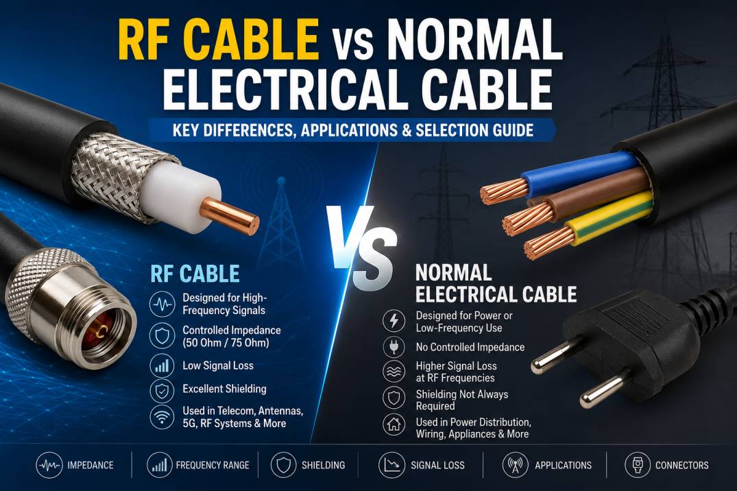
RF cables and normal electrical cables may look similar at first glance, but they are designed to perform very different functions. An RF cable is engineered to carry high-frequency radio-frequency signals with controlled impedance, low signal loss, effective shielding and stable electrical performance. A normal electrical cable is primarily designed to carry electrical power or low-frequency electrical signals from one point to another.
Understanding the difference between an RF cable and a normal electrical cable is important when designing telecommunications systems, 4G and 5G networks, wireless communication equipment, RF testing systems, antennas, broadcast systems, industrial equipment and electronic devices. Using the wrong type of cable can result in signal loss, electromagnetic interference, poor transmission quality, heating, unreliable operation or even equipment damage.
This comprehensive guide explains the differences between RF cable and normal electrical cable, including construction, impedance, shielding, frequency range, signal loss, applications, materials, connectors and selection criteria.
What Is an RF Cable?
An RF cable, or Radio Frequency cable, is a specialized transmission cable designed to carry radio-frequency and microwave signals between electronic components and systems.
RF cables are commonly used for transmitting signals between antennas, radios, amplifiers, transmitters, receivers, test instruments, filters, splitters, combiners and other RF equipment.
Unlike ordinary electrical cables, RF cables are manufactured with controlled electrical characteristics. One of their most important properties is controlled characteristic impedance, commonly 50 Ohm or 75 Ohm.
Common RF cable types include coaxial cables, flexible RF cables, semi-rigid cables, semi-flexible cables, low-loss cables, high-frequency cables and specialized phase-stable cables.
What Is a Normal Electrical Cable?
A normal electrical cable is generally designed to transport electrical power or low-frequency electrical signals. These cables are widely used in residential, commercial, industrial and electrical installations.
Examples include power cables, control cables, wiring cables, battery cables and general-purpose electrical conductors.
The primary design considerations for many electrical cables are conductor size, voltage rating, current-carrying capacity, insulation, temperature rating, mechanical strength and safety.
Unlike RF cables, normal electrical cables are generally not designed around controlled RF impedance or high-frequency transmission performance.
RF Cable vs Normal Electrical Cable: Basic Difference
The fundamental difference is the purpose for which each cable is engineered.
An RF cable is optimized for transmitting electromagnetic signals at radio and microwave frequencies, while a normal electrical cable is generally optimized for carrying electrical power or low-frequency electrical signals.
An RF cable must maintain predictable impedance and minimize signal reflection and attenuation. A conventional electrical cable primarily focuses on safely carrying the required current and voltage.
RF Cable vs Normal Electrical Cable Comparison
1. Primary Purpose
RF cables are designed for high-frequency signal transmission.
Normal electrical cables are primarily designed for power distribution, electrical connections or low-frequency signal transmission.
2. Frequency Range
RF cables can operate from relatively low frequencies into the MHz and GHz ranges depending on their construction and specifications.
Normal electrical cables are generally used for DC, 50/60 Hz AC power or relatively low-frequency electrical signals.
3. Characteristic Impedance
Characteristic impedance is one of the most important specifications of an RF cable.
Common RF impedance values include:
- 50 Ohm
- 75 Ohm
A 50 Ohm RF cable is widely used in wireless communication, RF testing, cellular infrastructure, aerospace and defense applications.
A 75 Ohm RF cable is commonly used in video, television, broadcast and certain broadband applications.
Normal electrical cables generally do not use controlled characteristic impedance as a primary design requirement.
4. Construction
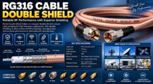
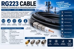
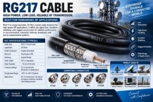
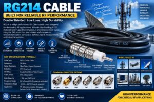
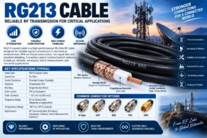
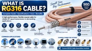
Most RF cables use a coaxial structure consisting of:
- Center conductor
- Dielectric insulator
- Conductive shield
- Outer jacket
This geometry helps maintain controlled impedance and provides protection against electromagnetic interference.
Normal electrical cables may contain one or more conductors surrounded by insulation and an outer protective jacket. Their construction depends mainly on voltage, current, mechanical and environmental requirements.
5. Shielding
RF cables normally require effective shielding to prevent external electromagnetic interference from entering the cable and to prevent RF energy from escaping.
Common RF shielding structures include:
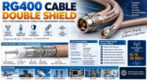
- Braided shields
- Foil shields
- Dual shields
- Triple shields
- Corrugated conductors
- Tubular outer conductors
Normal electrical cables may be shielded when required, but shielding is not necessarily part of their basic construction.
6. Signal Loss
RF signal loss is a critical consideration because attenuation increases with frequency.
RF cables are engineered to minimize insertion loss and maintain signal integrity over their specified frequency range.
Normal electrical cables are not generally optimized for low RF insertion loss. Using them for high-frequency RF transmission can result in significant attenuation and signal degradation.
7. Electromagnetic Interference
RF systems can be highly sensitive to electromagnetic interference.
RF cables use shielding and controlled geometry to reduce unwanted interference and electromagnetic coupling.
Normal electrical cables may generate or receive electromagnetic interference depending on their construction and application.
8. Reflections and VSWR
RF systems are highly sensitive to impedance mismatches.
A mismatch between the RF cable, connector and equipment can cause signal reflections. These reflections can be represented through parameters such as VSWR and return loss.
RF cables are designed to maintain controlled impedance and minimize reflections.
Normal electrical cables are generally not specified for VSWR or return loss at RF operating frequencies.
RF Cable Construction in Detail
A typical coaxial RF cable contains four major components.
Center Conductor
The center conductor carries the RF signal.
Common conductor materials include:
- Copper
- Silver-plated copper
- Copper-clad steel
- Tinned copper
The conductor size and material influence attenuation, flexibility, conductivity and frequency performance.
Dielectric
The dielectric separates the center conductor from the outer shield.
Common dielectric materials include:
- PTFE
- FEP
- PE
- Foam polyethylene
- Low-loss fluoropolymer materials
The dielectric affects characteristic impedance, velocity factor, dielectric loss and maximum operating temperature.
Shield
The shield provides electromagnetic protection and helps establish the cable’s transmission-line structure.
RF cables may use copper braid, aluminum foil, silver-plated shielding or combinations of foil and braid.
Outer Jacket
The jacket protects the cable against mechanical damage, moisture, chemicals, UV exposure and environmental conditions.
Depending on the application, RF cable jackets may be made from PVC, PE, FEP or other specialized materials.
Why RF Cable Has Controlled Impedance
Controlled impedance is essential for efficient RF transmission.
For example, if a transmitter, RF cable and antenna are designed for 50 Ohm operation, using a properly matched 50 Ohm cable helps minimize reflections.
An impedance mismatch can cause:
- Increased reflected power
- Higher VSWR
- Reduced transmitted power
- Signal distortion
- Increased insertion loss
- Potential stress on RF transmit equipment
This is one of the major reasons why ordinary electrical cable should not be substituted for RF cable in professional RF systems.
RF Cable Frequency Performance
Different RF cables support different frequency ranges.
Some general-purpose coaxial cables may operate into the hundreds of MHz or several GHz, while specialized microwave cables can operate at tens of GHz or higher.
High-frequency RF cables are used in:
- 5G systems
- Microwave communication
- Radar
- Satellite communication
- Aerospace systems
- RF laboratories
- Semiconductor testing
- Wireless test equipment
The actual maximum frequency depends on cable construction, connector design, dimensions, materials, manufacturing tolerances and installation quality.
RF Cable Attenuation
Attenuation describes the amount of signal power lost as an RF signal travels through a cable.
Cable attenuation is usually expressed in dB per unit length, such as dB/m or dB/100 m.
Attenuation generally increases with:
- Frequency
- Cable length
- Conductor resistance
- Dielectric loss
- Poor connector performance
- Bends and mechanical damage
For long-distance RF transmission, low-loss RF cable is often preferred.
Why Normal Electrical Cable Is Not Suitable for RF Signals
Using ordinary electrical cable for RF transmission can create several problems.
High Signal Loss
The cable may not have the conductor and dielectric characteristics required for efficient high-frequency transmission.
Impedance Mismatch
The cable may not provide the required 50 Ohm or 75 Ohm impedance.
Increased Reflections
Impedance discontinuities can increase signal reflections and degrade system performance.
Poor Shielding
Unshielded or inadequately shielded electrical cable can pick up interference from nearby electronic equipment.
Electromagnetic Radiation
An unsuitable cable can unintentionally radiate RF energy and create electromagnetic compatibility problems.
Unstable RF Performance
Cable characteristics can change significantly with frequency, temperature, bending and installation conditions.
RF Cable vs Electrical Cable: Technical Comparison
| Feature | RF Cable | Normal Electrical Cable |
|---|---|---|
| Primary application | RF signal transmission | Power/electrical connection |
| Typical frequency | MHz to GHz and beyond | DC, 50/60 Hz and low-frequency applications |
| Controlled impedance | Yes | Usually not a primary requirement |
| Common impedance | 50 Ohm, 75 Ohm | Not normally specified |
| Shielding | Common and important | Application dependent |
| VSWR specification | Common | Generally not specified |
| Return loss | Important | Generally not a primary parameter |
| RF attenuation | Critical | Usually not specified |
| EMI control | Important | Application dependent |
| Typical structure | Coaxial/transmission line | Single/multiconductor |
| RF connectors | SMA, N, BNC, TNC, MCX, MMCX, SMP, etc. | Terminals, lugs, plugs and electrical connectors |
| Typical applications | Telecom, antennas, RF testing, radar | Power, control, electrical distribution |
Common Types of RF Cables
Flexible RF Cable
Flexible RF cables are designed for applications requiring repeated movement or easier installation.
They are commonly used in:
- Wireless equipment
- Antenna connections
- Test equipment
- Telecom systems
- RF modules
Low-Loss RF Cable
Low-loss RF cables are designed to reduce attenuation over longer cable runs.
They are frequently used in:
- Cellular networks
- Base stations
- Distributed antenna systems
- Outdoor RF installations
- Wireless infrastructure
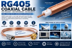
Semi-Rigid RF Cable
Semi-rigid cables use a solid outer conductor and provide excellent shielding and stable RF characteristics.
They are common in:
- Microwave systems
- Aerospace electronics
- Defense equipment
- Laboratory equipment
- High-frequency instrumentation
Semi-Flexible RF Cable
Semi-flexible cables provide a balance between flexibility and RF performance.
They are useful where routing flexibility is required without sacrificing the advantages of high-performance RF transmission.
Phase-Stable RF Cable
Phase-stable cables are designed to maintain consistent electrical phase characteristics when subjected to movement or temperature changes.
They are particularly useful in:
- Test and measurement
- Radar
- Phased-array systems
- Aerospace
- Defense
- High-frequency instrumentation
Common RF Cable Connectors
RF cables are commonly terminated with specialized RF connectors such as:
- SMA
- N Type
- BNC
- TNC
- SMB
- SMC
- MCX
- MMCX
- QMA
- Mini DIN
- 2.4 mm
- 2.92 mm
- 1.85 mm
- SMP
- SMPM
- U.FL/IPEX
Connector selection should match the cable impedance, frequency range, mechanical requirements and equipment interface.
RF Cable Applications
RF cables are widely used across modern communication and electronic systems.
Telecom Networks
RF cables connect antennas, radios, remote radio units, combiners and other RF infrastructure.
4G and 5G Networks
RF cable assemblies are used for connecting RF equipment and antennas in cellular infrastructure.
Antenna Systems
RF cables provide the transmission path between antennas and transmit/receive equipment.
In-Building Solutions
RF cable assemblies are widely used in distributed antenna systems and indoor wireless coverage installations.
Satellite Communication
RF and microwave cables are used between antennas, transceivers, amplifiers and other satellite communication equipment.
Radar
Radar systems require carefully controlled RF transmission paths to maintain signal integrity and phase stability.
Aerospace and Defense
High-performance RF cables are used in avionics, radar, electronic warfare, communication systems and test equipment.
RF Testing and Measurement
RF test cables connect signal generators, spectrum analyzers, network analyzers and other measurement equipment.
Broadcast Systems
RF cables are used for transmitting radio and television signals between transmitters, antennas and associated equipment.
Applications of Normal Electrical Cables
Normal electrical cables are primarily used for:
- Power distribution
- Electrical panels
- Building wiring
- Motors
- Lighting
- Industrial machinery
- Battery connections
- Control systems
- Low-frequency instrumentation
- Electrical appliances
These applications have different requirements from RF signal transmission.
How to Choose the Right RF Cable
Selecting the correct RF cable requires consideration of several parameters.
Frequency Range
Choose a cable rated for the highest frequency required by the system.
Characteristic Impedance
Verify whether the system requires 50 Ohm or 75 Ohm impedance.
Cable Length
Longer cables generally produce greater attenuation, so low-loss cable may be required for long runs.
Insertion Loss
Compare attenuation at the actual operating frequency rather than relying only on a general cable specification.
Shielding Effectiveness
For high-density telecom and RF environments, high shielding effectiveness can help reduce electromagnetic interference.
Power Handling
Check the cable’s RF power-handling capability, especially for transmitter applications.
Operating Temperature
Select a cable suitable for the expected environmental temperature range.
Flexibility
Flexible cable is preferable where frequent movement or tight routing is required, while semi-rigid cable may be better where stable mechanical installation is more important.
Connector Compatibility
Ensure that the cable connectors match the equipment interface and frequency requirements.
Environmental Conditions
Outdoor installations may require UV-resistant, weather-resistant and moisture-resistant cable construction.
RF Cable Assembly vs Ordinary Wire Assembly
An RF cable assembly is more than a cable with connectors attached to both ends.
A professional RF cable assembly requires:
- Correct cable selection
- Correct impedance
- Compatible connectors
- Accurate connector termination
- Proper stripping dimensions
- Controlled assembly process
- Low VSWR
- Low insertion loss
- Good return loss
- Mechanical reliability
- Proper testing
This is particularly important in high-frequency systems where small manufacturing errors can significantly affect performance.
Importance of RF Cable Quality
Cable quality can directly influence overall RF system performance.
A poor-quality RF cable may cause:
- Excessive insertion loss
- High VSWR
- Poor return loss
- Connector failure
- EMI problems
- Reduced communication range
- Signal instability
- Reduced system efficiency
High-quality RF cables manufactured using appropriate materials and controlled processes can provide more predictable performance.
RF Cable vs Normal Electrical Cable: Which One Should You Use?
Use an RF cable when transmitting radio-frequency or microwave signals between RF components.
Use a normal electrical cable when the application involves power distribution, electrical connections or low-frequency control signals and does not require controlled RF transmission characteristics.
For example, an antenna connected to a radio should generally use a suitable RF coaxial cable rather than ordinary electrical wire.
Similarly, connecting a DC power supply to equipment generally requires an appropriately rated electrical cable rather than an RF cable.
Can RF Cable Carry Electrical Power?
Yes, an RF cable can carry DC power in many applications, provided its conductor, insulation, connector and current ratings are suitable.
Some RF systems use coaxial cables to carry DC power together with RF signals. This is commonly known as DC biasing or DC power injection.
However, the cable should always be selected according to the required voltage, current, frequency and environmental conditions.
Can Normal Electrical Cable Carry RF Signals?
In some experimental or specialized situations, electrical conductors can carry RF energy. However, ordinary electrical cable is generally not a suitable replacement for properly designed RF transmission cable.
At higher frequencies, impedance, geometry, shielding, dielectric properties and connector transitions become increasingly important.
For professional RF systems, a purpose-designed RF cable is normally the appropriate choice.
RF Cable Selection for 4G and 5G Networks
4G and 5G infrastructure can operate across multiple frequency bands, making cable selection especially important.
For cellular infrastructure, engineers may consider:
- Frequency range
- Cable attenuation
- Connector type
- PIM performance
- Shielding
- Power handling
- Cable length
- Outdoor durability
- Temperature rating
- Bend radius
- Mechanical strength
Low-loss coaxial cable and high-quality RF cable assemblies are commonly selected for antenna feeder and equipment interconnection applications.
Low PIM RF Cable Considerations
Passive intermodulation, commonly known as PIM, is an important consideration in modern cellular networks.
Unwanted nonlinear behavior at connectors, cables or passive components can generate intermodulation products that interfere with receiving frequencies.
For demanding cellular applications, low-PIM cable assemblies and compatible low-PIM connectors are preferred.
Proper connector installation and clean mechanical interfaces are also essential for maintaining low PIM performance.
Environmental Protection for Outdoor RF Cable
Outdoor RF cable installations may be exposed to:
- Rain
- Moisture
- UV radiation
- Dust
- Temperature fluctuations
- Wind
- Chemicals
- Mechanical stress
Weatherproofing accessories such as sealing tapes, self-amalgamating tape and appropriate cable protection systems can help protect outdoor RF connections.
Proper installation is just as important as cable selection.
Common Mistakes When Selecting RF Cable
Choosing Cable Solely by Diameter
A larger cable is not automatically better. Frequency range, attenuation, impedance and power handling must also be considered.
Ignoring Connector Frequency Rating
A high-performance cable paired with an unsuitable connector can limit the performance of the entire assembly.
Using 75 Ohm Cable in a 50 Ohm System
This can create impedance mismatch and signal reflections.
Ignoring Cable Length
Even a high-quality cable can introduce significant loss when used over long distances.
Excessive Bending
Sharp bends can change cable geometry and degrade RF performance.
Poor Connector Installation
Incorrect stripping, crimping or soldering can increase insertion loss and VSWR.
Ignoring Environmental Conditions
Outdoor systems require cable and connector assemblies designed for the actual environmental conditions.
Benefits of Using High-Quality RF Cable
High-quality RF cables can provide:
- Low insertion loss
- Stable characteristic impedance
- Better shielding
- Lower signal reflection
- Improved VSWR
- Reliable connector performance
- Better electromagnetic compatibility
- Higher system reliability
- Consistent high-frequency performance
- Longer service life
Why RF Cable Is Important in Modern Communication
Wireless communication depends on reliable RF signal transmission.
Modern technologies such as 4G, 5G, Wi-Fi, satellite communication, radar, IoT and advanced wireless systems operate at increasingly higher frequencies. At these frequencies, cable construction and transmission characteristics become critical.
A cable that performs adequately at low frequencies may not perform effectively at several GHz.
Therefore, RF cable selection should be treated as an important part of the overall RF system design rather than as a simple wiring decision.
RF Cable Manufacturer and Supplier in India
SRFS Teleinfra provides RF and telecom connectivity solutions for communication, wireless infrastructure and RF applications. Its product range can include RF cables, cable assemblies, RF connectors, adapters, clamps, grounding accessories and other telecom infrastructure products.
For professional RF applications, cable selection should always be based on the required frequency, impedance, attenuation, connector interface, power level and environmental conditions.
Conclusion
RF cable and normal electrical cable are designed for fundamentally different purposes. Normal electrical cables are primarily intended for carrying electrical power or low-frequency signals, whereas RF cables are engineered for controlled high-frequency signal transmission.
The most important differences include characteristic impedance, frequency capability, shielding, attenuation, VSWR, return loss, construction and connector compatibility.
For telecom, 4G, 5G, antenna, radar, satellite, aerospace, defense and RF testing applications, choosing a properly specified RF cable is essential for maintaining signal integrity and system reliability.
The correct RF cable should always be selected according to frequency range, impedance, insertion loss, cable length, power handling, shielding, connector type and environmental requirements.
Frequently Asked Questions
What is the main difference between RF cable and normal electrical cable?
RF cable is designed to transmit high-frequency radio signals with controlled impedance and low signal loss, while normal electrical cable is primarily designed for power or low-frequency electrical applications.
Can I use normal electrical wire for RF signals?
Although electrical wire can conduct RF energy, ordinary electrical wire is generally unsuitable for professional RF transmission because it does not provide the controlled impedance, shielding and predictable high-frequency characteristics required by RF systems.
Is RF cable always coaxial?
No. Coaxial cable is the most common RF cable construction, but RF transmission can also use specialized cable structures and transmission lines depending on the application.
What impedance is commonly used for RF cables?
The two most common RF cable impedance values are 50 Ohm and 75 Ohm. The correct impedance depends on the equipment and system architecture.
Why is 50 Ohm RF cable widely used?
50 Ohm systems provide a widely adopted standard for many wireless, telecommunications, microwave, aerospace, defense and RF test applications.
Why is shielding important in RF cable?
Shielding reduces electromagnetic interference and helps prevent unwanted RF energy from entering or escaping the transmission path.
Does RF cable have signal loss?
Yes. All practical RF cables have some insertion loss. The amount depends on frequency, cable construction, length, conductor material, dielectric material and installation conditions.
Can RF cable carry DC power?
Yes. Some RF coaxial cables can carry DC power when their conductor, insulation and connectors are appropriately rated.
What happens if I use the wrong RF cable?
The system may experience excessive signal loss, impedance mismatch, high VSWR, poor return loss, interference, reduced communication range or unreliable operation.
How do I select an RF cable?
Consider frequency, impedance, insertion loss, cable length, connector type, power handling, shielding, flexibility, operating temperature and environmental conditions.
What RF cable is suitable for 5G applications?
The appropriate cable depends on the 5G frequency band, cable length, attenuation requirement, connector interface, power level, PIM requirement and installation environment. Low-loss and low-PIM RF cable assemblies are commonly considered for demanding cellular infrastructure.
What is the difference between RF cable and coaxial cable?
Coaxial cable is a physical cable construction consisting of a center conductor, dielectric, shield and outer jacket. RF cable describes cable intended for radio-frequency transmission. Most RF cables used in telecom and wireless systems are coaxial.