
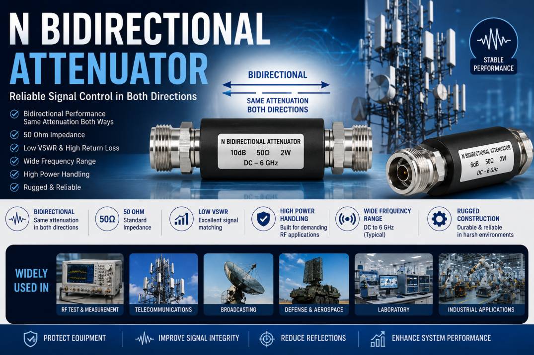
An N Bidirectional Attenuator is a passive RF component designed to reduce signal power by a specific amount while maintaining impedance matching and stable signal transmission in both directions. It uses N-Type RF connectors and is commonly used in wireless communication, RF testing, telecom infrastructure, antenna systems, broadcast networks, radar, and other high-frequency applications.
Unlike directional components that are designed to operate primarily in one signal path, a bidirectional attenuator provides the same nominal attenuation regardless of which port is used as the input. This makes it particularly useful in RF systems where signal direction can change or where equipment needs a reliable impedance-matched interface.
Most N-Type bidirectional attenuators are designed for 50 Ohm RF systems and are available in different attenuation values such as 1 dB, 3 dB, 6 dB, 10 dB, 20 dB, and higher values. Depending on the design, they can also support significant RF power levels and wide frequency ranges.
What Is an N Bidirectional Attenuator?
An N Bidirectional Attenuator is a fixed RF attenuator equipped with N-Type connectors on both ends. Its primary function is to decrease the amplitude or power level of an RF signal by a predetermined amount while maintaining a controlled impedance environment.
The term “N” refers to the N-Type coaxial connector interface, while “bidirectional” means the attenuator can be used in either direction.
For example, a 10 dB N Bidirectional Attenuator provides approximately 10 dB of attenuation when RF power enters from either port. This makes installation flexible and eliminates the need to determine a specific input and output side.
These attenuators are passive devices, meaning they do not require an external power supply to perform their attenuation function.
How Does an N Bidirectional Attenuator Work?
An N Bidirectional Attenuator uses resistive or other passive RF network elements to reduce signal power while maintaining the desired characteristic impedance.
When an RF signal enters one port, a portion of the signal power is dissipated within the attenuator. The remaining signal continues through the output port at a lower power level.
Because the internal attenuation network is designed symmetrically, the same nominal attenuation is available in the reverse direction.
For example, if a system uses a 6 dB bidirectional attenuator:
Input signal → 6 dB attenuation → Reduced output signal
The same behavior occurs when the signal direction is reversed.
This makes bidirectional attenuators useful for systems with changing signal paths, test setups, duplex communication systems, and RF equipment interfaces.
Why Is an N Bidirectional Attenuator Used?
RF systems often operate with signals that are stronger than the connected equipment can safely or accurately handle. Excessive RF power can cause receiver compression, measurement errors, nonlinear behavior, or even damage to sensitive equipment.
An N Bidirectional Attenuator helps control these signal levels.
Major purposes include:
- Reducing excessive RF signal power
- Protecting sensitive RF equipment
- Improving impedance matching
- Reducing signal reflections
- Improving measurement accuracy
- Controlling receiver input levels
- Matching different RF equipment interfaces
- Improving system stability
- Reducing unwanted signal amplitude
- Creating controlled RF test conditions
Key Features of N Bidirectional Attenuators
A high-quality N Bidirectional Attenuator typically provides several important electrical and mechanical characteristics.
Bidirectional Operation
The attenuator can be connected in either direction without changing its nominal attenuation value.
50 Ohm Impedance
Most N-Type RF attenuators are designed for 50 Ohm systems used in telecommunications, wireless communication, RF testing, and antenna applications.
Fixed Attenuation
The attenuation value remains fixed and is normally selected according to the requirements of the RF system.
Low VSWR
A properly designed attenuator maintains good impedance matching and helps reduce signal reflections.
High Return Loss
Good return loss indicates that less RF energy is reflected back toward the source.
Wide Frequency Range
Depending on construction and connector design, N-Type attenuators can operate across a broad RF frequency range.
Rugged Construction
N-Type connectors are mechanically robust and suitable for demanding industrial and outdoor applications.
No External Power Required
As a passive component, the attenuator does not require electrical power to perform its basic attenuation function.
Common Attenuation Values
N Bidirectional Attenuators are available in several standard attenuation levels.
Common values include:
- 1 dB
- 2 dB
- 3 dB
- 5 dB
- 6 dB
- 10 dB
- 15 dB
- 20 dB
- 30 dB
- 40 dB
The correct attenuation value depends on the required RF signal level.
For example, a 3 dB attenuator provides a smaller reduction than a 10 dB attenuator, while a 20 dB attenuator provides substantially greater signal reduction.
Understanding Attenuation in dB
Attenuation is normally specified in decibels (dB).
For power:
Pout/Pin = 10^(-A/10)
Where:
- A = attenuation in dB
- Pin = input power
- Pout = output power
For example, a 10 dB attenuator allows approximately 10% of the input power to reach the output, with the remaining power dissipated within the attenuator.
This relationship is important when selecting an attenuator for a high-power RF application.
N Bidirectional Attenuator Connector Types
N-Type attenuators can be supplied with different connector configurations.
N Male to N Female Attenuator
This configuration is commonly used to connect equipment with different connector genders.
N Female to N Female Attenuator
This configuration can be used as an inline RF component where both connected interfaces are male.
N Male to N Male Attenuator
This configuration can connect two female N-Type interfaces.
Connector configuration should always be checked before selecting an attenuator.
Technical Specifications of N Bidirectional Attenuators
Typical specifications may include:
- Product Type: N-Type Bidirectional RF Attenuator
- Connector Type: N Male, N Female, or combination
- Impedance: 50 Ohm
- Attenuation: 1 dB to 40 dB or higher
- Frequency Range: Application dependent
- VSWR: Low VSWR design
- Return Loss: High return loss
- Power Rating: Application dependent
- Connector Coupling: Threaded
- Body Material: Brass or stainless steel
- Plating: Nickel, gold, or other RF-grade plating
- Insulator: PTFE or suitable RF dielectric
- Operating Temperature: Application dependent
- Mounting: Inline
- Direction: Bidirectional
Actual specifications vary according to attenuation value, frequency, power rating, connector design, and manufacturer.
N Bidirectional Attenuator vs Unidirectional Attenuator
The main difference is the intended direction of operation.
An N Bidirectional Attenuator is designed to provide the specified attenuation when the signal travels through it in either direction.
A unidirectional or direction-sensitive RF component is designed around a particular signal direction or function.
Bidirectional attenuators are particularly convenient when:
- Signal direction can change
- The RF path is reversible
- Test equipment configuration changes frequently
- Duplex systems are being tested
- One component needs to serve multiple signal paths
N Bidirectional Attenuator vs RF Pad
The terms attenuator and RF pad are sometimes used interchangeably.
An RF pad is generally a passive resistive network designed to provide a specific amount of attenuation and impedance matching.
An N Bidirectional Attenuator is an attenuator packaged specifically with N-Type RF connectors.
Therefore, the N-Type designation primarily describes the connector interface, while the attenuator describes the electrical function.
Applications of N Bidirectional Attenuators
N Bidirectional Attenuators are used in a wide range of RF and microwave systems.
RF Testing and Measurement
They are commonly used with:
- Signal generators
- Spectrum analyzers
- Vector network analyzers
- RF power meters
- RF amplifiers
- Antenna test equipment
An attenuator can reduce the signal level entering sensitive measurement equipment and help establish controlled test conditions.
Telecommunications
N-Type attenuators are frequently used in telecom infrastructure where robust threaded RF connections are required.
Applications include:
- Base stations
- RF distribution systems
- Wireless networks
- Repeater systems
- RF feeder systems
- Communication infrastructure
Antenna Systems
Attenuators can be installed between RF equipment and antenna-related components to control signal levels and help protect equipment from excessive power.
RF Amplifier Testing
An attenuator can be used between RF amplifier stages to control signal levels and prevent excessive drive power.
Laboratory RF Systems
In laboratories, bidirectional attenuators provide convenient signal-level control during experiments and equipment testing.
Broadcast Systems
They can be used in RF signal distribution and transmission equipment where controlled signal levels are required.
Radar Systems
RF attenuators can help control signal levels within radar test and measurement systems.
Wireless Communication Systems
They are useful in RF paths where signal levels need to be reduced without significantly changing the system impedance.
Benefits of Using N Bidirectional Attenuators
Signal Level Control
The most important advantage is precise reduction of RF signal power.
Equipment Protection
Attenuators can prevent excessive input power from reaching sensitive receivers and measurement instruments.
Improved Impedance Matching
A properly designed attenuator provides a controlled 50 Ohm interface.
Reduced Reflections
Good impedance matching reduces unwanted signal reflections and improves RF system stability.
Flexible Installation
Because the component is bidirectional, it can be installed in either direction.
Reliable RF Performance
High-quality attenuators provide predictable attenuation across their specified frequency range.
Robust Mechanical Connection
The threaded N-Type connector provides a secure connection suitable for vibration-prone and outdoor environments.
How to Choose the Right N Bidirectional Attenuator
Selecting the correct attenuator requires consideration of several parameters.
1. Select the Correct Impedance
Most N-Type RF systems use 50 Ohm impedance.
Always ensure that the attenuator impedance matches the rest of the RF system.
2. Select the Required Attenuation
Determine how much signal reduction is required.
Common values include 3 dB, 6 dB, 10 dB, and 20 dB.
3. Check Frequency Range
The attenuator must support the highest operating frequency of the system.
4. Check Power Rating
Power rating is particularly important in transmitter and amplifier applications.
An attenuator should never be operated beyond its specified RF power capacity.
5. Select Connector Gender
Check whether the equipment requires:
- N Male
- N Female
- N Male to N Female
- N Female to N Female
- N Male to N Male
6. Consider VSWR
Low VSWR is desirable because it indicates better impedance matching and lower reflections.
7. Consider Environmental Conditions
Outdoor telecom and industrial applications may require:
- Wide temperature operation
- Corrosion resistance
- Weather-resistant construction
- High mechanical durability
- Reliable connector plating
Power Rating of N Bidirectional Attenuators
Power handling is one of the most important considerations when selecting an RF attenuator.
When RF power enters the attenuator, part of that energy is dissipated as heat. Therefore, the attenuator’s internal resistive network must be capable of handling the generated heat.
Power ratings may range from low-power laboratory applications to significantly higher-power RF systems.
The required rating depends on:
- Input RF power
- Attenuation value
- Frequency
- Duty cycle
- Ambient temperature
- Cooling conditions
- Attenuator construction
Never select an attenuator based only on connector type. Its maximum continuous and peak power ratings must also be considered.
Frequency Range and RF Performance
The frequency range of an N Bidirectional Attenuator depends on its internal design, connector geometry, materials, and manufacturing tolerances.
At higher frequencies, small mechanical imperfections can affect:
- VSWR
- Return loss
- Insertion characteristics
- Phase response
- Attenuation accuracy
For this reason, precision machining and controlled RF design are important for high-frequency attenuators.
VSWR and Return Loss
VSWR and return loss are important specifications when evaluating RF attenuators.
A low VSWR indicates that the attenuator presents a good impedance match to the connected transmission line.
High return loss indicates that less power is reflected toward the source.
Using a well-designed N Bidirectional Attenuator can therefore help maintain a stable RF environment and improve measurement repeatability.
Materials Used in N Bidirectional Attenuators
High-quality attenuators commonly use RF-grade materials.
Connector Body
Brass or stainless steel may be used for mechanical strength and durability.
Center Contact
Conductive materials with suitable plating are used to provide low contact resistance.
Insulator
PTFE and other RF-grade dielectric materials can be used to maintain electrical performance.
Resistive Network
Precision resistive elements are selected according to the required attenuation, power rating, and frequency range.
Installation of an N Bidirectional Attenuator
Installation is generally straightforward.
First, ensure that the RF equipment is powered down when required by the system’s safety procedure.
Clean and inspect the mating connectors before installation.
Align the N-Type connectors carefully and engage the threads without forcing them.
Tighten the connector according to the manufacturer’s recommended torque.
After installation, verify that the RF system operates within the attenuator’s specified frequency and power limits.
Common Mistakes When Using N Bidirectional Attenuators
Several mistakes can reduce RF system performance.
Using the Wrong Impedance
A 50 Ohm RF attenuator should not be selected for a system requiring a different characteristic impedance without confirming compatibility.
Ignoring Power Rating
Exceeding the power rating can cause excessive heating and permanent component damage.
Ignoring Frequency Specifications
An attenuator designed for lower frequencies may not provide the required performance at higher frequencies.
Poor Connector Installation
Improperly connected N-Type interfaces can increase reflections and degrade RF performance.
Using Damaged Connectors
Damaged threads, contacts, or plating can result in unreliable RF connections.
Selecting Only by Attenuation Value
Attenuation alone is not enough. Frequency, power, VSWR, return loss, connector type, and environmental requirements must also be considered.
Maintenance of N Bidirectional Attenuators
N-Type attenuators generally require minimal maintenance, but proper handling can significantly increase their service life.
Recommended practices include:
- Keep connectors clean
- Avoid excessive mechanical force
- Protect unused connectors with suitable caps
- Prevent moisture contamination
- Inspect connector threads regularly
- Avoid exceeding power ratings
- Store components in dry conditions
- Check RF performance periodically in critical applications
Why Choose Precision N Bidirectional Attenuators?
Precision N Bidirectional Attenuators are important when predictable RF performance is required.
A high-quality product can provide:
- Accurate attenuation
- Stable impedance
- Low VSWR
- High return loss
- Reliable power handling
- Wide frequency performance
- Rugged N-Type connectors
- Long operational life
- Consistent electrical performance
For demanding telecom, defense, aerospace, RF testing, and industrial applications, precision manufacturing can make a significant difference in system reliability.
Conclusion
An N Bidirectional Attenuator is a passive RF component used to reduce signal power while maintaining a controlled impedance and reliable RF connection in either signal direction. Its N-Type connector makes it particularly suitable for robust 50 Ohm RF systems used in telecommunications, wireless infrastructure, antenna systems, RF laboratories, broadcasting, radar, and industrial applications.
The most important factors when selecting an N Bidirectional Attenuator are attenuation value, impedance, frequency range, power rating, VSWR, return loss, connector configuration, and environmental requirements. By selecting a properly specified attenuator, engineers can control RF signal levels, protect sensitive equipment, reduce unwanted reflections, and achieve more reliable system performance.
Frequently Asked Questions About N Bidirectional Attenuators
What is an N Bidirectional Attenuator?
An N Bidirectional Attenuator is a passive RF component with N-Type connectors that reduces signal power by a fixed amount in either direction while maintaining the required impedance.
Why is it called bidirectional?
It is called bidirectional because the attenuator provides its specified attenuation when the RF signal travels through it from either port.
What impedance is commonly used with N Bidirectional Attenuators?
Most N-Type RF Bidirectional Attenuators are designed for 50 Ohm RF systems.
What attenuation values are available?
Common attenuation values include 1 dB, 3 dB, 6 dB, 10 dB, 20 dB, 30 dB, and 40 dB, although availability depends on the manufacturer and application.
Where are N Bidirectional Attenuators used?
They are used in RF testing, telecommunications, wireless networks, antenna systems, broadcast equipment, radar, defense, aerospace, and industrial RF applications.
Does an N Bidirectional Attenuator need external power?
No. It is a passive component and does not require an external power supply for attenuation.
Can an N Bidirectional Attenuator be connected in either direction?
Yes. A properly designed bidirectional attenuator can be installed in either direction while providing its specified nominal attenuation.
How do I select the correct N Bidirectional Attenuator?
Consider impedance, attenuation value, frequency range, power rating, VSWR, return loss, connector gender, environmental conditions, and required mechanical durability.
Can an N Bidirectional Attenuator handle high RF power?
Some models are specifically designed for high-power applications. However, the maximum power rating varies by model, attenuation value, frequency, cooling conditions, and construction.
What is the difference between an N-Type attenuator and an SMA attenuator?
The main difference is the connector interface and associated mechanical and RF characteristics. N-Type connectors are larger and mechanically robust, while SMA connectors are smaller and commonly used in compact RF and microwave equipment.










