
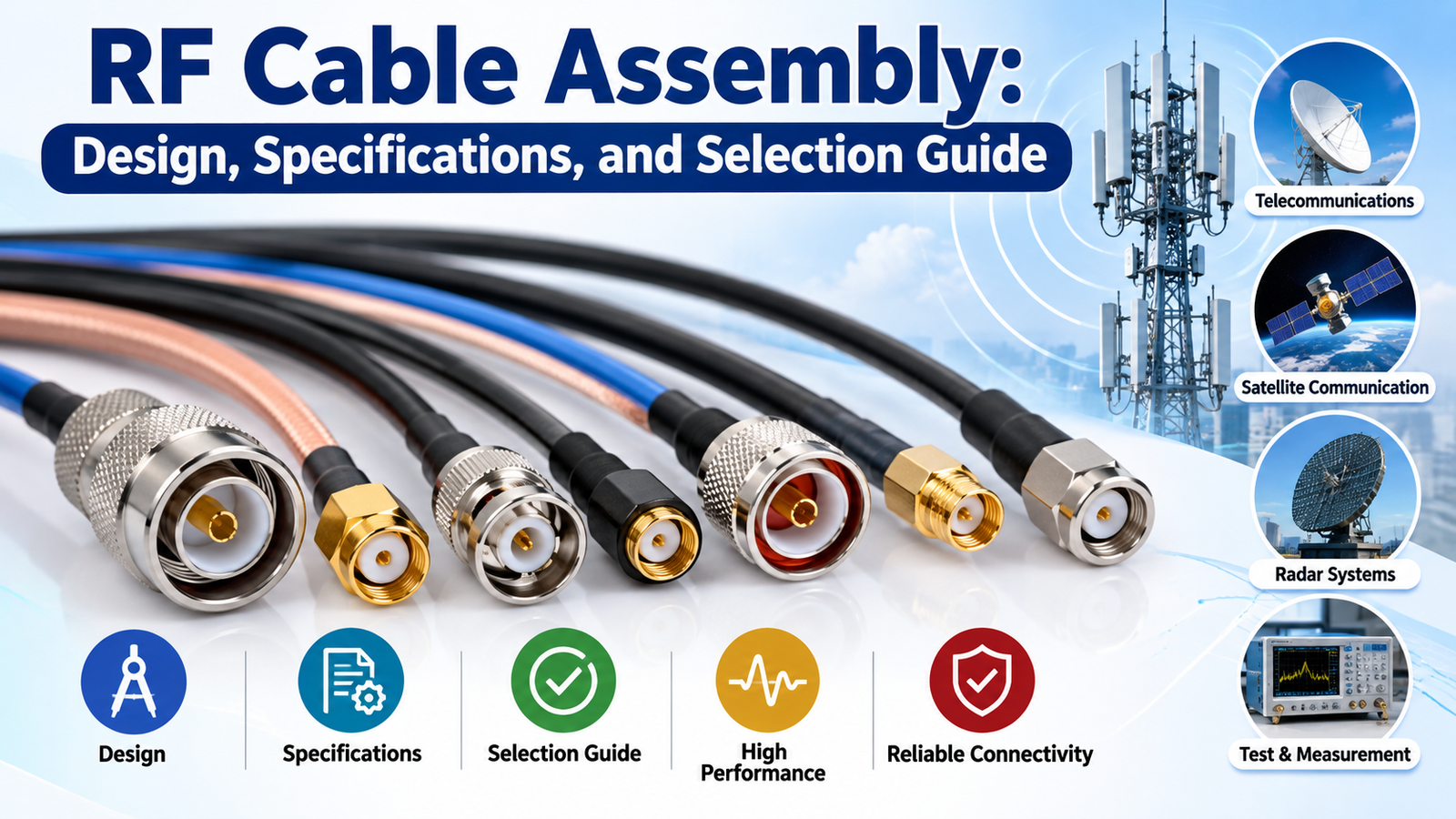
An RF Cable Assembly is a specialized cable solution designed to transmit radio frequency signals between electronic components, antennas, communication equipment, and testing instruments. These assemblies play an essential role in telecommunications, wireless communication, aerospace, defense, radar systems, medical electronics, and industrial testing applications. They typically consist of a coaxial cable, connectors, and, when required, protective components that help maintain signal integrity and reliable electrical performance.
Selecting the right RF Cable Assembly is important for achieving consistent signal transmission, minimizing interference, and supporting the operating requirements of modern electronic systems. Factors such as frequency range, impedance, insertion loss, shielding effectiveness, connector compatibility, and environmental conditions influence the design and performance of an assembly.
This guide explains RF Cable Assembly design, key specifications, available configurations, and practical considerations for selecting a suitable solution for different applications.
What Is an RF Cable Assembly?
An RF Cable Assembly is an integrated cable-and-connector solution engineered to carry high-frequency electrical signals from one point to another. Unlike ordinary electrical cables, RF cable assemblies are designed to control signal reflections, reduce electromagnetic interference, and maintain predictable electrical characteristics across a specified frequency range.
A typical assembly uses a coaxial cable structure consisting of a central conductor, dielectric insulation, an outer conductive shield, and an external protective jacket. Connectors are attached to the cable ends to provide secure electrical connections with antennas, transmitters, receivers, test equipment, and other RF components.
RF Cable Assemblies are available in standard and custom configurations. They can differ in cable length, connector type, impedance, flexibility, shielding, frequency capability, and environmental resistance. The appropriate design depends on the intended application and the electrical and mechanical requirements of the system.
Key Components of an RF Cable Assembly
Understanding the primary components helps engineers evaluate assembly construction and performance.
1. Coaxial Cable
The coaxial cable forms the main transmission path for RF signals. Its construction influences attenuation, flexibility, power handling, shielding, and operating frequency. Cable selection depends on the required electrical performance, installation space, routing conditions, and expected service life.
2. Inner Conductor
The inner conductor carries the RF signal. It may be made from copper, silver-plated copper, or other suitable conductive materials. Its dimensions, material, and surface characteristics influence resistance and high-frequency performance.
3. Dielectric Insulation
The dielectric separates the inner conductor from the outer conductor and helps establish the cable’s characteristic impedance. Common dielectric materials include polyethylene, PTFE, and other engineered polymers. Material selection affects signal velocity, dielectric loss, temperature resistance, and flexibility.
4. Outer Conductor and Shielding
The outer conductor provides the signal return path and helps protect the transmitted signal from external electromagnetic interference. Depending on the design, it may use braided wire, foil, solid metal tubing, or a combination of shielding layers.
5. RF Connectors
Connectors provide the interface between the cable and connected equipment. Common types include SMA, SMB, SMC, BNC, TNC, N-Type, 2.92 mm, 2.4 mm, SMP, and SMPM connectors. Each type has specific mating, frequency, dimensional, and performance characteristics.
6. Protective Jacket and Strain Relief
The outer jacket protects the cable from abrasion, moisture, chemicals, and environmental exposure. Strain relief helps reduce mechanical stress near the connector termination, supporting durability during installation and use.
RF Cable Assembly Design Considerations
Designing an RF Cable Assembly requires balancing electrical performance, mechanical requirements, environmental conditions, and installation constraints.
Electrical Design
Electrical design begins with the required operating frequency, characteristic impedance, and signal performance. The cable and connectors must work together as a compatible transmission path. Impedance discontinuities, poor terminations, or unsuitable connector interfaces can increase reflections and degrade system performance.
Engineers should also evaluate attenuation, voltage standing wave ratio (VSWR), return loss, shielding effectiveness, and power requirements. These parameters should be assessed across the intended frequency range rather than at a single frequency whenever the application requires broadband performance.
Mechanical Design
Mechanical design determines the cable’s dimensions, flexibility, bend radius, connector orientation, and routing requirements. Flexible assemblies are useful where equipment moves or installation space is restricted. Semi-rigid and low-loss cable options may be suitable for applications that prioritize dimensional stability and predictable electrical performance.
The cable should not be bent beyond its specified minimum bend radius. Excessive bending, twisting, pulling, or repeated movement can damage the cable structure and affect signal characteristics.
Connector Termination Design
Connector termination is a critical part of RF assembly manufacturing. Incorrect stripping dimensions, poor soldering, improper crimping, or damaged interfaces can introduce impedance discontinuities and unreliable connections.
Manufacturing processes should follow the cable and connector manufacturer’s specifications. Appropriate assembly methods, inspection procedures, and electrical testing help ensure that the completed product meets the required performance criteria.
Environmental Design
Environmental conditions influence material and construction choices. Outdoor installations may require protection against moisture, ultraviolet exposure, and temperature variation. Aerospace, defense, and industrial applications may require additional resistance to vibration, shock, chemicals, or extreme temperatures.
For demanding environments, the complete assembly should be evaluated against the applicable operating conditions and qualification requirements.
Important RF Cable Assembly Specifications
Understanding the main specifications makes it easier to compare cable assemblies and identify a suitable configuration.
1. Frequency Range
Frequency range defines the frequencies over which an assembly is intended to operate within specified performance limits. Applications such as wireless communication, satellite systems, radar, and RF testing may require different frequency capabilities.
The usable frequency range depends on the cable, connectors, termination quality, and assembly design. Always verify the performance of the complete assembly at the intended operating frequencies.
2. Characteristic Impedance
Characteristic impedance is a fundamental transmission-line parameter, expressed in ohms. Common RF cable impedance values include 50 ohms and 75 ohms.
A 50-ohm RF Cable Assembly is widely used in radio communication, wireless infrastructure, laboratory testing, and many RF systems. A 75-ohm assembly is commonly used in video distribution, broadcast, and certain telecommunications applications.
The cable impedance, connector interfaces, and equipment ports should be matched to reduce signal reflections.
3. Insertion Loss
Insertion loss measures the reduction in signal power as a signal passes through the assembly. It is usually expressed in decibels (dB). Lower insertion loss can be important in systems where signal strength, receiver sensitivity, or transmission distance is a concern.
Insertion loss generally increases with cable length and frequency. Connector interfaces and termination quality also contribute to overall loss.
4. Return Loss and VSWR
Return loss indicates how much signal is reflected because of impedance mismatches. A higher return-loss value generally indicates better matching. VSWR describes the relationship between maximum and minimum voltage levels in a standing wave pattern; a value closer to 1:1 indicates a better match.
These parameters are especially important in precision RF systems, antenna connections, and high-frequency test setups.
5. Shielding Effectiveness
Shielding effectiveness describes the assembly’s ability to limit electromagnetic interference entering or escaping the cable. Shielding requirements depend on signal sensitivity, surrounding electrical noise, and applicable system standards.
Multiple shielding layers may improve interference protection, although performance depends on the entire cable construction and connector termination.
6. Cable Length and Bend Radius
Cable length influences insertion loss, routing, and installation convenience. The selected length should accommodate the connection path without unnecessary excess cable.
Minimum bend radius is equally important because tight bends can affect impedance, attenuation, and mechanical integrity. Flexible assemblies should be selected according to the actual movement and installation requirements.
7. Power Handling and Environmental Ratings
Power-handling capability depends on frequency, cable dimensions, materials, temperature, cooling conditions, and connector ratings. The manufacturer’s specifications should be checked for the actual operating conditions.
Temperature range, moisture resistance, vibration tolerance, and jacket material should also be reviewed when the assembly will operate in challenging environments.
Common Types of RF Cable Assemblies
Different assembly types serve different performance and installation requirements.
Flexible RF Cable Assemblies
Flexible assemblies use bendable coaxial cables and are suitable for general RF interconnections, telecommunications equipment, laboratory instruments, and installations requiring easier routing.
Low-Loss RF Cable Assemblies
Low-loss assemblies are designed to reduce signal attenuation, making them useful for antenna feeders, wireless infrastructure, and longer RF signal paths. Their actual performance depends on cable construction, frequency, and length.
Semi-Rigid RF Cable Assemblies
Semi-rigid assemblies use a metal outer conductor that maintains its shape after forming. They are often used in compact electronic equipment and applications requiring stable electrical characteristics and controlled cable routing.
High-Frequency RF Cable Assemblies
High-frequency assemblies use compatible cables and precision connectors to support demanding microwave and millimeter-wave applications. Connector interface accuracy, assembly workmanship, and test frequency are especially important.
Custom RF Cable Assemblies
Custom assemblies are manufactured to meet specific requirements involving cable length, connector combinations, phase stability, flexibility, environmental protection, or specialized electrical performance.
How to Select the Right RF Cable Assembly
Choosing an appropriate RF Cable Assembly involves evaluating the complete system rather than focusing on one specification.
Step 1: Define the operating frequency. Determine the minimum and maximum frequencies the assembly must support. Select a cable and connector combination with suitable verified performance across this range.
Step 2: Confirm the required impedance. Check the impedance of the equipment, antenna, and other connected components. Ensure the assembly provides compatible interfaces.
Step 3: Evaluate signal loss. Establish the acceptable insertion-loss budget. Consider cable length, frequency, connector count, and the sensitivity of the receiving equipment.
Step 4: Select compatible connectors. Identify the required connector series, gender, interface, and mounting configuration. Confirm that mating components are mechanically and electrically compatible.
Step 5: Assess installation requirements. Consider available space, cable flexibility, minimum bend radius, movement, and connector orientation. These factors influence the assembly’s long-term reliability.
Step 6: Review environmental conditions. Identify exposure to moisture, temperature extremes, vibration, chemicals, or outdoor conditions. Choose suitable materials and protective features.
Step 7: Verify testing and documentation. Request applicable test data for insertion loss, return loss or VSWR, continuity, and other required parameters. For demanding applications, confirm whether phase matching, environmental qualification, or additional acceptance testing is necessary.
Applications of RF Cable Assemblies
RF Cable Assemblies support a broad range of electronic and communication systems.
- Telecommunications: Connect antennas, radios, base stations, and wireless communication equipment.
- Aerospace and Defense: Support radar, navigation, communication, and specialized electronic systems.
- Test and Measurement: Connect network analyzers, spectrum analyzers, signal generators, and RF test fixtures.
- Satellite Communication: Carry RF signals in satellite terminals, ground stations, and related communication equipment.
- Medical Electronics: Support RF connections in compatible medical devices and specialized diagnostic equipment.
- Industrial Electronics: Provide signal connections in automation, monitoring, sensing, and wireless industrial systems.
Each application has different electrical, mechanical, and regulatory requirements, so the assembly should be selected according to the intended system design.
RF Cable Assembly Quality and Testing
Quality assurance helps verify that an RF Cable Assembly meets its specified requirements. Testing may include continuity checks, connector inspection, insertion-loss measurement, return-loss testing, and VSWR measurement. Depending on the application, phase stability, shielding performance, power handling, and environmental tests may also be required.
Visual inspection can identify damaged jackets, incorrect connector orientation, poor workmanship, or other manufacturing defects. Electrical testing provides additional evidence that the assembly performs within its specified limits.
When ordering custom assemblies, customers should communicate the required frequency range, impedance, cable length, connector part numbers, environmental conditions, and acceptance criteria. Clear specifications help manufacturers produce assemblies that integrate correctly into the intended equipment.
Conclusion
RF Cable Assembly design, specifications, and selection are essential considerations in developing reliable high-frequency communication and electronic systems. The right assembly combines a suitable coaxial cable, compatible connectors, appropriate shielding, and verified electrical performance.
By evaluating frequency range, impedance, insertion loss, return loss, VSWR, cable flexibility, environmental conditions, and testing requirements, engineers can select an assembly that meets their application needs. Careful design and proper installation help maintain signal integrity, reduce connection-related problems, and support consistent system operation.
Whether the requirement involves telecommunications infrastructure, precision test equipment, aerospace electronics, or a custom RF application, choosing an RF Cable Assembly based on clearly defined specifications helps improve compatibility, reliability, and long-term performance.
Frequently Asked Questions (FAQs)
1. What is an RF Cable Assembly?
An RF Cable Assembly is a cable-and-connector solution designed to transmit radio frequency signals between electronic devices, antennas, communication systems, and test equipment.
2. What are the common impedance values for RF Cable Assemblies?
The most common impedance values are 50 ohms and 75 ohms. The appropriate value depends on the connected equipment and application requirements.
3. Which connectors are used in RF Cable Assemblies?
Common connectors include SMA, SMB, SMC, BNC, TNC, N-Type, 2.92 mm, 2.4 mm, SMP, and SMPM. The choice depends on frequency, interface compatibility, and mechanical requirements.
4. What specifications should be checked before selecting an RF Cable Assembly?
Important specifications include frequency range, characteristic impedance, insertion loss, return loss, VSWR, shielding effectiveness, cable length, bend radius, power handling, and environmental ratings.
5. What is the difference between flexible and semi-rigid RF Cable Assemblies?
Flexible assemblies are easier to route and bend, while semi-rigid assemblies use a formable metal outer conductor that maintains its shape and can provide stable electrical characteristics in suitable applications.
6. Why is insertion loss important in RF Cable Assemblies?
Insertion loss indicates how much signal power is lost while passing through the assembly. Lower loss can help preserve signal strength, particularly in longer cable runs and sensitive RF systems.
7. Can RF Cable Assemblies be customized?
Yes. Custom assemblies can be produced with specific cable lengths, connector combinations, impedance requirements, shielding configurations, and environmental characteristics, subject to the manufacturer’s capabilities.
8. How are RF Cable Assemblies tested?
Depending on the requirements, testing may include continuity, insertion loss, return loss, VSWR, connector inspection, and specialized environmental or phase-stability testing.
9. How does cable length affect RF Cable Assembly performance?
Longer cables generally introduce greater insertion loss. Cable length should therefore be selected to meet installation requirements while maintaining the system’s signal-loss budget.
10. Which industries use RF Cable Assemblies?
RF Cable Assemblies are used in telecommunications, aerospace, defense, satellite communication, medical electronics, industrial systems, and RF test and measurement applications.










