
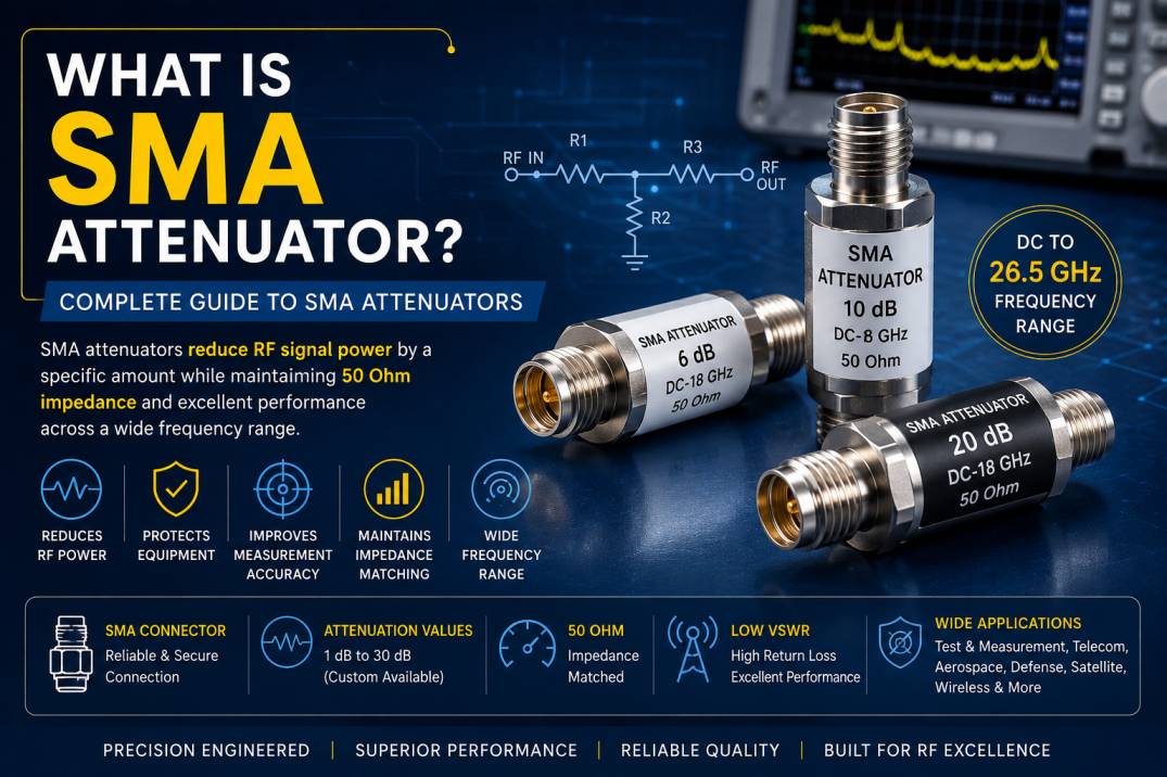
An SMA attenuator is a passive RF component used to reduce the power level of a radio frequency signal by a specific amount while maintaining a controlled impedance and minimizing signal reflections. SMA attenuators are widely used in RF, microwave, wireless communication, telecommunications, aerospace, defense, satellite communication, test and measurement, radar, and electronic systems.
The term SMA refers to SubMiniature version A, a compact coaxial RF connector interface commonly used for high-frequency applications. An SMA attenuator combines this connector interface with an internal resistive or engineered attenuation network to provide a specified level of signal reduction.
Common attenuation values include 1 dB, 2 dB, 3 dB, 5 dB, 6 dB, 10 dB, 15 dB, 20 dB, and 30 dB, although custom attenuation values are also available for specialized RF systems.
SMA attenuators are available in male-to-male, male-to-female, and female-to-female configurations, as well as fixed, variable, programmable, high-power, low-PIM, DC-pass, DC-blocking, and precision microwave versions.
What Is an SMA Attenuator?
An SMA attenuator is a passive two-port RF device with SMA connectors that reduces the amplitude or power of an RF signal by a predetermined amount.
For example, if a signal entering an SMA attenuator has a power level of 0 dBm and the attenuator provides 10 dB attenuation, the theoretical output power is approximately -10 dBm, assuming negligible additional losses.
The primary purpose of an SMA attenuator is not to amplify, filter, or switch the signal. Instead, it provides controlled signal reduction to protect equipment, improve impedance matching, establish appropriate operating levels, and support accurate RF measurements.
What Does SMA Mean?
SMA stands for SubMiniature version A.
The SMA connector is a compact coaxial RF connector commonly used in high-frequency systems. Standard SMA interfaces are typically designed around a 50-ohm characteristic impedance, making them suitable for many RF and microwave applications.
SMA connectors are valued for:
- Compact size
- Reliable mechanical connection
- Good RF performance
- Wide frequency availability
- Low VSWR options
- High repeatability
- Easy integration into RF equipment
The performance of an SMA attenuator depends on the connector design, internal attenuation network, materials, manufacturing precision, and specified operating frequency.
How Does an SMA Attenuator Work?
An SMA attenuator works by introducing a controlled amount of resistance or other attenuation structure into the RF signal path.
The attenuation network absorbs part of the RF power and converts it primarily into heat. The remaining RF energy continues through the output port at a lower power level.
A properly designed attenuator maintains the desired impedance while reducing signal amplitude.
Basic Signal Flow
RF Source → SMA Input → Attenuation Network → SMA Output → RF Load
The attenuation value determines how much the signal power is reduced.
For example:
- 3 dB attenuator reduces power to approximately 50%
- 6 dB attenuator reduces power to approximately 25%
- 10 dB attenuator reduces power to approximately 10%
- 20 dB attenuator reduces power to approximately 1%
Understanding RF Attenuation in dB
Attenuation is normally specified in decibels (dB).
The power attenuation relationship is:
Attenuation (dB) = 10 log10(Pin / Pout)
Where:
- Pin = input power
- Pout = output power
The voltage relationship depends on the impedance of the RF system.
For a 50-ohm system, commonly used in SMA RF applications, the relationship between voltage ratio and attenuation is:
Attenuation (dB) = 20 log10(Vin / Vout)
Common SMA Attenuator Values
| Attenuation | Approximate Output Power |
|---|---|
| 1 dB | 79.4% |
| 2 dB | 63.1% |
| 3 dB | 50.1% |
| 5 dB | 31.6% |
| 6 dB | 25.1% |
| 10 dB | 10% |
| 15 dB | 3.16% |
| 20 dB | 1% |
| 30 dB | 0.1% |
These values describe ideal power ratios and do not account for additional insertion losses or frequency-dependent performance.
Why Are SMA Attenuators Used?
RF equipment often requires a specific signal level to operate correctly. Excessive RF power can overload an amplifier, receiver, detector, spectrum analyzer, signal generator input, or measurement instrument.
An SMA attenuator can be inserted into the signal path to reduce the power to a suitable level.
Common reasons for using an SMA attenuator include:
- Reducing excessive RF power
- Protecting sensitive equipment
- Improving impedance matching
- Reducing signal amplitude
- Controlling RF test levels
- Reducing reflections
- Improving measurement accuracy
- Creating a known signal level
- Isolating RF circuits
- Matching different RF system requirements
Types of SMA Attenuators
SMA attenuators are available in several configurations depending on application and performance requirements.
1. Fixed SMA Attenuator
A fixed SMA attenuator provides a constant attenuation value.
Common values include:
- 1 dB
- 2 dB
- 3 dB
- 5 dB
- 6 dB
- 10 dB
- 15 dB
- 20 dB
- 30 dB
Fixed attenuators are the most common type because they provide predictable and stable attenuation.
Applications
- RF test equipment
- Signal generators
- Spectrum analyzers
- Network analyzers
- Wireless systems
- RF development laboratories
- Communication equipment
2. Variable SMA Attenuator
A variable SMA attenuator allows the attenuation level to be adjusted across a defined range.
Instead of providing one fixed attenuation value, the user can change the attenuation depending on the test or system requirement.
Applications
- RF laboratories
- Calibration systems
- Signal testing
- Communication system development
- Receiver sensitivity testing
- RF characterization
3. Step SMA Attenuator
A step attenuator provides predefined attenuation settings.
For example, a step attenuator may offer selectable values such as:
0 dB, 2 dB, 4 dB, 6 dB, 8 dB, 10 dB, 20 dB, and 30 dB.
Multiple attenuation stages can be combined to create a required signal level.
4. High-Power SMA Attenuator
High-power SMA attenuators are designed to handle greater RF power than standard low-power attenuators.
The maximum power rating depends on:
- Frequency
- Attenuation value
- Internal construction
- Heat dissipation
- Connector design
- Duty cycle
- Ambient temperature
High-power SMA attenuators are used in transmitters, RF amplifiers, test systems, and communication equipment.
5. Precision SMA Attenuator
Precision SMA attenuators are manufactured for applications requiring highly controlled RF characteristics.
They are typically selected for:
- Low VSWR
- High return loss
- Accurate attenuation
- Low frequency variation
- High repeatability
- Precision measurement
These attenuators are particularly valuable in RF calibration and test-and-measurement systems.
6. DC-Pass SMA Attenuator
A DC-pass SMA attenuator allows a DC component to pass through the RF path while attenuating the RF signal.
This configuration is useful in systems where bias voltage is required along with RF transmission.
Applications can include:
- Active antennas
- RF amplifiers
- Bias circuits
- Microwave modules
- Semiconductor test systems
7. DC-Block SMA Attenuator
A DC-blocking attenuator prevents DC voltage from passing between the two RF ports while providing RF attenuation.
This is useful when the RF signal must pass but DC isolation is required.
8. SMA Male Attenuator
An SMA male attenuator uses a male SMA connector on the specified port.
It is selected according to the mating connector on the RF equipment or cable assembly.
9. SMA Female Attenuator
An SMA female attenuator uses a female SMA interface.
Female SMA attenuators are commonly used where the RF system or cable terminates in an SMA male connector.
10. SMA Male-to-Female Attenuator
A male-to-female SMA attenuator combines attenuation with connector gender conversion.
This can eliminate the need for an additional adapter in certain RF configurations.
SMA Attenuator Specifications
When selecting an SMA attenuator, several technical parameters should be evaluated.
| Parameter | Typical Consideration |
|---|---|
| Connector | SMA |
| Impedance | 50 Ohm |
| Attenuation | 1–30 dB or custom |
| Frequency | Application dependent |
| Power Rating | Application dependent |
| VSWR | Low VSWR preferred |
| Return Loss | High return loss preferred |
| Connector Gender | Male, Female or Male-to-Female |
| Construction | Coaxial / resistive / precision |
| Operating Temperature | Application dependent |
| Application | RF, microwave, test, telecom, defense |
The exact specifications must always be selected according to the particular SMA attenuator model.
Frequency Range of SMA Attenuators
SMA attenuators are available across a broad range of frequencies.
Depending on the design, SMA attenuators may support:
- DC to several GHz
- DC to 6 GHz
- DC to 12 GHz
- DC to 18 GHz
- DC to 26.5 GHz
- Higher microwave frequencies with specialized designs
As frequency increases, connector geometry, mechanical tolerances, dielectric materials, internal construction, and manufacturing accuracy become increasingly important.
SMA Attenuator Power Rating
Power handling is one of the most important specifications when selecting an RF attenuator.
A common mistake is to assume that a 10 dB attenuator can handle the same power at every frequency.
In reality, maximum power can vary according to:
- Frequency
- Attenuation value
- Ambient temperature
- Duty cycle
- Pulse characteristics
- Cooling conditions
- Mechanical construction
For pulsed RF applications, peak power and average power should both be evaluated.
SMA Attenuator vs RF Termination
An SMA attenuator and an SMA termination are both passive RF components, but they perform different functions.
An SMA attenuator reduces the signal level while allowing the RF signal to continue through to another component.
An SMA termination is generally used to terminate an RF port and absorb incident RF power to minimize reflections.
Comparison
| Feature | SMA Attenuator | SMA Termination |
|---|---|---|
| Main Function | Reduce signal | Terminate signal |
| Ports | Two-port | Typically one-port |
| Signal Output | Yes | No |
| Attenuation | Specified dB value | Usually not the primary function |
| Common Use | Signal control | Port termination |
| Measurement Use | Yes | Yes |
SMA Attenuator vs SMA Adapter
An SMA adapter primarily changes connector interface, gender, or series configuration.
An SMA attenuator reduces RF signal power.
An adapter may provide almost no intentional attenuation, whereas an attenuator is specifically designed to provide a known attenuation value.
SMA Attenuator vs RF Cable
An RF cable transfers RF energy from one point to another.
An SMA attenuator intentionally reduces the signal level.
A cable may introduce unwanted insertion loss, while an attenuator is designed to provide a controlled and specified attenuation.
Importance of VSWR in SMA Attenuators
VSWR is an important specification for RF attenuators because impedance mismatch can cause signal reflections.
An ideal 50-ohm attenuator presents a 50-ohm impedance to the connected RF system.
Low VSWR helps reduce reflections and supports better signal integrity.
High-quality SMA attenuators are designed to maintain low VSWR across their specified frequency range.
Return Loss of SMA Attenuators
Return loss measures the amount of RF power reflected back toward the source.
Higher return loss generally indicates better impedance matching.
For precision RF applications, both attenuation accuracy and return loss are important.
A good attenuator should provide:
- Stable attenuation
- Low VSWR
- High return loss
- Low frequency variation
- High repeatability
Insertion Loss vs Attenuation
Attenuation and insertion loss are related but should not be treated as exactly the same specification.
The nominal attenuation of an SMA attenuator is the intended signal reduction, such as 10 dB.
Insertion loss describes the reduction in transmitted signal caused by inserting a component into the RF path.
For an attenuator, the specified attenuation is intentionally large, while additional deviations from the nominal value are important when precision is required.
SMA Attenuator Applications
SMA attenuators are used across many RF and microwave industries.
RF Test and Measurement
They are widely used with:
- Spectrum analyzers
- Signal generators
- Vector network analyzers
- Power meters
- RF receivers
- RF sources
They allow engineers to establish controlled signal levels during testing.
Telecommunications
SMA attenuators can be used in RF modules, wireless communication equipment, network infrastructure, and signal distribution systems.
Aerospace
Aerospace RF systems often require compact and reliable attenuators for communication, navigation, radar, and test systems.
Defense
RF attenuators are used in communication systems, electronic test equipment, radar systems, and RF subsystem development.
Satellite Communication
SMA attenuators can be used in satellite RF equipment, ground stations, transceiver modules, and test systems.
Wireless Communication
They can be used in cellular, WLAN, IoT, private wireless, and other RF communication equipment.
Laboratory Testing
Engineers use SMA attenuators to control signal levels during circuit characterization, receiver testing, amplifier testing, and calibration.
SMA Attenuators in RF Testing
RF test equipment often operates within specific input power limits.
For example, a signal generator may produce a stronger signal than a receiver input can safely accept. An SMA attenuator can be inserted between the source and receiver to reduce the signal.
This makes attenuators valuable for:
- Receiver sensitivity testing
- Dynamic range testing
- Amplifier testing
- VNA measurements
- Signal level calibration
- RF component characterization
SMA Attenuators in Amplifier Testing
When testing an RF amplifier, an attenuator can help control the signal entering or leaving the amplifier.
It can also provide a controlled impedance environment and help protect sensitive measurement equipment.
For high-power amplifier testing, the attenuator must be selected with an appropriate power rating and thermal design.
SMA Attenuators for Signal Level Control
Signal level management is one of the simplest and most important applications of an attenuator.
A system may require a signal to be reduced from a high level to a lower level before entering:
- Receiver
- Detector
- Mixer
- ADC
- Spectrum analyzer
- Power sensor
- RF amplifier
An appropriately selected SMA attenuator provides predictable signal reduction.
Benefits of SMA Attenuators
Controlled Signal Reduction
SMA attenuators provide a known amount of attenuation.
Compact Size
SMA connectors and coaxial attenuator structures are suitable for space-constrained RF systems.
Easy Installation
Many SMA attenuators can be connected directly between an RF cable and equipment port.
Impedance Matching
Well-designed attenuators provide a controlled 50-ohm interface.
Equipment Protection
Attenuators can reduce excessive RF power before it reaches sensitive equipment.
Improved Measurement Control
They help engineers establish repeatable signal levels during RF testing.
Wide Frequency Availability
SMA attenuators are available for many RF and microwave frequency ranges.
How to Select the Right SMA Attenuator
Selecting an SMA attenuator requires more than choosing an attenuation value.
1. Determine Required Attenuation
Calculate how much signal reduction is required.
For example, if a signal must be reduced by approximately 10 dB, select a 10 dB attenuator.
2. Check Frequency Range
The attenuator must support the entire operating frequency range of the RF system.
3. Check Power Rating
Ensure that the attenuator can safely handle the expected average and peak power.
4. Check Connector Gender
Verify whether the application requires SMA male, SMA female, or a male-to-female configuration.
5. Check VSWR
For precision RF applications, select a low-VSWR attenuator.
6. Check Attenuation Accuracy
Precision applications may require tight attenuation tolerance.
7. Check Temperature Rating
For outdoor, aerospace, industrial, or high-power applications, operating temperature should be considered.
8. Consider DC Requirements
Determine whether DC needs to pass through or be blocked.
9. Consider Mechanical Requirements
Check connector orientation, body size, mounting requirements, and available space.
Common SMA Attenuator Selection Mistakes
Selecting an Attenuator Without Checking Frequency
An attenuator’s performance can change with frequency. Always verify the specified operating range.
Ignoring Power Rating
Exceeding the attenuator’s power rating can cause overheating and permanent damage.
Choosing Gain Instead of Radiation or Signal Requirements
For antenna systems and RF networks, the entire signal chain should be evaluated rather than focusing on one specification.
Ignoring Connector Compatibility
SMA, RP-SMA, and other connector interfaces are not automatically interchangeable.
Using a Standard Attenuator in a Precision Application
Measurement and calibration applications may require precision attenuators with tighter specifications.
SMA Attenuator Quality Factors
A high-quality SMA attenuator should be evaluated based on:
- Attenuation accuracy
- Frequency response
- VSWR
- Return loss
- Power handling
- Connector quality
- Mechanical durability
- Temperature stability
- Repeatability
- Manufacturing consistency
For demanding applications, precision machining and controlled RF manufacturing processes are particularly important.
SMA Attenuators for High-Frequency Applications
As RF systems move toward higher frequencies, the mechanical and electrical design of the attenuator becomes increasingly critical.
At higher frequencies, small variations in:
- Connector dimensions
- Contact geometry
- Dielectric material
- Internal conductor dimensions
- Surface finish
- Assembly tolerances
can affect RF performance.
High-frequency SMA attenuators therefore require precision manufacturing and careful RF characterization.
SMA Attenuators for 5G and Wireless Systems
Modern wireless infrastructure uses a broad range of RF components for signal distribution, testing, filtering, amplification, and measurement.
SMA attenuators can be useful in:
- 5G RF testing
- Small-cell development
- Wireless modules
- RF front-end testing
- Base-station testing
- Antenna testing
- Device certification
They provide controlled signal levels during development and verification.
SMA Attenuators in RF Cable Assemblies
An SMA attenuator can be connected directly to an RF cable assembly when controlled attenuation is required.
For example:
RF Source → SMA Cable Assembly → SMA Attenuator → RF Device
This configuration allows engineers to introduce a known amount of signal reduction without redesigning the complete RF system.
SMA Attenuator Installation Guidelines
Proper installation is important for maintaining RF performance.
Keep Connections Clean
Dust, contamination, and damaged connector surfaces can degrade RF performance.
Avoid Excessive Mechanical Stress
Do not use the attenuator body as a lever while tightening the connector.
Use Appropriate Torque
Where specified by the manufacturer, use the recommended SMA connector torque.
Avoid Sharp Cable Bends
Excessive bending near the connector can damage the cable and affect RF performance.
Verify Power Before Connection
Ensure the expected RF power is within the attenuator’s rated operating range.
Testing SMA Attenuators
SMA attenuators can be tested using RF test equipment such as a vector network analyzer.
Common measurements include:
- Insertion loss
- Return loss
- VSWR
- Attenuation accuracy
- Frequency response
- Phase response
For high-precision applications, calibration should be performed using appropriate standards and procedures.
Maintenance of SMA Attenuators
SMA attenuators generally require minimal maintenance because they are passive components.
However, users should:
- Keep connectors clean
- Inspect mating surfaces
- Avoid over-tightening
- Protect unused connectors
- Store components in clean environments
- Avoid exceeding power specifications
- Prevent mechanical shock
SMA Attenuator Market and Technology Trends
RF systems are moving toward higher frequencies, smaller form factors, greater power density, and tighter signal integrity requirements.
Important trends include:
- Higher-frequency SMA attenuators
- Compact precision attenuators
- High-power RF attenuators
- Low-VSWR designs
- Improved thermal management
- Broadband attenuation
- Precision calibration components
- Custom RF attenuation solutions
- Miniaturized microwave components
The increasing adoption of 5G, satellite communications, radar, aerospace electronics, advanced wireless systems, and high-frequency test equipment continues to create demand for reliable RF attenuation components.
Why Choose a Quality SMA Attenuator Manufacturer?
A reliable manufacturer should be able to provide consistent electrical and mechanical performance.
Important supplier capabilities include:
- Precision RF manufacturing
- Controlled impedance design
- High-quality SMA connectors
- RF performance testing
- Attenuation verification
- Power testing
- VSWR measurement
- Frequency characterization
- Custom design capability
- Quality control documentation
For critical applications, customers should request complete technical specifications and test data before selecting a component.
Conclusion
An SMA attenuator is an essential passive RF component used to reduce signal power by a controlled amount while maintaining a suitable RF interface. Its compact SMA connector configuration makes it highly useful in RF and microwave systems where space, signal integrity, and reliable connections are important.
Fixed, variable, step, high-power, precision, DC-pass, and DC-blocking SMA attenuators are available for different applications. Selecting the correct model requires careful consideration of attenuation value, frequency range, power rating, VSWR, return loss, connector configuration, operating temperature, and mechanical requirements.
SMA attenuators are widely used in telecommunications, aerospace, defense, satellite communication, wireless systems, RF laboratories, test and measurement equipment, and high-frequency electronics.
For reliable RF performance, an SMA attenuator should always be selected according to the complete electrical and mechanical requirements of the application rather than attenuation value alone.
Frequently Asked Questions About SMA Attenuators
1. What is an SMA attenuator?
An SMA attenuator is a passive RF component that reduces the power of an RF signal by a specified amount while providing an SMA connector interface.
2. What does SMA stand for?
SMA stands for SubMiniature version A. It is a compact coaxial RF connector commonly used in RF and microwave systems.
3. What is the impedance of an SMA attenuator?
Most SMA RF systems use a 50-ohm impedance. However, the exact impedance should always be verified from the component datasheet.
4. What are common SMA attenuator values?
Common attenuation values include 1 dB, 2 dB, 3 dB, 5 dB, 6 dB, 10 dB, 15 dB, 20 dB, and 30 dB.
5. What is a 10 dB SMA attenuator?
A 10 dB SMA attenuator reduces RF power to approximately one-tenth of the input power under ideal conditions.
6. What is the difference between an SMA attenuator and an SMA termination?
An SMA attenuator reduces an RF signal while passing it to another port. An SMA termination is used to terminate an RF port and absorb incident RF power.
7. Can an SMA attenuator be used for high-power RF signals?
Yes, high-power SMA attenuators are available. However, the attenuator must have an appropriate power rating for the frequency, average power, peak power, and operating conditions.
8. What is VSWR in an SMA attenuator?
VSWR indicates the degree of impedance matching between the attenuator and the RF system. Lower VSWR generally indicates better matching.
9. Can an SMA attenuator be used with a VNA?
Yes. SMA attenuators are commonly used with vector network analyzers for controlled signal levels, measurement setups, calibration configurations, and RF component testing.
10. What is a fixed SMA attenuator?
A fixed SMA attenuator provides a predetermined attenuation value that cannot be adjusted during normal operation.
11. What is a variable SMA attenuator?
A variable SMA attenuator allows the user to adjust attenuation across a specified range.
12. What is a high-power SMA attenuator?
A high-power SMA attenuator is designed to dissipate greater RF power than a standard attenuator while maintaining specified RF performance.
13. Does an SMA attenuator reduce voltage and power?
Yes. Attenuation reduces both voltage and power according to the impedance and attenuation value of the RF system.
14. How do I choose an SMA attenuator?
Consider the required attenuation, frequency range, power rating, connector gender, impedance, VSWR, attenuation accuracy, operating temperature, and whether DC should pass or be blocked.
15. Are SMA attenuators used in 5G systems?
Yes. SMA attenuators are widely useful in RF testing, development, characterization, and measurement of wireless and 5G-related equipment.
16. What is the difference between SMA male and SMA female attenuators?
The difference is the connector interface. SMA male and SMA female configurations are selected according to the mating connectors in the RF system.
17. Can an SMA attenuator improve impedance matching?
A properly designed attenuator can provide a controlled 50-ohm interface and, depending on the application, can help reduce mismatch effects and reflections.
18. Do SMA attenuators have frequency limitations?
Yes. Every SMA attenuator has a specified operating frequency range. RF performance should not be assumed outside the manufacturer’s rated frequency range.
19. Are SMA attenuators bidirectional?
Many passive fixed SMA attenuators are electrically usable in either direction, but the manufacturer should be consulted for the specific component, particularly for specialized or DC-sensitive designs.
20. Why are SMA attenuators important in RF systems?
SMA attenuators provide controlled signal reduction, protect sensitive equipment, support RF testing, manage signal levels, and help engineers build predictable and repeatable RF systems.










