
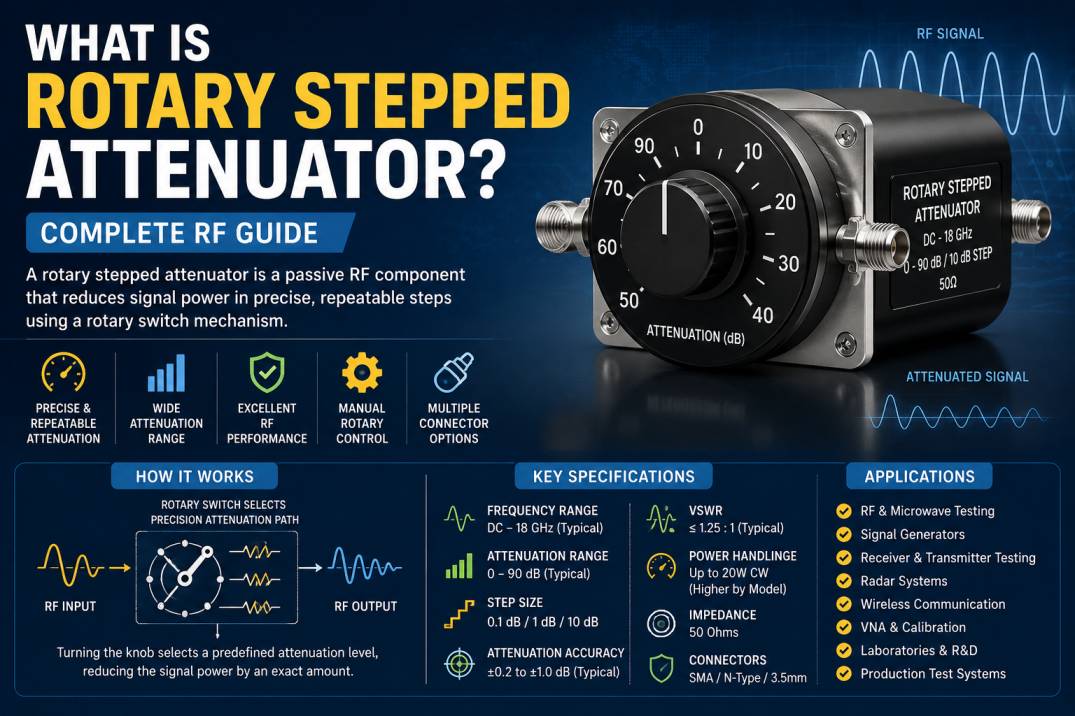
A rotary stepped attenuator is a passive RF and microwave component used to reduce the power level of an RF signal by a precisely defined amount in discrete steps. Unlike a continuously variable attenuator, which provides smooth attenuation adjustment, a rotary stepped attenuator uses a mechanical rotary control with predefined attenuation positions.
Each position of the rotary switch selects a specific attenuation value. Depending on the design, the user may select attenuation levels such as 0 dB, 1 dB, 2 dB, 3 dB, 5 dB, 10 dB, or larger values. Some RF rotary stepped attenuators are designed with 0.1 dB or 1 dB resolution, while others use larger step sizes such as 10 dB.
Rotary stepped attenuators are widely used in RF test and measurement, telecommunications, wireless communication, radar, transmitters, laboratories, calibration systems, and microwave equipment.
The key advantage of a rotary stepped attenuator is repeatable and controlled signal-level adjustment. Instead of manually changing cables or fixed attenuator pads, an operator can simply rotate the control to select the required attenuation.
What Is a Rotary Stepped Attenuator?
A rotary stepped attenuator is a manually adjustable RF attenuator that provides a predetermined set of attenuation levels through a rotary switching mechanism.
An RF attenuator reduces signal power while maintaining the desired impedance and minimizing signal distortion. In RF systems, attenuators are commonly designed around a 50-ohm impedance, although other impedance standards are possible.
The “rotary” part refers to the mechanical control used to select an attenuation state, while “stepped” means that attenuation changes occur in discrete increments rather than continuously.
For example, a rotary stepped attenuator with a 0–90 dB range and 10 dB steps can provide selectable settings such as:
0 dB → 10 dB → 20 dB → 30 dB → 40 dB → 50 dB → 60 dB → 70 dB → 80 dB → 90 dB
The actual available positions depend on the product design.
How Does a Rotary Stepped Attenuator Work?
A rotary stepped attenuator typically contains multiple precision attenuation networks and a switching mechanism.
When the rotary knob is turned, the internal switch changes the RF signal path. Different switch positions introduce different amounts of attenuation into the signal path.
The basic operating process is:
- RF signal enters the attenuator.
- The rotary control is set to a specific position.
- The internal switching network selects an attenuation state.
- The selected attenuation network reduces the RF signal level.
- The attenuated signal exits through the output connector.
RF step attenuators can be constructed from multiple fixed attenuator sections that are selectively inserted into the RF path.
For example, if a system requires a 20 dB reduction, the rotary mechanism selects the appropriate internal attenuation network.
Why Is Attenuation Measured in dB?
Attenuation is normally expressed in decibels (dB).
For power:
Attenuation (dB) = 10 log10(Pin / Pout)
where:
- Pin = Input power
- Pout = Output power
For example, a 10 dB attenuator reduces the output power to one-tenth of the input power.
A 20 dB attenuator reduces the output power to one-hundredth of the input power.
| Attenuation | Output Power Relative to Input |
|---|---|
| 0 dB | 100% |
| 1 dB | About 79.4% |
| 3 dB | About 50% |
| 6 dB | About 25% |
| 10 dB | 10% |
| 20 dB | 1% |
| 30 dB | 0.1% |
| 40 dB | 0.01% |
This logarithmic representation makes dB particularly useful for RF and microwave systems.
Main Components of a Rotary Stepped Attenuator
A typical rotary stepped attenuator consists of several important components.
RF Input Connector
The input connector connects the attenuator to the RF signal source.
Common connector types include:
- SMA
- N-Type
- 3.5 mm
- Other RF connectors depending on frequency and application
RF Output Connector
The output connector connects the attenuated signal to the next device in the RF chain.
Rotary Switching Mechanism
The rotary mechanism allows the user to select the desired attenuation setting.
Precision Attenuation Networks
These internal networks determine the attenuation level at each switch position.
RF Housing
The conductive housing provides mechanical protection and helps maintain RF shielding.
Control Knob
The knob provides manual control of the attenuation setting.
Detents
Detents provide clearly defined mechanical positions so that the operator can select repeatable attenuation values.
Rotary Stepped Attenuator vs Fixed Attenuator
A fixed attenuator provides one predefined attenuation value, while a rotary stepped attenuator provides multiple selectable values.
| Feature | Fixed Attenuator | Rotary Stepped Attenuator |
|---|---|---|
| Attenuation | One value | Multiple values |
| Adjustment | No | Yes |
| Control | None | Rotary |
| Repeatability | High | High |
| Flexibility | Low | High |
| Application | Permanent signal reduction | Adjustable signal control |
For example, a 10 dB fixed attenuator always provides approximately 10 dB attenuation, while a rotary stepped attenuator might allow the operator to select 0, 10, 20, 30 dB, and other values.
Rotary Stepped Attenuator vs Continuously Variable Attenuator
A continuously variable attenuator allows smooth adjustment across its operating range, while a rotary stepped attenuator provides predefined attenuation positions.
| Parameter | Rotary Stepped | Continuously Variable |
|---|---|---|
| Adjustment | Discrete | Continuous |
| Repeatability | Excellent | Depends on design |
| Resolution | Fixed steps | Continuously adjustable |
| Control | Rotary switch | Variable mechanism |
| Setting Recall | Easy | Less precise |
| Typical Use | Test systems | Fine manual adjustment |
Rotary stepped attenuators are particularly useful when repeatable signal-level settings are required.
Types of Rotary Stepped Attenuators
Rotary stepped attenuators can be categorized according to attenuation range, step size, frequency, power handling, connector configuration, and construction.
1. 0.1 dB Step Rotary Attenuator
A 0.1 dB step attenuator provides very fine attenuation adjustment.
It is useful for applications requiring precise RF signal-level control.
Applications
- RF laboratories
- Calibration
- Test and measurement
- VNA measurements
- Signal generator setups
- Receiver testing
2. 1 dB Step Rotary Attenuator
A 1 dB step is one of the most common configurations for general RF applications.
Typical ranges may include:
- 0–10 dB
- 0–20 dB
- 0–50 dB
- 0–70 dB
- 0–90 dB
- 0–100 dB
Actual ranges depend on the product.
3. 10 dB Step Rotary Attenuator
10 dB step attenuators provide larger attenuation increments and are useful when coarse signal-level adjustment is sufficient.
4. High-Attenuation Rotary Stepped Attenuator
Some designs provide very large attenuation ranges, such as 70 dB, 90 dB, or 100 dB.
These are useful for receiver testing, transmitter testing, signal simulation, and laboratory measurements.
Commercial RF examples demonstrate rotary stepped attenuation ranges reaching 100 dB with discrete step configurations.
5. High-Frequency Rotary Stepped Attenuator
High-frequency versions are designed for RF and microwave systems operating into the multi-GHz range.
Commercial designs are available for applications extending to frequencies such as 18 GHz and 26.5 GHz, depending on connector and construction.
Important Specifications of a Rotary Stepped Attenuator
Selecting a rotary stepped attenuator requires evaluation of several electrical and mechanical parameters.
Frequency Range
The frequency range defines the RF frequencies over which the attenuator meets its specified performance.
Examples include:
- DC to 6 GHz
- DC to 12.4 GHz
- DC to 18 GHz
- DC to 26.5 GHz
Higher-frequency designs require carefully controlled RF geometry and suitable connectors.
Attenuation Range
The attenuation range specifies the minimum and maximum attenuation.
Examples:
- 0–10 dB
- 0–50 dB
- 0–69 dB
- 0–90 dB
- 0–99 dB
- 0–100 dB
Step Size
Step size determines the smallest attenuation increment.
Typical values include:
- 0.1 dB
- 1 dB
- 2 dB
- 5 dB
- 10 dB
The step size should be selected according to the required measurement or control resolution.
Attenuation Accuracy
Attenuation accuracy indicates how closely the actual attenuation matches the specified attenuation.
For precision RF measurement systems, low attenuation error is important.
Step Error
Step error describes the difference between the actual attenuation change and the nominal step value.
For example, if a rotary attenuator is designed for a 10 dB step but produces 9.8 dB, the deviation contributes to step error.
Insertion Loss
Insertion loss is the signal loss introduced by the attenuator when configured at its minimum attenuation state.
A low insertion loss is desirable when signal integrity and available power are important.
VSWR
VSWR, or Voltage Standing Wave Ratio, describes the quality of impedance matching.
A lower VSWR generally indicates a better match between the RF system and attenuator.
Manufacturers commonly specify maximum VSWR across different frequency ranges. For example, commercially available rotary stepped attenuators can specify different VSWR values at different frequency limits.
Power Handling
Power handling indicates the RF power that the attenuator can safely dissipate under specified conditions.
Some rotary stepped attenuators are designed for only a few watts of average power, while specialized models can handle substantially higher peak power under defined pulse conditions.
Impedance
Most RF rotary stepped attenuators are designed for 50 ohms.
Impedance matching is essential for minimizing reflections and maintaining predictable attenuation.
Connector Type
Connector selection depends on the operating frequency and equipment interface.
Common options include:
- SMA
- N-Type
- 3.5 mm
Higher-frequency applications may require precision connectors with controlled RF geometry.
Typical Rotary Stepped Attenuator Specification Table
| Specification | Typical Consideration |
|---|---|
| Frequency | DC to multi-GHz |
| Impedance | 50 Ω |
| Attenuation Range | 0–10 to 0–100 dB |
| Step Size | 0.1, 1, or 10 dB |
| VSWR | Frequency dependent |
| Insertion Loss | Frequency dependent |
| Accuracy | Application dependent |
| Power Handling | Application dependent |
| Control | Manual rotary |
| Connector | SMA, N-Type, 3.5 mm |
| Construction | Shielded RF housing |
These are general industry considerations, not universal specifications. The manufacturer’s datasheet should always be used for the exact model.
Rotary Stepped Attenuator for RF Testing
One of the most important applications of rotary stepped attenuators is RF testing.
A test engineer may need to expose a receiver to different signal levels.
Instead of repeatedly changing fixed attenuator pads, a rotary stepped attenuator can provide multiple selectable levels from a single device.
Example
Suppose a signal generator produces:
-10 dBm
If a rotary attenuator is configured for 20 dB attenuation, the nominal output becomes approximately:
-30 dBm
If the setting is changed to 40 dB:
-50 dBm
This makes the attenuator useful for controlled receiver sensitivity testing.
Rotary Stepped Attenuator in Signal Generators
Signal generators are frequently used with attenuators to control RF signal levels.
A rotary stepped attenuator can provide an additional external attenuation stage when the required signal range exceeds the internal capability of the generator.
It can also help protect sensitive equipment from excessive input power.
Rotary Stepped Attenuator for Receiver Testing
Receiver testing often requires controlled RF signal levels.
A stepped attenuator can gradually reduce the signal level until the receiver reaches a defined sensitivity threshold.
This allows engineers to evaluate:
- Receiver sensitivity
- Dynamic range
- Minimum detectable signal
- Blocking performance
- Signal-to-noise performance
- RF front-end behavior
Rotary Stepped Attenuator for Transmitter Testing
Attenuators can also be used on transmitter test setups to reduce signal levels before the signal reaches measurement equipment.
This can help prevent excessive input power from reaching spectrum analyzers, power meters, receivers, and other sensitive equipment.
The attenuator’s power rating must be appropriately selected for the transmitter output.
Rotary Stepped Attenuator for VNA Applications
Vector Network Analyzers are used to characterize RF and microwave components.
A rotary stepped attenuator can be useful in test setups where controlled signal reduction is required.
Potential applications include:
- Receiver path testing
- RF component evaluation
- Dynamic-range measurements
- Signal-level control
- Test fixture characterization
For precision measurements, the attenuator’s calibration data, frequency response, VSWR, insertion loss, and attenuation accuracy should be considered.
Rotary Stepped Attenuator for Radar Systems
Radar systems often require controlled RF signal levels during development and testing.
Rotary stepped attenuators can be used to simulate different signal conditions and control the level reaching sensitive receiver or measurement equipment.
Applications can include:
- Radar receiver testing
- RF front-end testing
- Signal simulation
- Laboratory development
- Microwave measurement
Rotary Stepped Attenuator for Wireless Communication
Wireless communication equipment often requires precise RF signal-level control during testing.
Applications can include:
- Cellular communication
- Wi-Fi
- RF modules
- Wireless transceivers
- Radio systems
- Base-station development
- IoT communication equipment
Rotary Stepped Attenuator for Laboratory Testing
RF laboratories require repeatable and controlled measurements.
A rotary stepped attenuator provides a convenient method of changing signal level without physically replacing components.
Its repeatable mechanical positions are particularly useful when engineers need to reproduce the same test conditions.
Advantages of Rotary Stepped Attenuators
Precise Signal Control
Predefined attenuation values allow engineers to control RF power accurately.
Repeatable Settings
A mechanical rotary position can be easily recorded and reproduced.
Simple Operation
No external power supply or electronic control system is generally required for a manual rotary design.
Wide Attenuation Range
Depending on the design, a single attenuator can provide a wide range of selectable attenuation values.
Useful for Test and Measurement
Rotary stepped attenuators are highly practical in laboratory and production test environments.
Robust Construction
Many RF versions use metallic housings and mechanical switching systems designed for repeated operation.
Limitations of Rotary Stepped Attenuators
Rotary stepped attenuators also have some limitations.
Discrete Adjustment
The attenuation cannot normally be adjusted between the predefined steps.
Mechanical Wear
Because the device uses a mechanical switching mechanism, long-term mechanical wear can eventually affect operation.
Limited Switching Speed
Manual rotary attenuators are not suitable for applications requiring rapid electronic attenuation changes.
Frequency Limitations
Every attenuator has a specified maximum operating frequency. Performance may deteriorate above the rated frequency.
Power Limitations
The RF power rating must not be exceeded. High-power transmitters may require specialized high-power attenuator solutions.
Rotary Stepped Attenuator vs Programmable Step Attenuator
A rotary stepped attenuator is manually controlled, while a programmable step attenuator can be controlled electronically.
| Feature | Rotary Stepped | Programmable Step |
|---|---|---|
| Control | Manual | Electronic |
| Automation | Limited | Excellent |
| External Power | Usually not required | Usually required |
| Speed | Manual | Fast |
| Repeatability | High | High |
| Remote Control | No | Yes |
| Laboratory Use | Excellent | Excellent |
| Production Automation | Limited | Excellent |
For automated test equipment, digitally controlled step attenuators are often more suitable. For manual laboratory testing, rotary stepped attenuators offer simplicity and immediate physical control.
How to Select a Rotary Stepped Attenuator
1. Determine Frequency
Choose an attenuator whose specified frequency range covers the complete RF operating range.
2. Determine Maximum Input Power
Calculate or measure the maximum RF power that will reach the attenuator.
Never select a device based only on its attenuation range.
3. Select Attenuation Range
Determine the minimum and maximum attenuation required.
4. Select Step Size
Choose 0.1 dB, 1 dB, 5 dB, 10 dB, or another step size according to the required resolution.
5. Check VSWR
Lower VSWR is generally desirable for maintaining good RF matching.
6. Check Attenuation Accuracy
For precision measurements, verify attenuation accuracy and step error across the required frequency range.
7. Check Insertion Loss
Ensure the minimum-state insertion loss is compatible with the RF system.
8. Select Connector
Choose a compatible RF connector based on frequency, power, and equipment interface.
9. Consider Mechanical Requirements
Check the available space, rotary mechanism, mounting configuration, and environmental conditions.
Rotary Stepped Attenuator and Signal Integrity
A good RF attenuator should reduce signal power without introducing unacceptable distortion or reflections.
Important signal-integrity parameters include:
- VSWR
- Return loss
- Insertion loss
- Attenuation flatness
- Attenuation accuracy
- Phase characteristics
- Connector performance
At higher frequencies, connector quality, internal geometry, shielding, and mechanical construction become increasingly important.
Why Attenuation Flatness Matters
Attenuation flatness describes how consistently the attenuation remains close to its specified value across the operating frequency range.
For example, an attenuator may be specified as 10 dB nominally, but its actual attenuation can vary slightly with frequency.
For broadband RF systems, low attenuation variation is desirable because it makes the device more predictable across the frequency range.
What Is a 0 dB Setting?
A 0 dB setting does not necessarily mean that the device introduces absolutely zero loss.
The minimum attenuation state may still have a small amount of insertion loss.
Therefore, when selecting a rotary stepped attenuator, engineers should distinguish between:
- Nominal attenuation
- Minimum insertion loss
- Attenuation accuracy
This distinction is important in precision RF measurements.
Mechanical Construction of Rotary Stepped Attenuators
A rotary stepped attenuator generally combines a mechanical switch with RF attenuation networks.
The RF switching structure must maintain good electrical contact and controlled impedance.
Important construction factors include:
- Contact quality
- Shielding
- Mechanical durability
- RF path geometry
- Housing material
- Connector mounting
- Thermal management
The mechanical design is especially important for applications requiring frequent switching between attenuation states.
Rotary Stepped Attenuator for High-Frequency Applications
As operating frequency increases, RF losses and parasitic effects become more significant.
At microwave frequencies, the physical dimensions of connectors, switches, conductors, and dielectric materials can affect performance.
Therefore, high-frequency rotary stepped attenuators require carefully engineered RF paths and appropriate precision connectors.
Commercial examples are available with operating frequencies extending into the 18 GHz and 26.5 GHz ranges, depending on the design.
Rotary Stepped Attenuator Applications
Rotary stepped attenuators are used in:
- RF laboratories
- Microwave laboratories
- Signal generators
- Spectrum analyzer setups
- Vector network analyzer systems
- Receiver testing
- Transmitter testing
- Radar development
- Wireless communication testing
- Cellular testing
- Satellite communication equipment
- RF calibration
- Production testing
- Research and development
- Educational RF laboratories
Key Benefits of Using a Rotary Stepped Attenuator
The major benefits include:
- Repeatable attenuation
- Manual control
- Multiple attenuation levels
- No external power required for many designs
- Good RF performance
- Easy integration
- Wide frequency options
- Compact construction
- Useful for laboratory testing
- Simple operation
Rotary Stepped Attenuator Maintenance
Although rotary stepped attenuators generally require little maintenance, proper handling can extend their operating life.
Important practices include:
- Avoid exceeding the rated RF power.
- Do not rotate the control excessively or force it beyond its stops.
- Keep RF connectors clean.
- Use appropriate torque when connecting RF cables.
- Protect the device from excessive moisture.
- Avoid mechanical shock.
- Store the attenuator in a suitable environment.
- Periodically verify attenuation performance in precision applications.
Common Mistakes When Using Rotary Stepped Attenuators
Exceeding Power Rating
Excessive RF power can damage internal attenuation elements.
Ignoring Frequency Rating
An attenuator designed for lower frequencies should not automatically be used at higher microwave frequencies.
Using Incorrect Connectors
Improper connector mating can damage interfaces and degrade RF performance.
Ignoring Cable Loss
The attenuator is only one part of the complete RF path. Cable and connector losses should also be considered.
Assuming Nominal Attenuation Is Exact
Actual attenuation includes accuracy and frequency-dependent variation.
Poor Measurement Practices
For precision measurements, calibration and appropriate test equipment are essential.
Rotary Stepped Attenuator Example
Consider a rotary stepped attenuator with:
- Frequency: DC–18 GHz
- Impedance: 50 Ω
- Attenuation range: 0–90 dB
- Step: 10 dB
- Connector: SMA
The operator could select:
0 dB → 10 dB → 20 dB → 30 dB → 40 dB → 50 dB → 60 dB → 70 dB → 80 dB → 90 dB
The output signal changes according to the selected attenuation setting.
For instance, if the input is -10 dBm and the selected attenuation is 30 dB, the nominal output is approximately -40 dBm, excluding insertion loss and attenuation error.
Rotary Stepped Attenuator in RF Test Systems
A typical RF test system may contain:
Signal Generator → Rotary Stepped Attenuator → Device Under Test → Spectrum Analyzer
The attenuator allows the engineer to vary the RF level reaching the device under test.
This makes it possible to test the device under multiple controlled signal conditions.
Why Choose a Rotary Stepped Attenuator?
A rotary stepped attenuator is a practical choice when an RF engineer needs:
- Manual attenuation control
- Repeatable settings
- Multiple attenuation levels
- Passive operation
- Reliable RF performance
- Easy laboratory integration
It provides a useful balance between flexibility and simplicity.
Conclusion
A rotary stepped attenuator is a manually controlled passive RF component that provides selectable signal attenuation in discrete steps. It is designed to reduce RF power while maintaining controlled impedance and predictable signal performance.
Its combination of mechanical simplicity, repeatable settings, multiple attenuation levels, and RF compatibility makes it useful for RF testing, microwave measurements, wireless communication, radar, transmitters, receivers, laboratories, and calibration systems.
When selecting a rotary stepped attenuator, engineers should evaluate frequency range, attenuation range, step size, attenuation accuracy, VSWR, insertion loss, power handling, impedance, connector type, and mechanical requirements.
For demanding RF and microwave applications, the attenuator should always be selected according to the complete system requirements and verified against the manufacturer’s latest datasheet.
Frequently Asked Questions
1. What is a rotary stepped attenuator?
A rotary stepped attenuator is a passive RF device that reduces signal power by selectable, predefined attenuation values using a mechanical rotary control.
2. How does a rotary stepped attenuator work?
It uses a rotary switching mechanism to select different internal attenuation networks. Each rotary position corresponds to a specific attenuation level.
3. What is the difference between a rotary attenuator and a fixed attenuator?
A fixed attenuator provides one predetermined attenuation value, while a rotary stepped attenuator allows the user to select multiple attenuation values.
4. What is the difference between a rotary stepped attenuator and a variable attenuator?
A rotary stepped attenuator provides discrete attenuation levels, while a continuously variable attenuator allows adjustment across a continuous range.
5. What does attenuation mean in RF?
Attenuation is the reduction of RF signal power, normally expressed in decibels (dB).
6. What is a 10 dB rotary attenuator?
A 10 dB rotary attenuator can refer either to a device with a 10 dB attenuation setting or, depending on the model, a device using 10 dB steps. The manufacturer’s specification should be checked for the exact configuration.
7. What is the typical impedance of an RF rotary stepped attenuator?
Most RF rotary stepped attenuators are designed with a nominal 50-ohm impedance.
8. What frequency range can rotary stepped attenuators support?
The frequency range depends on the model. RF rotary stepped attenuators are available from low frequencies through several GHz and, in specialized designs, into microwave frequencies such as 18 GHz or 26.5 GHz.
9. What is attenuation step size?
Step size is the difference in attenuation between two adjacent selectable attenuation states. Common values include 0.1 dB, 1 dB, and 10 dB.
10. Why is VSWR important in a rotary stepped attenuator?
VSWR indicates how well the attenuator is impedance matched to the RF system. Good matching helps reduce signal reflections and maintain predictable RF performance.
11. Can a rotary stepped attenuator be used for high-power RF signals?
Only if its specified power rating supports the application. Some models handle a few watts of average power, while specialized designs can support higher power or specified peak pulses.
12. Can a rotary stepped attenuator be used with a signal generator?
Yes. It can be placed between a signal generator and a device under test to provide additional controlled RF attenuation.
13. Can rotary stepped attenuators be used for radar testing?
Yes. They can be used in radar development and laboratory test systems for controlled RF signal-level adjustment.
14. What connectors are commonly used on rotary stepped attenuators?
Common RF connector options include SMA, N-Type, and 3.5 mm, depending on frequency, power, and equipment requirements.
15. What is insertion loss in a rotary stepped attenuator?
Insertion loss is the loss introduced by the attenuator’s RF path, particularly relevant when the device is configured at its minimum attenuation state.
16. What is attenuation accuracy?
Attenuation accuracy describes how closely the actual attenuation matches the specified nominal attenuation value.
17. What is attenuation flatness?
Attenuation flatness describes how consistently the attenuation remains close to its specified value across the operating frequency range.
18. Are rotary stepped attenuators passive devices?
Yes. Manual rotary stepped attenuators are generally passive RF components and typically do not require an external power supply for their attenuation function.
19. What are the main applications of rotary stepped attenuators?
Major applications include RF laboratories, wireless testing, radar, transmitter and receiver testing, signal generators, spectrum analyzers, VNA systems, calibration, and production testing.
20. How do I select the right rotary stepped attenuator?
Consider the required frequency range, attenuation range, step size, power handling, VSWR, insertion loss, attenuation accuracy, impedance, connector type, and mechanical requirements. Always verify these parameters against the manufacturer’s datasheet before selecting a specific model.










