
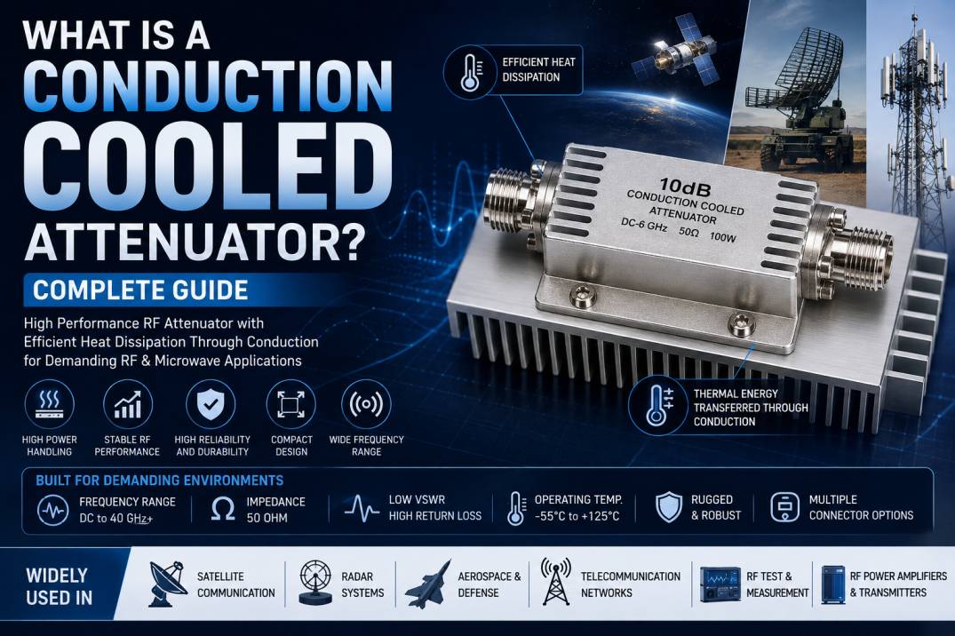
A Conduction Cooled Attenuator is a specialized RF and microwave component designed to reduce signal power while efficiently transferring the heat generated by RF energy into a controlled thermal path. Unlike conventional attenuators that may rely on air cooling or natural convection, conduction cooled attenuators are specifically designed to transfer heat through direct physical contact with a chassis, heat sink, cold plate, or other thermal management structure.
These attenuators are widely used in aerospace, defense, satellite communication, radar, telecommunications, RF power amplifiers, microwave test equipment, and other high-performance RF systems where compact size, high reliability, and efficient thermal management are essential.
The main purpose of a conduction cooled attenuator is to perform two functions simultaneously: provide accurate RF signal attenuation and remove the heat generated by the internal resistive attenuation network.
What Is a Conduction Cooled RF Attenuator?
A conduction cooled RF attenuator is a passive RF device that reduces signal power while transferring the resulting thermal energy through a conductive thermal path.
When an RF signal passes through the attenuator, part of the signal energy is absorbed by internal resistive elements. This absorbed energy is converted into heat. The heat is then transferred through the attenuator’s internal structure and metal housing into the mounting surface, chassis, heat sink, or cold plate.
This design makes conduction cooled attenuators particularly useful in systems where airflow is limited or where fans cannot be used.
How Does a Conduction Cooled Attenuator Work?
A conduction cooled attenuator operates using two interconnected principles: RF attenuation and thermal conduction.
The incoming RF signal enters the attenuator through the input connector. The internal resistive network reduces the signal by a predetermined attenuation value. The portion of RF power absorbed by the resistive elements is converted into heat.
This heat travels through the internal conductive structure and housing before reaching the external cooling surface.
The basic thermal path can be understood as:
RF Signal → Resistive Network → Heat Generation → Metal Housing → Thermal Interface → Chassis or Cold Plate → Heat Removal
An effective thermal path helps keep the internal temperature within the required operating range and supports stable RF performance.
Why Is Thermal Management Important in RF Attenuators?
RF attenuation inherently generates heat because an attenuator absorbs part of the incoming RF power.
In a high-power RF application, the amount of absorbed energy can become substantial. If this heat is not removed efficiently, the temperature of the attenuator can rise and affect both electrical and mechanical performance.
Excessive temperature can cause:
- Resistance changes
- Attenuation variation
- Increased VSWR
- Reduced power-handling capability
- Thermal stress
- Connector degradation
- Reduced component life
- Unstable RF performance
Conduction cooling provides a controlled path for transferring this heat away from the resistive elements.
Key Components of a Conduction Cooled Attenuator
Resistive Attenuation Network
The resistive network determines the attenuation value and absorbs a portion of the incoming RF power.
Common attenuation values include 1 dB, 2 dB, 3 dB, 5 dB, 6 dB, 10 dB, 15 dB, 20 dB, and 30 dB.
RF Connectors
RF connectors provide the electrical interface between the attenuator and the surrounding RF system.
Depending on the frequency and application, conduction cooled attenuators may use SMA, N-Type, TNC, 2.92 mm, 2.4 mm, SMP, SMPM, or other specialized RF connectors.
Metal Housing
The metal housing provides mechanical protection while also acting as an important part of the thermal conduction path.
Aluminum, copper, brass, and specialized alloys may be used depending on the required thermal, mechanical, and RF performance.
Thermal Interface
The thermal interface connects the attenuator to the equipment chassis, heat sink, cold plate, or other cooling structure.
A properly designed thermal interface minimizes thermal resistance and improves heat transfer.
Mounting Structure
Mounting features allow the attenuator to be securely attached to the equipment platform.
Proper mechanical mounting is essential because physical contact directly affects thermal performance.
Advantages of Conduction Cooled Attenuators
Efficient Heat Dissipation
Conduction cooling provides a direct thermal path for transferring heat from the resistive elements to the external cooling structure.
Stable RF Performance
Maintaining controlled operating temperatures helps provide more consistent attenuation, impedance, VSWR, and other RF characteristics.
High Power Handling
Specialized conduction cooled attenuators can be designed for high-power RF applications where conventional compact attenuators may not provide sufficient thermal performance.
Compact Packaging
Because conduction cooling does not depend primarily on airflow, it can support compact RF assemblies and densely packaged electronic systems.
High Reliability
Effective thermal management helps reduce excessive temperature and thermal stress, supporting long-term component reliability.
Suitable for Sealed Systems
Conduction cooled attenuators are particularly useful in sealed or enclosed electronic systems where forced-air cooling is unavailable.
Aerospace and Defense Compatibility
Their compact construction, thermal performance, and rugged mechanical design make them suitable for demanding aerospace and defense applications.
Types of Conduction Cooled Attenuators
Fixed Conduction Cooled Attenuator
A fixed attenuator provides a predetermined attenuation value such as 3 dB, 6 dB, 10 dB, or 20 dB.
These components are commonly used for signal-level control, impedance matching, isolation, and RF system protection.
High Power Conduction Cooled Attenuator
High-power conduction cooled attenuators are designed to absorb significant RF energy while transferring the resulting heat into a suitable cooling structure.
They are commonly used in radar, RF transmitters, microwave systems, and high-power test equipment.
Low PIM Conduction Cooled Attenuator
Low PIM conduction cooled attenuators are designed for communication systems where unwanted passive intermodulation products must be minimized.
Broadband Conduction Cooled Attenuator
Broadband versions are designed to maintain controlled attenuation and impedance performance over a wide frequency range.
Custom Conduction Cooled Attenuator
Custom attenuators can be developed according to specific requirements for frequency, attenuation, power handling, connector type, mounting arrangement, dimensions, and thermal interface.
Important Electrical Specifications
Frequency Range
Frequency range defines the RF spectrum over which the attenuator is designed to provide its specified electrical performance.
Attenuation
Attenuation defines how much the RF signal is reduced and is normally expressed in decibels.
Impedance
Most RF conduction cooled attenuators are designed for a 50 Ohm impedance.
VSWR
Voltage Standing Wave Ratio indicates the quality of impedance matching between the attenuator and the RF transmission system.
Return Loss
Return loss indicates the amount of RF signal reflected back toward the source. Higher return loss generally indicates better impedance matching.
Insertion Loss
Insertion loss represents the additional signal loss introduced by the component beyond its intended attenuation characteristics.
Power Rating
Power rating defines the amount of RF power the attenuator can safely handle under specified operating and thermal conditions.
Power ratings may include continuous-wave power, average power, peak power, or pulsed power.
Important Thermal Specifications
Thermal Resistance
Thermal resistance indicates how effectively heat moves from the attenuator into the external cooling structure. Lower thermal resistance generally provides more effective heat transfer.
Mounting Temperature
The temperature of the chassis or cold plate directly affects the thermal operating margin of the attenuator.
Operating Temperature
The attenuator must remain within its specified operating temperature range to maintain reliable electrical and mechanical performance.
Thermal Interface Quality
The quality of the physical interface between the attenuator and cooling surface can significantly influence thermal performance.
Heat Spreading
The attenuator housing should distribute heat effectively and minimize localized hot spots.
Applications of Conduction Cooled Attenuators
Aerospace Systems
Aerospace electronics often require compact, lightweight, and highly reliable components with efficient thermal management.
Conduction cooling is valuable where conventional fan-based cooling is impractical.
Defense Electronics
Defense systems use conduction cooled attenuators in RF transmitters, radar systems, communication equipment, electronic warfare systems, and specialized RF test platforms.
Radar Systems
Radar equipment can generate substantial RF power. Conduction cooled attenuators help control RF signal levels while providing an effective thermal path.
Satellite Communication
Satellite and space electronics have demanding thermal management requirements. Conduction cooled components can be integrated with spacecraft thermal structures where conventional airflow is not available.
RF Power Amplifiers
Conduction cooled attenuators can be used around RF power amplifier stages for signal-level control, isolation, testing, and protection.
Microwave Test Equipment
High-performance microwave test systems require accurate signal control and stable electrical characteristics. Conduction cooled attenuators can be used where significant RF power must be absorbed.
Telecommunications
They can be used in communication equipment, RF distribution systems, and infrastructure where compact packaging and thermal management are important.
Electronic Warfare Systems
Electronic warfare equipment can operate with high-frequency and high-power RF signals, making efficient heat removal an important part of system design.
Conduction Cooling and Power Handling
Power handling is closely related to thermal design.
When a conduction cooled attenuator absorbs RF power, that energy becomes heat. The cooling system must then remove that heat efficiently enough to maintain the component within its safe operating temperature.
Engineers should evaluate:
- Input RF power
- Attenuation value
- Operating frequency
- Duty cycle
- Pulse characteristics
- Mounting temperature
- Thermal resistance
- Cooling surface
- Maximum allowable temperature
Therefore, an attenuator should never be selected solely according to its attenuation value. Electrical and thermal specifications must be considered together.
Materials Used in Conduction Cooled Attenuators
Aluminum
Aluminum offers a useful combination of low weight, mechanical strength, and thermal conductivity.
Copper
Copper provides excellent thermal conductivity and may be selected when efficient heat transfer is a major requirement.
Brass
Brass is widely used in RF mechanical structures and connector components because of its machinability, strength, and electrical properties.
Plated Materials
Gold, nickel, silver, and other plating systems may be used to improve conductivity, corrosion resistance, durability, and connector performance.
Design Considerations for Conduction Cooled Attenuators
Engineers should evaluate both RF and thermal requirements during the design process.
Important considerations include:
- Operating frequency
- Attenuation value
- RF input power
- Impedance
- VSWR
- Return loss
- Thermal resistance
- Mounting surface
- Operating temperature
- Environmental conditions
- Mechanical dimensions
- Weight
- Connector type
- Vibration requirements
- Shock requirements
- Thermal cycling
A successful design requires a balance between electrical performance, thermal performance, mechanical reliability, and environmental durability.
How to Choose the Right Conduction Cooled Attenuator
Determine the Frequency Range
Select an attenuator that supports the complete operating frequency range of the RF system.
Select the Required Attenuation
Determine the exact amount of signal reduction required for the application.
Calculate Power Dissipation
Estimate how much RF power will be absorbed by the attenuator and converted into heat.
Check Thermal Conditions
Evaluate the chassis temperature, cold plate temperature, ambient conditions, thermal interface, and available cooling capacity.
Select the Correct Connector
Choose an RF connector that matches the system interface and frequency requirements.
Verify VSWR and Return Loss
For precision RF systems, impedance matching should be carefully evaluated.
Consider Mechanical Requirements
Check dimensions, mounting holes, weight, connector orientation, and available installation space.
Consider Environmental Requirements
For aerospace and defense applications, evaluate temperature, vibration, shock, humidity, altitude, corrosion, and thermal cycling requirements.
Conduction Cooled Attenuator vs Standard RF Attenuator
A standard RF attenuator primarily focuses on signal attenuation and conventional heat dissipation.
A conduction cooled attenuator combines signal attenuation with a dedicated conductive thermal path.
Standard RF Attenuator
- Primarily designed for RF attenuation
- May rely on air or natural convection
- Suitable for many low- and medium-power applications
- Simple installation
Conduction Cooled Attenuator
- Designed for RF attenuation and thermal conduction
- Transfers heat directly to a cooling structure
- Suitable for thermally constrained systems
- Useful for high-power applications
- Suitable for sealed and compact equipment
Common Problems in Conduction Cooled Attenuator Applications
Poor Thermal Contact
An uneven or poor-quality mounting interface can increase thermal resistance and reduce cooling efficiency.
Insufficient Cooling Capacity
The external cooling system must be capable of removing the heat generated by the attenuator.
Excessive Input Power
Operating above the specified RF power rating can cause overheating and permanent damage.
Incorrect Mounting
Improper mechanical mounting can reduce the effectiveness of the thermal path.
Inadequate Thermal Interface
Incorrect thermal interface materials or excessive interface thickness can increase thermal resistance.
High Operating Temperature
High chassis or ambient temperatures can significantly reduce the available thermal margin.
Best Practices for Installation
For reliable operation:
- Use a clean and flat mounting surface.
- Ensure proper mechanical contact.
- Follow the manufacturer’s recommended mounting procedure.
- Use the specified thermal interface material.
- Avoid unnecessary thermal interface thickness.
- Verify RF connector compatibility.
- Operate within the specified power rating.
- Monitor temperature in high-power applications.
- Ensure adequate heat removal from the chassis or cold plate.
- Inspect connectors and mounting hardware periodically.
Benefits in Modern RF Systems
Modern RF systems are becoming smaller while simultaneously handling higher frequencies and greater power densities.
This creates significant thermal management challenges.
Conduction cooled attenuators help address these challenges by combining:
- Compact packaging
- Controlled RF attenuation
- Efficient heat transfer
- Stable RF performance
- High-power capability
- Reduced dependence on airflow
- Rugged construction
- Reliable operation
These characteristics make conduction cooled attenuators valuable for advanced RF and microwave systems.
Why Choose a High-Quality Conduction Cooled Attenuator?
A high-quality conduction cooled attenuator should provide consistent electrical and thermal performance.
Important characteristics include:
- Precision attenuation
- Stable 50 Ohm impedance
- Low VSWR
- High return loss
- Reliable power handling
- Efficient heat transfer
- High-quality RF connectors
- Rugged housing
- Precision machining
- Reliable thermal interface
- Long-term operational stability
For demanding applications, both electrical and thermal specifications should be verified before selecting the component.
Conclusion
A Conduction Cooled Attenuator is an advanced RF component designed to provide precise signal attenuation while efficiently transferring internally generated heat into a chassis, heat sink, cold plate, or other thermal management structure.
Its ability to combine RF signal control with efficient thermal management makes it particularly useful for high-power and thermally constrained systems.
Conduction cooled attenuators are widely used in aerospace, defense, radar, satellite communication, telecommunications, RF power amplifiers, microwave test equipment, and electronic warfare systems.
When selecting a conduction cooled attenuator, engineers should consider frequency range, attenuation, impedance, VSWR, return loss, power rating, thermal resistance, mounting temperature, connector type, dimensions, and environmental requirements.
Proper thermal mounting is equally important because actual power-handling capability depends not only on the attenuator itself but also on the effectiveness of the complete thermal path.
As RF systems continue to demand higher power density, smaller form factors, and greater reliability, conduction cooled attenuators provide an effective solution for maintaining both RF performance and thermal stability.
Frequently Asked Questions About Conduction Cooled Attenuators
What is a conduction cooled attenuator?
A conduction cooled attenuator is an RF component that reduces signal power while transferring the heat generated by absorbed RF energy through a conductive thermal path to a chassis, heat sink, or cold plate.
How does a conduction cooled attenuator work?
It uses an internal resistive network to attenuate the RF signal. The absorbed RF energy becomes heat, which is transferred through the metal housing and mounting interface into an external cooling structure.
Why are conduction cooled attenuators used?
They are used when RF systems require controlled signal attenuation and efficient heat removal, particularly where airflow is restricted or unavailable.
Where are conduction cooled attenuators used?
They are commonly used in aerospace, defense, radar, satellite communication, telecommunications, RF power amplifiers, microwave test equipment, and electronic warfare systems.
What is the difference between conduction cooled and air cooled attenuators?
Air cooled attenuators primarily release heat through surrounding air, while conduction cooled attenuators transfer heat directly through a physical thermal path to a chassis, heat sink, or cold plate.
Can conduction cooled attenuators handle high RF power?
Yes. Specialized conduction cooled attenuators can be designed for high-power applications. However, actual power handling depends on frequency, attenuation, duty cycle, mounting temperature, thermal resistance, and cooling conditions.
What impedance is commonly used?
Most RF conduction cooled attenuators use a 50 Ohm impedance, although specialized configurations may be available.
What attenuation values are available?
Common values include 3 dB, 6 dB, 10 dB, 20 dB, and 30 dB. Custom attenuation values can also be developed for specific RF applications.
Why is thermal resistance important?
Thermal resistance determines how efficiently heat can move from the attenuator into the cooling structure. Lower thermal resistance generally allows more effective heat removal.
Can conduction cooled attenuators be customized?
Yes. They can be customized for frequency range, attenuation, power handling, connector type, mechanical dimensions, mounting configuration, thermal interface, and environmental requirements.
What factors determine the power rating?
Power rating depends on RF frequency, attenuation, signal type, duty cycle, mounting temperature, thermal resistance, housing design, and the capability of the external cooling system.
Are conduction cooled attenuators suitable for aerospace applications?
Yes. Their compact construction and dependence on conductive thermal paths make them suitable for many aerospace systems where airflow, size, weight, and thermal management are important considerations.










