
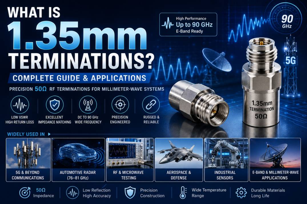
1.35mm Terminations are precision RF termination components designed for high-frequency and millimeter-wave systems operating in the E-band and other demanding microwave applications. They are used to absorb RF energy at the end of a transmission path, preventing unwanted signal reflections and maintaining a controlled impedance environment.
The 1.35mm connector interface was developed to bridge the performance gap between larger 1.85mm connectors and smaller 1.00mm connectors. Modern 1.35mm RF interfaces are designed for applications reaching up to approximately 90 GHz, making them particularly useful for E-band communications, automotive radar, 5G systems, high-frequency testing, and advanced millimeter-wave instrumentation.
1.35mm RF Terminations are generally designed around a 50 Ohm impedance and provide a precision load for high-frequency measurement and communication systems. TE Connectivity, for example, specifies 1.35mm RF interfaces with 50 Ohm impedance and operating frequencies up to 90 GHz.
What Is a 1.35mm RF Termination?
A 1.35mm RF Termination is a passive microwave component that provides a matched load at the end of a 1.35mm coaxial transmission line or unused RF port.
Its primary function is to absorb incoming RF energy and minimize the amount of energy reflected toward the signal source.
In a high-frequency system, even a small impedance discontinuity can create significant signal errors. This becomes increasingly important as frequencies approach the millimeter-wave range.
A precision 1.35mm termination therefore helps maintain:
- 50 Ohm impedance
- Low VSWR
- High return loss
- Stable RF measurements
- Reduced signal reflections
- Consistent measurement repeatability
Why Was the 1.35mm Connector Developed?
High-frequency RF systems have traditionally used interfaces such as 1.85mm and 1.00mm connectors.
A 1.85mm connector can support frequencies around the V-band range, while 1.00mm connectors extend into the W-band. The 1.35mm interface was introduced to fill the gap between these two connector sizes and provide an alternative for applications requiring performance up to approximately 90 GHz.
The larger physical dimensions compared with a 1.00mm connector can also make the 1.35mm interface more mechanically robust for certain applications.
How Does a 1.35mm Termination Work?
When an RF signal travels through a coaxial transmission line, it expects to see a specific impedance.
For most 1.35mm RF systems, this impedance is 50 Ohms.
If the transmission line encounters an unmatched load, part of the signal energy is reflected back toward the source. At very high frequencies, these reflections can significantly affect measurement accuracy and system performance.
A 1.35mm termination presents a precision matched load to the transmission line.
The incoming RF energy is absorbed by the termination rather than being reflected back into the system.
This helps provide:
- Better impedance matching
- Lower VSWR
- Improved return loss
- More accurate measurements
- Stable RF system operation
Key Features of 1.35mm Terminations
90 GHz High-Frequency Capability
The 1.35mm interface is particularly suited to E-band applications and can support frequencies up to approximately 90 GHz in suitable designs.
50 Ohm Impedance
Precision 1.35mm RF connectors are commonly designed for 50 Ohm systems. This allows them to integrate with high-frequency measurement equipment, coaxial cables, adapters, and other microwave components.
Low VSWR
A high-quality termination is designed to provide a low voltage standing wave ratio across its specified frequency range.
Lower VSWR means less reflected energy and improved measurement conditions.
High Return Loss
High return loss indicates that only a small amount of the incident signal is reflected toward the source.
This is particularly important for precision vector network analyzer measurements.
Precision Mechanical Design
At frequencies approaching 90 GHz, dimensional accuracy becomes extremely important.
The internal geometry of the connector, center conductor, dielectric structure, and outer conductor must be precisely controlled to maintain predictable electrical performance.
High Mechanical Reliability
Modern 1.35mm connector designs are intended for demanding test and measurement environments. Rosenberger’s RPC-1.35 series, for example, specifies a mechanical design rated for at least 3,000 mating cycles.
1.35mm Termination Construction
A precision 1.35mm termination typically includes several carefully engineered components.
Precision RF Resistor
The internal resistive element provides the matched load required to absorb RF energy.
Center Conductor
The center conductor carries the RF signal into the termination and must maintain precise geometry.
Dielectric Material
A low-loss dielectric supports the center conductor while minimizing unwanted dielectric losses.
Outer Conductor
The outer conductor provides the RF return path and electromagnetic shielding.
Precision Connector Housing
The housing maintains the mechanical dimensions required for high-frequency performance.
Typical 1.35mm Termination Specifications
Specifications vary according to manufacturer and product design, but a high-performance 1.35mm RF termination may include:
| Parameter | Typical Specification |
|---|---|
| Connector Type | 1.35mm RF Termination |
| Impedance | 50 Ohm |
| Frequency Range | DC to 90 GHz |
| Interface | 1.35mm |
| Coupling | Threaded |
| Application | Millimeter-Wave RF |
| VSWR | Low, frequency dependent |
| Return Loss | High, frequency dependent |
| Connector Material | Stainless Steel or Precision Alloy |
| Contact Plating | Gold or other RF-grade plating |
| Application Temperature | Product dependent |
| Mounting | Coaxial, cable, test fixture or instrument interface |
The exact electrical specifications should always be verified against the manufacturer’s individual datasheet.
1.35mm Terminations vs 1.85mm Terminations
The 1.35mm and 1.85mm interfaces are both used for high-frequency RF applications, but they target different frequency requirements.
1.35mm Terminations
1.35mm terminations are designed for applications extending into the E-band and can support frequencies up to approximately 90 GHz in suitable products.
1.85mm Terminations
1.85mm connectors are generally associated with applications up to approximately 67 GHz.
The 1.35mm interface therefore provides a useful option for applications above the typical 1.85mm operating range without moving all the way to the smaller 1.00mm interface.
1.35mm Terminations vs 1.00mm Terminations
The 1.00mm connector is designed for even higher-frequency applications, with systems reaching approximately 110 GHz.
However, the smaller interface can be more mechanically delicate.
The 1.35mm connector offers a middle ground:
- Higher frequency capability than many 1.85mm systems
- Larger interface dimensions than 1.00mm
- Suitable performance up to approximately 90 GHz
- Strong suitability for E-band applications
- Useful for demanding RF test environments
This makes 1.35mm terminations particularly attractive where mechanical robustness and high-frequency performance must be balanced.
Applications of 1.35mm Terminations
E-Band Communication
E-band systems operate in the high-frequency millimeter-wave region and require precision RF components.
1.35mm interfaces are specifically suited to E-band applications extending toward 90 GHz.
Automotive Radar
Automotive radar systems commonly operate around the 76–81 GHz region.
1.35mm RF technology is particularly relevant to radar development, testing, and measurement applications around 79 GHz.
5G and Beyond-5G Systems
High-frequency communications research and advanced 5G infrastructure can require millimeter-wave test equipment and components.
1.35mm connectors are used in high-frequency applications including 5G front-haul equipment and related E-band technologies.
RF and Microwave Testing
1.35mm terminations can be used with:
- Vector Network Analyzers
- Signal generators
- Spectrum analyzers
- Power meters
- Millimeter-wave test fixtures
- Calibration systems
- RF test cables
Industrial Sensors
Millimeter-wave sensors require highly controlled RF interfaces.
1.35mm technology is used in industrial sensing applications where high-frequency signal integrity is important.
Aerospace and Defense
Advanced radar, electronic warfare, communication, and RF test systems can require precision millimeter-wave components.
Research and Development
Universities, laboratories, semiconductor companies, and RF research organizations can use 1.35mm terminations for high-frequency characterization and measurement.
Advantages of 1.35mm Terminations
Excellent Signal Integrity
The precision impedance design minimizes unwanted reflections.
High-Frequency Operation
Support for frequencies approaching 90 GHz makes 1.35mm terminations suitable for E-band and millimeter-wave systems.
Improved Measurement Accuracy
Matched terminations provide controlled measurement environments for high-frequency instruments.
Low Reflection
A properly specified termination absorbs incident RF energy and reduces reflected power.
Mechanical Robustness
The 1.35mm interface provides a practical compromise between very small high-frequency interfaces and larger connector designs.
Repeatable Connections
Precision mechanical interfaces help provide consistent electrical performance during repeated measurements.
Importance of VSWR in 1.35mm Terminations
VSWR, or Voltage Standing Wave Ratio, is an important parameter when evaluating RF terminations.
A perfect matched load has a VSWR of 1:1.
As impedance mismatch increases, VSWR increases.
At frequencies approaching 90 GHz, even small mechanical imperfections can influence RF performance. Therefore, precision manufacturing and accurate connector geometry are critical when designing 1.35mm terminations.
Importance of Return Loss
Return loss describes how much of the incident RF signal is reflected back toward the source.
A higher return loss generally indicates better impedance matching.
For precision millimeter-wave measurement systems, high return loss is desirable because it reduces measurement uncertainty and unwanted interaction between the source, cable, termination, and device under test.
1.35mm Terminations for VNA Measurements
Vector Network Analyzers are commonly used to characterize high-frequency RF components.
During a VNA measurement, unused ports and test fixtures may need appropriate terminations to create a controlled RF environment.
A precision 1.35mm termination can help:
- Reduce reflections
- Improve calibration conditions
- Maintain port impedance
- Increase measurement repeatability
- Reduce measurement errors
This is especially important when measurements extend into the E-band.
How to Choose the Right 1.35mm Termination
Check the Frequency Range
Confirm that the termination supports the highest operating frequency of your system.
For E-band applications, a termination rated appropriately for frequencies approaching 90 GHz may be required.
Verify 50 Ohm Impedance
Most precision 1.35mm RF systems use 50 Ohm impedance. Confirm compatibility before installation.
Check Connector Gender
Select the appropriate male or female configuration for the equipment or cable interface.
Check Power Handling
High-frequency terminations have specific maximum power ratings. Never assume that a small precision termination can handle high RF power.
Check VSWR and Return Loss
For measurement applications, these specifications are particularly important.
Verify Mechanical Compatibility
Check the connector interface, coupling mechanism, dimensions, and mating requirements before connecting components.
Common Mistakes When Using 1.35mm Terminations
Several mistakes can negatively affect millimeter-wave performance.
- Using the wrong impedance
- Using a termination with insufficient frequency rating
- Exceeding the power rating
- Using incompatible connector interfaces
- Applying excessive mating torque
- Contaminating the RF interface
- Scratching the mating surfaces
- Using an uncertified or poorly characterized termination
- Ignoring calibration requirements
Maintenance of 1.35mm RF Terminations
Because 1.35mm interfaces are precision millimeter-wave components, careful handling is essential.
Keep mating surfaces clean and protected from dust and contamination.
Avoid unnecessary mating and unmating cycles.
Use the manufacturer’s recommended torque specifications.
Inspect the connector interface before every critical measurement.
Store unused terminations with appropriate protective caps.
Do not force the connector if the mating interfaces do not align correctly.
Why Precision Matters at 90 GHz
At millimeter-wave frequencies, physical dimensions become extremely important.
Small variations in:
- Center conductor diameter
- Dielectric geometry
- Connector alignment
- Surface finish
- Contact dimensions
- Connector gap
can influence impedance and RF performance.
This is why high-frequency 1.35mm terminations require precision machining, controlled materials, accurate assembly, and proper quality inspection.
1.35mm Terminations for E-Band Applications
The E-band region is particularly important for high-capacity wireless communication, sensing, radar, and research applications.
The 1.35mm connector was developed specifically to address applications requiring performance beyond conventional 1.85mm interfaces while offering a more substantial physical interface than 1.00mm connectors.
As a result, 1.35mm terminations are well suited to modern millimeter-wave test and measurement environments.
Future of 1.35mm RF Technology
The demand for higher-frequency RF systems continues to grow as wireless communication, automotive radar, industrial sensing, and advanced instrumentation become more sophisticated.
The 1.35mm interface provides an important option between established 1.85mm and 1.00mm connector families.
Rosenberger identifies applications including 5G, E-band industrial sensors, automotive millimeter-wave sensors, and WLAN technologies among the areas addressed by its RPC-1.35 platform.
Conclusion
1.35mm Terminations are precision RF components designed for demanding high-frequency and millimeter-wave applications. With 50 Ohm impedance and operating capabilities reaching approximately 90 GHz in suitable designs, they provide a practical solution for E-band communication, automotive radar, 5G-related systems, RF testing, industrial sensors, aerospace, defense, and research.
The 1.35mm interface occupies an important position between 1.85mm and 1.00mm technologies, combining high-frequency capability with a mechanically practical interface.
For reliable millimeter-wave performance, it is essential to select a 1.35mm termination according to frequency range, impedance, VSWR, return loss, power handling, connector gender, mechanical compatibility, and application requirements.
Frequently Asked Questions About 1.35mm Terminations
What is a 1.35mm termination?
A 1.35mm termination is a precision RF load designed to absorb RF energy and minimize signal reflections in 1.35mm coaxial systems.
What frequency does a 1.35mm termination support?
Many 1.35mm RF products are designed to operate up to approximately 90 GHz, making them suitable for E-band applications.
What is the impedance of a 1.35mm termination?
Precision 1.35mm RF interfaces are commonly designed with a 50 Ohm impedance.
Why was the 1.35mm connector developed?
It was developed to fill the performance gap between 1.85mm connectors and 1.00mm connectors, particularly for applications requiring frequencies above approximately 70 GHz and up to 90 GHz.
Where are 1.35mm terminations used?
They are used in E-band communication, automotive radar, 5G-related systems, industrial sensors, RF laboratories, aerospace, defense, and millimeter-wave test and measurement applications.
Are 1.35mm terminations suitable for automotive radar?
Yes. The 1.35mm interface is particularly relevant to millimeter-wave automotive radar applications around the 79 GHz region.
What is the difference between 1.35mm and 1.85mm terminations?
The 1.35mm interface extends higher in frequency, with suitable products reaching approximately 90 GHz, while 1.85mm interfaces are commonly used up to around 67 GHz.
What is the difference between 1.35mm and 1.00mm terminations?
A 1.00mm interface can extend to approximately 110 GHz, while 1.35mm interfaces commonly reach approximately 90 GHz. The 1.35mm interface offers a larger physical interface and can be a more mechanically practical option for applications up to 90 GHz.
Are 1.35mm terminations used with Vector Network Analyzers?
Yes. They are suitable for high-frequency VNA testing, calibration environments, RF characterization, and millimeter-wave measurement systems.
What should I check before buying a 1.35mm termination?
Check the frequency range, 50 Ohm impedance, connector gender, VSWR, return loss, power rating, mechanical interface, environmental specifications, and manufacturer’s calibration or measurement data where applicable.










