
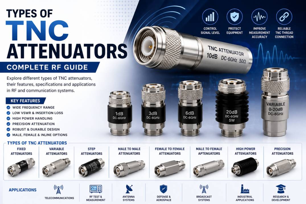
TNC attenuators are important RF components used to reduce signal power in coaxial transmission systems while maintaining controlled impedance and predictable RF performance. They are widely used in telecommunications, wireless communication, RF testing, laboratory instrumentation, antennas, radio systems, defense electronics, and other high-frequency applications.
The term TNC refers to Threaded Neill-Concelman, a threaded version of the BNC connector family. The threaded coupling mechanism provides a more secure connection than a bayonet-style connection and makes TNC connectors suitable for applications where vibration, mechanical stability, and reliable RF connectivity are important.
A TNC attenuator combines the mechanical interface of a TNC connector with an RF attenuation network. Depending on the design, TNC attenuators can provide a fixed attenuation value or adjustable attenuation over a specified range.
Common TNC attenuator values include 1 dB, 2 dB, 3 dB, 6 dB, 10 dB, 20 dB, and higher values. The correct attenuation level depends on the RF system, signal power, frequency range, impedance, and application requirements.
This guide explains the different types of TNC attenuators, their construction, working principle, specifications, applications, advantages, selection criteria, and common RF engineering considerations.
What Is a TNC Attenuator?
A TNC attenuator is a passive RF device that reduces the power level of an RF signal while providing a controlled impedance connection between two RF ports.
Unlike an amplifier, which increases signal power, an attenuator intentionally introduces a known amount of insertion loss.
For example, a 10 dB TNC attenuator reduces the RF signal power by 10 dB.
TNC attenuators are commonly designed around a 50-ohm impedance, although the actual impedance should always be verified from the manufacturer’s specifications.
A TNC attenuator generally consists of:
- TNC connector interface
- Resistive attenuation network
- RF transmission path
- Mechanical housing
- Insulating dielectric
- Center conductor
- Ground/shield structure
The attenuation network is carefully designed to provide the specified attenuation while maintaining acceptable VSWR, return loss, insertion loss, and power-handling capability.
What Does a TNC Connector Mean?
TNC stands for Threaded Neill-Concelman.
A TNC connector is mechanically similar to a BNC connector but uses a threaded coupling mechanism instead of a bayonet coupling system.
The threaded interface provides improved mechanical security and can be beneficial in environments involving vibration or movement.
TNC connectors are available in male and female configurations and can be used with RF cables, adapters, antennas, test equipment, and attenuators.
How Does a TNC Attenuator Work?
A TNC attenuator works by introducing a controlled amount of resistance into the RF signal path.
The attenuation network absorbs part of the RF power and reduces the signal level delivered to the output port.
For an ideal matched attenuator, the relationship between input and output power is expressed in decibels.
The attenuation can be represented as:
Attenuation (dB) = 10 log10(Pin / Pout)
Where:
- Pin = Input RF power
- Pout = Output RF power
For example, a 3 dB attenuator delivers approximately half the input power to the output.
A 10 dB attenuator delivers approximately one-tenth of the input power.
A 20 dB attenuator delivers approximately one-hundredth of the input power.
Why Are TNC Attenuators Used?
TNC attenuators are used to control RF signal levels within a communication or measurement system.
Important applications include:
- Reducing excessive signal levels
- Protecting sensitive RF receivers
- Matching signal levels
- Preventing receiver overload
- Improving test-system accuracy
- Controlling RF power during testing
- Reducing signal reflections caused by mismatched interfaces
- Creating controlled signal levels for calibration
- Providing isolation between RF components
Main Types of TNC Attenuators
TNC attenuators can be classified according to attenuation behavior, connector configuration, power rating, construction, frequency range, and application.
The major types include:
- Fixed TNC Attenuators
- Variable TNC Attenuators
- Step TNC Attenuators
- Male-to-Male TNC Attenuators
- Female-to-Female TNC Attenuators
- Male-to-Female TNC Attenuators
- Inline TNC Attenuators
- High-Power TNC Attenuators
- Precision TNC Attenuators
- Broadband TNC Attenuators
- Low-PIM TNC Attenuators
- Termination-Style TNC Attenuators
- Programmable or Switched Attenuator Configurations
1. Fixed TNC Attenuators
A fixed TNC attenuator provides a predetermined attenuation value that cannot be adjusted during operation.
Common attenuation values include:
- 1 dB
- 2 dB
- 3 dB
- 5 dB
- 6 dB
- 10 dB
- 15 dB
- 20 dB
- 30 dB
The exact available values depend on the manufacturer and frequency range.
Advantages of Fixed TNC Attenuators
- Simple construction
- Stable attenuation
- Compact size
- High reliability
- Easy installation
- Repeatable RF performance
- Suitable for permanent installations
Fixed attenuators are often preferred in production RF systems because they do not contain moving parts.
2. Variable TNC Attenuators
A variable TNC attenuator allows the attenuation level to be adjusted over a specified range.
For example, a variable attenuator may provide an adjustable attenuation range from a low value to a higher value.
Variable attenuators are useful when the RF signal level needs to be changed during testing or system development.
Applications
- RF laboratories
- Communication testing
- Antenna testing
- Transmitter testing
- Receiver testing
- Calibration systems
- Research and development
Advantages
- Adjustable signal level
- Flexible testing
- Useful for RF characterization
- Reduces the need for multiple fixed attenuators
3. Step TNC Attenuators
A step attenuator provides predefined attenuation settings.
Unlike a continuously variable attenuator, the attenuation changes in specific steps.
For example, a step attenuator may provide settings such as:
- 0 dB
- 1 dB
- 2 dB
- 4 dB
- 8 dB
- 10 dB
- 20 dB
Depending on the design, multiple attenuation sections can be combined to create different total attenuation values.
Applications
Step TNC attenuators are commonly useful in:
- RF test equipment
- Signal generators
- Receiver testing
- Laboratory setups
- Automated RF measurements
4. TNC Male-to-Male Attenuator
A male-to-male TNC attenuator has male TNC connectors on both sides.
It can directly connect two female TNC interfaces while providing the specified attenuation.
Applications
- RF equipment interconnection
- Test systems
- Coaxial cable interfaces
- Antenna systems
- RF measurement setups
Connector gender should always be checked before selecting an attenuator.
5. TNC Female-to-Female Attenuator
A female-to-female TNC attenuator contains female TNC interfaces on both sides.
This configuration is useful when connecting two male TNC interfaces while maintaining controlled RF attenuation.
Benefits
- Convenient equipment interconnection
- Controlled attenuation
- Secure threaded connection
- Easy integration into modular RF systems
6. TNC Male-to-Female Attenuator
A male-to-female TNC attenuator provides one male and one female TNC interface.
This configuration can simplify installation when the connected RF equipment has different connector genders.
Applications
- RF test equipment
- Cellular systems
- Wireless infrastructure
- Antenna connections
- Cable assemblies
7. Inline TNC Attenuators
An inline TNC attenuator is installed directly into the RF transmission path.
It typically has a compact cylindrical or barrel-style design.
The inline configuration makes it easy to add attenuation without modifying the RF cable assembly.
Applications
- RF cable systems
- Test benches
- Antenna feed systems
- Wireless communication equipment
- Signal-level adjustment
8. High-Power TNC Attenuators
High-power TNC attenuators are specifically designed to handle higher RF power levels.
The attenuation network generates heat because a portion of the RF energy is dissipated within the attenuator.
Therefore, high-power designs require appropriate thermal management.
Important Specifications
- Maximum input power
- Average power
- Peak power
- Operating temperature
- Frequency range
- VSWR
- Connector rating
- Thermal resistance
High-power TNC attenuators can be used in:
- RF transmitters
- Radio systems
- Broadcast equipment
- Cellular infrastructure
- Defense electronics
- Laboratory test systems
9. Precision TNC Attenuators
Precision TNC attenuators are designed for applications where accurate and repeatable attenuation is important.
They are commonly manufactured using controlled RF materials and precision machining techniques.
Applications
- RF calibration
- Vector network analyzer testing
- Spectrum analyzer testing
- Signal generator measurements
- Research laboratories
- RF characterization
Precision attenuators generally emphasize low VSWR, stable attenuation, repeatability, and predictable frequency response.
10. Broadband TNC Attenuators
Broadband TNC attenuators operate across a relatively wide frequency range.
They are useful in RF systems where a single attenuator must work across multiple frequencies.
Applications
- Broadband communication
- RF test systems
- Laboratory instrumentation
- Wireless communication
- Antenna testing
When selecting a broadband TNC attenuator, the specified attenuation accuracy should be evaluated across the complete frequency range rather than at only one frequency.
11. Low-PIM TNC Attenuators
Low-PIM attenuators are designed to minimize passive intermodulation products.
PIM can be a significant concern in high-performance cellular and RF infrastructure because nonlinear behavior in passive components can generate unwanted frequencies.
Low-PIM TNC attenuators can be useful in:
- Cellular infrastructure
- Distributed antenna systems
- RF signal distribution
- Wireless networks
- High-performance communication systems
The PIM specification should be evaluated along with frequency range, power rating, connector type, and mechanical construction.
12. Termination-Style TNC Attenuators
A termination-style attenuator combines attenuation with a terminating function.
These components can be used to absorb RF energy at the end of a transmission path while providing a specified attenuation value.
They may be useful for:
- RF testing
- Equipment protection
- Signal absorption
- Calibration
- RF load applications
The difference between an attenuator and a standard termination should be considered carefully because they serve different purposes in an RF system.
13. Programmable and Switched TNC Attenuator Systems
Some RF systems use switched attenuation networks that allow attenuation values to be selected electronically or mechanically.
Such systems can combine several attenuation sections to provide multiple selectable levels.
Applications
- Automated RF testing
- Production testing
- Communication test systems
- Radar testing
- Receiver characterization
- Laboratory instrumentation
These systems are more complex than conventional fixed attenuators but provide significantly greater flexibility.
TNC Attenuator Classification by Attenuation Value
TNC attenuators are available in different attenuation values depending on system requirements.
| Attenuation | Approximate Output Power |
|---|---|
| 1 dB | 79.4% |
| 2 dB | 63.1% |
| 3 dB | 50.1% |
| 6 dB | 25.1% |
| 10 dB | 10% |
| 20 dB | 1% |
| 30 dB | 0.1% |
These values assume an ideal matched attenuator and illustrate the relationship between attenuation and power ratio.
TNC Attenuator Frequency Range
Frequency range is one of the most important specifications when selecting a TNC attenuator.
A TNC attenuator may be designed for relatively low RF frequencies or for much higher microwave frequencies, depending on its construction.
Typical product categories can include:
- DC to 1 GHz
- DC to 2 GHz
- DC to 3 GHz
- DC to 6 GHz
- DC to 11 GHz
- DC to 18 GHz
The actual operating frequency must always be verified from the product specification.
At higher frequencies, connector geometry, machining tolerances, dielectric properties, and impedance discontinuities become increasingly important.
TNC Attenuator Impedance
Most TNC RF attenuators used in modern communication and test systems are designed for 50-ohm impedance.
Impedance matching helps minimize signal reflections and maintain predictable RF performance.
A mismatch between the attenuator and connected equipment can increase:
- Reflected power
- VSWR
- Return loss
- Measurement uncertainty
- Insertion loss variation
TNC Attenuator VSWR
VSWR stands for Voltage Standing Wave Ratio.
It indicates how well the attenuator is impedance-matched to the RF system.
A lower VSWR generally represents better matching.
For precision applications, VSWR should be evaluated across the entire operating frequency range.
For example, an attenuator that performs well at 1 GHz may exhibit different VSWR behavior at 6 GHz or higher.
TNC Attenuator Insertion Loss
Insertion loss describes the reduction in signal caused by inserting a component into an RF transmission path.
For an attenuator, the primary signal reduction is intentional attenuation.
However, real components can also introduce additional losses caused by conductor resistance, dielectric losses, connector transitions, and manufacturing tolerances.
High-quality attenuators are designed to maintain predictable attenuation and low additional loss.
TNC Attenuator Power Rating
Power handling is a critical parameter when selecting an attenuator.
An attenuator dissipates part of the RF power as heat.
For example, a 10 dB attenuator absorbs approximately 90% of the input power under ideal matched conditions.
Therefore, power rating must be selected based on the actual RF input power.
Important parameters include:
- Average power
- Peak power
- Pulse power
- Frequency
- Duty cycle
- Ambient temperature
- Heat dissipation
Using an attenuator beyond its rated power can cause excessive heating, performance degradation, or permanent damage.
TNC Attenuator Connector Configuration
TNC attenuators are available in different connector configurations.
Common configurations include:
- TNC male to TNC female
- TNC male to TNC male
- TNC female to TNC female
Other configurations may combine TNC connectors with different RF interfaces using specialized adapters or integrated assemblies.
TNC Attenuator Materials
The materials used in an attenuator affect its mechanical and electrical performance.
Typical construction may include:
- Brass
- Stainless steel
- Copper alloys
- Gold-plated contact surfaces
- Nickel-plated bodies
- PTFE or other RF dielectric materials
- Precision resistive elements
The exact material combination depends on the product design and application requirements.
TNC Attenuator Applications
TNC attenuators are used across a wide range of industries.
Telecommunications
TNC attenuators can be used in wireless infrastructure, cellular communication equipment, RF distribution systems, and network testing.
RF Testing
They are frequently used to control signal levels during laboratory measurements.
Antenna Testing
Attenuators can help establish controlled RF signal levels when testing antenna systems.
Defense and Aerospace
RF attenuators can be incorporated into communication, radar, electronic warfare test systems, and RF measurement equipment where applicable.
Broadcast Systems
They can be used for controlled signal-level adjustment in RF transmission and distribution systems.
Industrial Communication
TNC attenuators can be used in industrial radio and wireless communication equipment.
Research and Development
Engineers use attenuators to create controlled test conditions when developing RF circuits and communication systems.
TNC Attenuators in RF Test and Measurement
TNC attenuators are useful in RF test environments because they provide a predictable reduction in signal level.
They can be used between:
- Signal generators and receivers
- RF amplifiers and test equipment
- Antennas and measurement equipment
- RF sources and spectrum analyzers
- Transmitters and monitoring equipment
An appropriate attenuator can prevent an RF receiver or measurement instrument from being overloaded.
TNC Attenuators and Signal Generator Testing
Signal generators may produce RF signals that are too strong for the input of a sensitive receiver or measurement instrument.
A TNC attenuator can be inserted between the source and device under test to reduce the signal to an appropriate level.
This provides controlled signal-level adjustment without changing the source configuration.
TNC Attenuators for Receiver Protection
Sensitive RF receivers can be damaged or driven into compression when exposed to excessive RF power.
A suitable attenuator can reduce the power reaching the receiver.
However, the attenuator must be selected according to:
- Maximum input power
- Frequency
- Attenuation
- Connector type
- VSWR
- Temperature
TNC Attenuator vs TNC Adapter
A TNC attenuator and a TNC adapter perform different functions.
A TNC adapter changes the physical connector interface or gender.
A TNC attenuator intentionally reduces RF signal power.
For example, an adapter may convert one connector type to another without intentionally adding a specified attenuation value, while a 10 dB TNC attenuator is specifically designed to reduce signal power by approximately 10 dB.
TNC Attenuator vs TNC Termination
A termination is primarily used to absorb RF energy at the end of a transmission line.
An attenuator is used to reduce signal power while normally allowing the signal to continue to another RF component.
Although both can dissipate RF energy, their functions within an RF system are different.
How to Choose the Right TNC Attenuator
Selecting a TNC attenuator requires consideration of several technical parameters.
1. Determine the Required Attenuation
Calculate how much signal reduction is required.
Typical values include 3 dB, 6 dB, 10 dB, 20 dB, and 30 dB.
2. Check the Frequency Range
Make sure the attenuator covers the complete operating frequency of the RF system.
3. Verify Impedance
For most TNC RF applications, verify that the component is designed for 50-ohm systems.
4. Check Power Rating
Select an attenuator with sufficient continuous and peak power handling.
5. Select Connector Gender
Verify whether male-to-male, female-to-female, or male-to-female configuration is required.
6. Evaluate VSWR
Choose a low-VSWR design when signal integrity and measurement accuracy are important.
7. Consider Attenuation Accuracy
Precision RF systems may require tight attenuation tolerances.
8. Consider Frequency Flatness
For broadband applications, verify how consistently the attenuation value is maintained across frequency.
9. Consider Environmental Requirements
For outdoor or industrial installations, check:
- Operating temperature
- Storage temperature
- Corrosion resistance
- Mechanical durability
- Environmental sealing
10. Consider Connector Quality
High-quality TNC connectors provide reliable mechanical coupling and consistent RF performance.
Common TNC Attenuator Specifications
| Parameter | Typical Consideration |
|---|---|
| Connector | TNC |
| Impedance | 50 Ohm |
| Attenuation | 1–30 dB or application-specific |
| Frequency | Application-dependent |
| Power Rating | Application-dependent |
| VSWR | Frequency-dependent |
| Configuration | M-M, F-F, M-F |
| Type | Fixed or Variable |
| Body Material | Metal construction |
| Application | RF, telecom, testing, wireless |
Actual specifications vary by product and manufacturer.
Common Mistakes When Selecting TNC Attenuators
Choosing the Wrong Attenuation
An unnecessarily high attenuation value can reduce the signal below the required operating level.
Ignoring Frequency
An attenuator should not be selected solely by connector type. Its frequency range must match the RF system.
Underestimating Power
The attenuator must safely dissipate the power it receives.
Ignoring VSWR
Poor impedance matching can affect the performance of the complete RF system.
Using the Wrong Connector Gender
Always verify the connector configuration before ordering or installing an attenuator.
Ignoring Cable and Adapter Losses
The complete RF path includes cables, adapters, connectors, and other components. Their combined losses should be considered during system design.
Benefits of TNC Attenuators
TNC attenuators provide several benefits in RF systems:
- Controlled signal reduction
- Reliable threaded connection
- Compact construction
- Repeatable attenuation
- Easy installation
- Protection against excessive RF input
- Improved test-system flexibility
- Suitable for communication and measurement systems
- Availability in multiple attenuation values
- Fixed and variable configurations
TNC Attenuators for High-Frequency Applications
At higher RF and microwave frequencies, mechanical precision becomes increasingly important.
Small dimensional changes in the connector interface can create impedance discontinuities.
Therefore, high-frequency TNC attenuators may require:
- Precision machining
- Controlled connector geometry
- High-quality dielectric materials
- Stable resistive elements
- Accurate RF characterization
- Low VSWR
- Controlled return loss
TNC Attenuator Quality and Manufacturing
A high-quality RF attenuator requires precise manufacturing and testing.
Important manufacturing processes can include:
- Precision CNC machining
- Controlled assembly
- Connector inspection
- Electrical testing
- VSWR measurement
- Insertion-loss measurement
- Attenuation verification
- Power testing
- Mechanical inspection
For professional RF applications, components should be tested according to the required electrical and mechanical specifications.
TNC Attenuators for Telecom and Wireless Communication
TNC attenuators can be useful in wireless communication systems where controlled RF signal levels are required.
Applications may include:
- Radio communication
- Cellular infrastructure
- Wireless test systems
- RF distribution
- Antenna systems
- Network equipment
- Communication laboratories
The threaded connector interface can provide reliable mechanical coupling in applications where connector security is important.
Future Trends in RF Attenuator Technology
RF attenuator technology continues to evolve with the increasing frequency, bandwidth, and performance requirements of modern wireless systems.
Important trends include:
- Higher-frequency RF attenuators
- Broadband attenuation
- Improved attenuation accuracy
- Low-PIM designs
- Higher power handling
- Compact RF packaging
- Automated switched attenuators
- Precision test and measurement components
- Improved thermal management
- Multi-band RF systems
The increasing demand for advanced wireless infrastructure, RF testing, satellite communication, aerospace electronics, and high-frequency systems is driving continued development of precision RF attenuation solutions.
Conclusion
TNC attenuators are valuable RF components used to control signal levels, protect sensitive equipment, improve test-system flexibility, and maintain predictable RF performance.
The major types include fixed, variable, step, inline, high-power, precision, broadband, low-PIM, and termination-style TNC attenuators. They are also available in different connector configurations such as male-to-male, female-to-female, and male-to-female.
When selecting a TNC attenuator, engineers should consider attenuation value, frequency range, impedance, VSWR, power rating, connector configuration, attenuation accuracy, environmental requirements, and mechanical construction.
For demanding RF and microwave applications, selecting a properly specified TNC attenuator can help maintain signal integrity and reliable system performance.
Frequently Asked Questions
1. What is a TNC attenuator?
A TNC attenuator is a passive RF component that reduces the power level of an RF signal while providing a threaded TNC connector interface.
2. What does TNC stand for?
TNC stands for Threaded Neill-Concelman. It is a threaded RF connector design related to the BNC connector family.
3. What are the main types of TNC attenuators?
The main types include fixed, variable, step, inline, high-power, precision, broadband, low-PIM, and termination-style TNC attenuators.
4. What is a fixed TNC attenuator?
A fixed TNC attenuator provides a predetermined attenuation value such as 3 dB, 6 dB, 10 dB, or 20 dB and cannot be adjusted during normal operation.
5. What is a variable TNC attenuator?
A variable TNC attenuator allows the attenuation level to be adjusted across a specified range, making it useful for RF testing and laboratory applications.
6. What is a 10 dB TNC attenuator?
A 10 dB TNC attenuator reduces the RF signal power by 10 dB. Under ideal matched conditions, approximately 10% of the input power reaches the output.
7. What impedance do TNC attenuators use?
Many RF TNC attenuators are designed for a nominal 50-ohm impedance, but the exact impedance should always be verified from the manufacturer’s specifications.
8. What is the difference between a TNC attenuator and a TNC adapter?
A TNC adapter changes a connector interface or gender, while a TNC attenuator intentionally reduces RF signal power by a specified amount.
9. Why is VSWR important in TNC attenuators?
VSWR indicates the quality of impedance matching. A suitable VSWR helps minimize signal reflections and maintain predictable RF performance.
10. How is TNC attenuator power rating determined?
Power rating depends on the amount of RF power the attenuator can safely dissipate without excessive temperature rise or damage. Continuous, peak, frequency, and duty-cycle conditions may all matter.
11. Are TNC attenuators suitable for high-frequency applications?
Yes, TNC attenuators are available for various RF frequency ranges. For higher-frequency applications, connector geometry, machining precision, VSWR, and attenuation accuracy become increasingly important.
12. What is a high-power TNC attenuator?
A high-power TNC attenuator is designed to dissipate larger amounts of RF energy than standard low-power attenuators and may require enhanced thermal management.
13. What is a precision TNC attenuator?
A precision TNC attenuator is designed for applications requiring accurate and repeatable attenuation, such as RF calibration, testing, and measurement.
14. Can TNC attenuators be used in telecommunications?
Yes. TNC attenuators can be used in telecommunications, wireless communication, RF distribution, antenna systems, and test equipment when their specifications match the application.
15. How do I choose the correct TNC attenuator?
Consider attenuation value, frequency range, impedance, power rating, VSWR, connector gender, attenuation accuracy, environmental conditions, and application requirements.
16. What are common TNC attenuator values?
Common values include 1 dB, 2 dB, 3 dB, 5 dB, 6 dB, 10 dB, 15 dB, 20 dB, and 30 dB, although availability varies by manufacturer.
17. What is an inline TNC attenuator?
An inline TNC attenuator is installed directly in an RF transmission path to reduce the signal level without requiring modification of the connected RF equipment.
18. What is a low-PIM TNC attenuator?
A low-PIM TNC attenuator is designed to minimize passive intermodulation products and can be useful in demanding cellular and wireless infrastructure applications.
19. Can a TNC attenuator protect an RF receiver?
A properly selected attenuator can reduce the RF power reaching a receiver and help prevent excessive input levels, provided its attenuation and power rating are appropriate.
20. Why should I use a high-quality TNC attenuator?
A high-quality TNC attenuator can provide more predictable attenuation, reliable mechanical connection, better impedance matching, stable RF performance, and improved consistency across its specified frequency range.










