
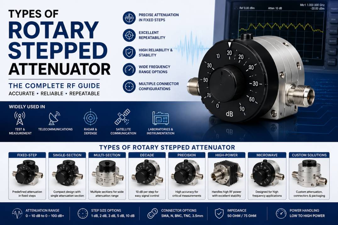
A rotary stepped attenuator is a passive RF and microwave component used to reduce signal power by a precisely controlled amount. Unlike a continuously variable attenuator, which provides a smooth range of attenuation, a rotary stepped attenuator uses a rotary control to select predefined attenuation values.
Rotary stepped attenuators are widely used in RF test equipment, communication systems, laboratory instruments, signal generators, spectrum analyzers, wireless infrastructure, radar systems, and electronic testing applications.
Depending on the design, a rotary stepped attenuator may provide attenuation steps such as 1 dB, 2 dB, 3 dB, 5 dB, 10 dB, or combinations of these values. Multiple sections can be combined to provide a larger overall attenuation range while maintaining good impedance matching and repeatability.
Understanding the different types of rotary stepped attenuators is important when selecting an RF attenuator for a specific frequency, power level, attenuation range, connector configuration, and measurement requirement.
What Is a Rotary Stepped Attenuator?
A rotary stepped attenuator is a manually controlled RF attenuator that uses a rotary switch or mechanical selector to introduce different levels of attenuation into an RF transmission path.
Each position of the rotary control corresponds to a predefined attenuation value.
For example, a rotary stepped attenuator may provide:
- 0 dB
- 1 dB
- 2 dB
- 3 dB
- 5 dB
- 10 dB
- 20 dB
- 30 dB
- 40 dB
- 50 dB
- 60 dB
The actual attenuation range and step configuration depend on the attenuator design.
A typical RF rotary stepped attenuator contains precision resistive networks, RF switching contacts, mechanical switching components, connectors, and a housing designed to maintain electromagnetic shielding.
How Does a Rotary Stepped Attenuator Work?
The basic purpose of an attenuator is to reduce RF signal amplitude while maintaining a controlled impedance, commonly 50 ohms in RF and microwave systems.
When the rotary selector is moved, a different resistive attenuation network is connected into the RF signal path.
The selected network absorbs or dissipates a portion of the RF power, reducing the output signal by the specified attenuation value.
For example, if a signal generator produces:
0 dBm
and a 20 dB rotary stepped attenuator is selected, the ideal output becomes:
-20 dBm
The actual output may differ slightly because of insertion loss, frequency response, impedance mismatch, and attenuation accuracy.
Main Types of Rotary Stepped Attenuators
Rotary stepped attenuators can be categorized according to their attenuation step, circuit configuration, attenuation range, frequency range, power capability, construction, and application.
The major types include:
- Fixed-Step Rotary Attenuator
- Single-Section Rotary Stepped Attenuator
- Multi-Section Rotary Stepped Attenuator
- Decade Rotary Stepped Attenuator
- Binary Rotary Stepped Attenuator
- Precision Rotary Stepped Attenuator
- High-Power Rotary Stepped Attenuator
- Low-Power Measurement Attenuator
- Coaxial Rotary Stepped Attenuator
- Microwave Rotary Stepped Attenuator
- Multi-Port Rotary Attenuator
- Custom Rotary Stepped Attenuator
1. Fixed-Step Rotary Attenuator
A fixed-step rotary attenuator provides a predefined set of attenuation levels.
The user rotates the control to select the required attenuation.
Common step values include:
- 1 dB
- 2 dB
- 3 dB
- 5 dB
- 6 dB
- 10 dB
- 20 dB
Applications
Fixed-step rotary attenuators are commonly used in:
- RF laboratories
- Signal testing
- Communication equipment
- Calibration systems
- Antenna testing
- Receiver testing
Advantages
- Simple operation
- Repeatable attenuation
- Mechanical reliability
- Easy visual indication
- No external power required
2. Single-Section Rotary Stepped Attenuator
A single-section rotary stepped attenuator uses one rotary switching mechanism to select different attenuation states.
These attenuators are generally compact and are useful where the required attenuation range is relatively limited.
Typical Characteristics
- Compact construction
- Simple rotary control
- Limited number of attenuation positions
- Low insertion complexity
- Suitable for laboratory and equipment integration
Single-section designs are often selected when space and simplicity are more important than achieving a very large attenuation range.
3. Multi-Section Rotary Stepped Attenuator
A multi-section rotary stepped attenuator combines multiple attenuation networks to achieve a wider attenuation range and finer control.
For example, separate sections may provide coarse and fine attenuation.
A configuration could use:
- 0–10 dB fine section
- 0–20 dB medium section
- 0–50 dB coarse section
The combination provides greater flexibility than a single attenuation section.
Benefits
- Wide attenuation range
- Fine attenuation adjustment
- Better control over signal level
- Suitable for RF measurement systems
4. Decade Rotary Stepped Attenuator
A decade attenuator uses a structured sequence of attenuation values to provide convenient signal-level adjustment.
A common arrangement may use a 10 dB section together with smaller increments.
For example:
0–90 dB in 10 dB increments
or a combination of coarse and fine sections.
Decade-style attenuators are especially useful in test instruments because operators can quickly select a known attenuation value.
Applications
- RF signal generators
- Receiver testing
- Laboratory test benches
- Calibration equipment
- Communication testing
5. Binary Rotary Stepped Attenuator
Binary attenuation architectures use sections based on weighted attenuation values.
For example, sections could theoretically represent:
- 1 dB
- 2 dB
- 4 dB
- 8 dB
- 16 dB
- 32 dB
Although binary architectures are particularly common in electronically controlled attenuators, similar weighted attenuation concepts can be used in switched attenuator assemblies.
Advantages
- Large number of possible attenuation states
- Efficient control architecture
- Fine resolution
- Suitable for automated RF systems
6. Precision Rotary Stepped Attenuator
A precision rotary stepped attenuator is designed for applications where attenuation accuracy, repeatability, impedance matching, and low VSWR are particularly important.
These attenuators are commonly used in:
- RF calibration
- Test and measurement
- Laboratory instrumentation
- Network analyzer testing
- Receiver characterization
- Signal generator calibration
Important Specifications
Precision rotary attenuators may specify:
- Attenuation accuracy
- Frequency response
- Return loss
- VSWR
- Insertion loss
- Switching repeatability
- Power handling
- Connector type
Precision construction helps maintain predictable RF performance across repeated switching operations.
7. High-Power Rotary Stepped Attenuator
High-power rotary stepped attenuators are designed to handle significantly higher RF power than standard laboratory attenuators.
The resistive elements and internal construction must dissipate heat safely.
Design Considerations
High-power rotary attenuators may incorporate:
- High-power resistive elements
- Thermal management
- Larger internal structures
- Heat-resistant materials
- Improved mechanical contacts
- Heavy-duty connectors
Applications
- RF transmitters
- Power amplifier testing
- Broadcast systems
- Radar testing
- Base-station testing
- RF power measurement
Power handling is frequency-dependent, so the manufacturer’s rated power should always be considered at the actual operating frequency and duty cycle.
8. Low-Power Measurement Rotary Attenuator
Low-power rotary attenuators are primarily designed for signal-level measurement and laboratory applications.
They are commonly used with:
- Signal generators
- Spectrum analyzers
- Oscilloscopes with RF inputs
- Vector network analyzers
- RF receivers
- Test fixtures
The objective is generally to provide accurate, repeatable attenuation rather than high power dissipation.
9. Coaxial Rotary Stepped Attenuator
A coaxial rotary stepped attenuator uses coaxial RF transmission paths and is commonly designed around a controlled impedance, such as 50 ohms.
Common coaxial connector options include:
- SMA
- N-Type
- BNC
- TNC
- 7/16 DIN
- 3.5 mm
- 2.92 mm
Connector selection depends on frequency, power, mechanical requirements, and application.
Applications
Coaxial rotary attenuators are widely used in:
- RF laboratories
- Telecom testing
- Antenna systems
- Wireless communication
- RF production testing
- Instrumentation
10. Microwave Rotary Stepped Attenuator
Microwave rotary stepped attenuators are designed for higher-frequency applications where mechanical construction, connector quality, internal geometry, and transmission-line characteristics become increasingly important.
They may be used at frequencies extending into the microwave region depending on the specific design.
Applications
- Radar
- Satellite communication
- Microwave testing
- Aerospace systems
- RF component characterization
- High-frequency research
At higher frequencies, small mechanical changes can significantly influence insertion loss, VSWR, phase response, and attenuation accuracy.
11. Multi-Port Rotary Attenuator
Some specialized rotary attenuator architectures provide multiple RF ports or switching paths.
These designs can combine attenuation selection with RF routing functions.
Applications
- RF switching systems
- Test automation
- Laboratory equipment
- Communication test systems
- Multi-channel RF instrumentation
Multi-port configurations are useful when several signal paths need controlled attenuation within one assembly.
12. Custom Rotary Stepped Attenuator
Custom rotary stepped attenuators are designed according to specific electrical and mechanical requirements.
Customization can include:
- Frequency range
- Attenuation range
- Step size
- Power handling
- Connector type
- Mounting configuration
- Rotary switch style
- Housing dimensions
- Environmental requirements
- Calibration requirements
Custom RF attenuators are particularly useful when standard commercial products do not meet the required combination of frequency, attenuation, power, size, and connector specifications.
Rotary Stepped Attenuator Based on Step Size
One of the simplest ways to classify rotary attenuators is by attenuation step.
1 dB Step Attenuator
A 1 dB step provides very fine control over RF signal level.
It is useful for:
- Precision measurements
- Receiver testing
- Calibration
- Signal optimization
2 dB Step Attenuator
A 2 dB configuration provides moderate resolution while maintaining a practical attenuation range.
3 dB Step Attenuator
A 3 dB step is useful when signal power needs to be adjusted in relatively noticeable increments.
5 dB Step Attenuator
A 5 dB step provides a convenient balance between adjustment resolution and attenuation range.
10 dB Step Attenuator
10 dB steps are commonly used for coarse RF signal-level adjustment.
They are especially useful when a large attenuation range needs to be covered with fewer switching positions.
Rotary Stepped Attenuator Circuit Configurations
The internal attenuation network can use different resistive topologies.
Common RF attenuator configurations include:
Pi Attenuator
A Pi attenuator uses a resistor arrangement resembling the Greek letter Pi.
It is widely used in impedance-controlled RF circuits.
T Attenuator
A T attenuator uses a resistor network arranged in a T configuration.
Both Pi and T networks can be designed to provide a specified attenuation while maintaining the desired characteristic impedance.
Bridged-T Attenuator
A bridged-T configuration can provide useful attenuation characteristics and is used in certain precision and switched attenuator designs.
The appropriate topology depends on frequency range, power requirements, impedance, attenuation value, and mechanical implementation.
Important Specifications of Rotary Stepped Attenuators
When selecting a rotary stepped attenuator, several specifications should be evaluated.
Frequency Range
Frequency range indicates the RF frequencies over which the attenuator is designed to operate.
Examples may include:
- DC to 1 GHz
- DC to 3 GHz
- DC to 6 GHz
- DC to 18 GHz
- DC to 26.5 GHz
- Higher microwave frequencies
The actual operating range depends on the product design.
Attenuation Range
Attenuation range defines the minimum and maximum attenuation available.
For example:
0–10 dB
0–30 dB
0–60 dB
0–100 dB
A wider range provides greater signal-level control.
Attenuation Step
Step size defines the smallest change that can be selected.
A 1 dB step provides finer control than a 10 dB step.
Impedance
RF systems commonly use:
50 ohms
Some broadcast and video systems use:
75 ohms
The attenuator impedance should match the system to minimize reflections.
VSWR
VSWR measures the degree of impedance mismatch between the attenuator and connected RF system.
Low VSWR is generally desirable, especially in precision RF measurement systems.
Insertion Loss
Insertion loss is the loss introduced by the attenuator or signal path when operating in its minimum attenuation state.
Low insertion loss is important when the attenuator is used as part of a sensitive RF measurement chain.
Attenuation Accuracy
Attenuation accuracy indicates how closely the actual attenuation matches the specified value.
For precision measurement, low attenuation error is particularly important.
Return Loss
Return loss indicates how effectively the RF device is matched to the transmission system.
Higher return loss generally indicates better impedance matching.
Power Handling
Power rating defines how much RF power the attenuator can safely handle under specified conditions.
Power ratings may differ depending on:
- Frequency
- Temperature
- Duty cycle
- Attenuation setting
- Ambient conditions
Rotary Stepped Attenuator vs Variable Attenuator
Although both devices control RF signal level, they operate differently.
| Feature | Rotary Stepped Attenuator | Variable Attenuator |
|---|---|---|
| Control | Discrete steps | Continuous or adjustable |
| Attenuation | Predefined values | Variable range |
| Repeatability | Excellent | Depends on design |
| Adjustment | Rotary positions | Knob or electronic control |
| Typical Use | Precision testing | Signal adjustment |
| Calibration | Easier at defined steps | More complex |
| Control Resolution | Defined by step size | Continuously adjustable |
A rotary stepped attenuator is preferred when repeatable and clearly defined attenuation values are required.
Rotary Stepped Attenuator vs Fixed Attenuator
A fixed attenuator provides one permanent attenuation value.
A rotary stepped attenuator provides multiple selectable attenuation values in one device.
For example, a fixed attenuator may provide only:
10 dB
while a rotary stepped attenuator may provide:
0, 1, 2, 3, 5, 10, 20, 30 dB
The rotary design provides greater flexibility for testing and system adjustment.
Applications of Rotary Stepped Attenuators
Rotary stepped attenuators are used across many RF and microwave industries.
RF Test and Measurement
They are used to control signal levels during component testing and system characterization.
Telecommunications
Telecom engineers use attenuators to simulate transmission loss, evaluate receiver sensitivity, and test RF links.
Wireless Networks
Rotary attenuators can be used during testing of:
- Cellular equipment
- Wi-Fi systems
- Private wireless networks
- Base stations
- RF modules
Radar Systems
Radar test systems use controlled attenuation to simulate different signal levels and evaluate receiver performance.
Satellite Communication
Attenuators can be used to control RF signal levels during satellite communication equipment testing and link simulation.
Aerospace and Defense
Precision RF attenuators are useful in RF test benches, communication equipment, radar testing, electronic warfare test environments, and microwave instrumentation.
RF Laboratories
Laboratories use rotary attenuators for repeatable signal-level control during RF experiments.
Production Testing
Manufacturing facilities can use attenuators to verify RF equipment performance during production and quality-control testing.
Benefits of Rotary Stepped Attenuators
Rotary stepped attenuators provide several important benefits.
Precise Signal Control
Users can select a known attenuation value quickly.
Excellent Repeatability
Defined switching positions make repeated measurements easier.
Passive Operation
Many rotary stepped attenuators operate without external electrical power.
Easy Manual Operation
A mechanical rotary selector provides straightforward operation.
Wide Attenuation Options
Multiple sections can provide a broad attenuation range.
Good RF Performance
Precision designs can provide controlled impedance, low VSWR, and predictable attenuation.
Durable Construction
Mechanical rotary switching can provide long service life when properly engineered.
Factors Affecting Rotary Attenuator Performance
Several factors can influence the actual performance of a rotary stepped attenuator.
Frequency
Attenuation accuracy and VSWR can change with frequency.
Connector Quality
Poor-quality connectors can increase insertion loss and reflection.
Cable Configuration
The connected RF cable can influence the overall measurement.
Temperature
Resistance values and mechanical dimensions can change with temperature.
Power Level
High RF power can cause heating and alter attenuator characteristics.
Mechanical Wear
Repeated switching can eventually affect mechanical contacts and RF performance.
How to Select the Right Rotary Stepped Attenuator
Follow these steps when selecting a rotary stepped attenuator.
Step 1: Determine the Frequency Range
Select an attenuator designed for the highest operating frequency in your application.
Step 2: Determine the Required Attenuation
Identify the maximum attenuation required.
Step 3: Select the Step Size
Choose 1 dB, 2 dB, 3 dB, 5 dB, 10 dB, or another step according to the required resolution.
Step 4: Check Power Handling
Ensure the attenuator can handle the maximum RF input power.
Step 5: Check Impedance
Verify whether your system requires 50-ohm or 75-ohm impedance.
Step 6: Check VSWR and Return Loss
For precision RF testing, choose a design with suitable impedance-matching performance.
Step 7: Select the Connector
Match the connector with the existing RF equipment and cable assembly.
Step 8: Consider Environmental Requirements
For field and industrial applications, consider temperature range, humidity, vibration, shock, and enclosure requirements.
Step 9: Evaluate Mechanical Configuration
Check the number of positions, switching mechanism, mounting method, actuator style, and housing dimensions.
Common Applications by Attenuation Range
| Attenuation Range | Typical Application |
|---|---|
| 0–10 dB | Fine signal adjustment |
| 0–20 dB | RF laboratory testing |
| 0–30 dB | Receiver testing |
| 0–60 dB | Communication testing |
| 0–90 dB | Signal simulation |
| 0–100 dB+ | Advanced test systems |
These ranges are examples only; actual product configurations vary by manufacturer and application.
Common Rotary Stepped Attenuator Connectors
SMA
SMA connectors are widely used for compact RF and microwave applications.
N-Type
N-Type connectors are commonly used in outdoor, telecom, antenna, and higher-power RF applications.
BNC
BNC connectors are widely used in laboratory instrumentation and test equipment.
TNC
TNC connectors provide a threaded alternative for applications requiring greater mechanical security.
3.5 mm and 2.92 mm
These connectors are used in higher-frequency microwave and test-and-measurement applications.
Rotary Stepped Attenuators in RF Cable Assemblies
A rotary stepped attenuator is often connected to RF cable assemblies during testing.
The cable assembly must also be selected according to:
- Frequency
- Impedance
- Connector
- Cable loss
- Power rating
- VSWR
- Flexibility
- Environmental conditions
Using a high-performance attenuator with a poor-quality RF cable can reduce the accuracy of the overall measurement system.
Testing Rotary Stepped Attenuators
Several measurements can be performed to verify attenuator performance.
Insertion Loss Test
Measures signal loss through the attenuator.
Attenuation Accuracy Test
Compares actual attenuation against the specified attenuation.
Return Loss Test
Evaluates impedance matching.
VSWR Test
Determines voltage standing wave ratio across the operating frequency range.
Power Handling Test
Evaluates performance under specified RF power conditions.
Frequency Response Test
Determines how attenuation changes across frequency.
Vector network analyzers are commonly used for detailed RF characterization.
Future Trends in Rotary Stepped Attenuators
RF test and measurement requirements are evolving as wireless systems move toward higher frequencies and wider bandwidths.
Important trends include:
- Higher-frequency microwave attenuators
- Improved attenuation accuracy
- Compact mechanical designs
- Higher power handling
- Better connector technologies
- Low-VSWR designs
- Multi-section attenuation systems
- Hybrid mechanical and electronic control
- Automated RF test systems
- High-frequency calibration equipment
The continued development of 5G-Advanced, Wi-Fi 7, satellite communication, radar, aerospace electronics, and advanced RF test systems is increasing demand for accurate signal-level control.
Why Rotary Stepped Attenuators Are Important in RF Testing
RF systems often need to operate across a wide range of signal levels. Testing only at one signal level does not provide enough information about receiver sensitivity, dynamic range, overload performance, or system stability.
A rotary stepped attenuator allows engineers to systematically change signal power and observe how the device under test responds.
For example, an RF receiver can be tested at:
- -20 dBm
- -30 dBm
- -40 dBm
- -50 dBm
- -60 dBm
- -70 dBm
by changing the attenuation between the signal generator and receiver.
This makes rotary stepped attenuators valuable tools for RF characterization and production testing.
Conclusion
Rotary stepped attenuators are essential passive RF components for precise and repeatable signal-level control. They are available in different configurations based on attenuation step, attenuation range, frequency, power handling, circuit topology, connector type, and mechanical construction.
Common types include fixed-step rotary attenuators, multi-section attenuators, decade attenuators, precision attenuators, high-power attenuators, coaxial attenuators, microwave attenuators, and custom rotary stepped attenuators.
When selecting a rotary stepped attenuator, engineers should carefully evaluate frequency range, attenuation range, step size, impedance, VSWR, return loss, insertion loss, attenuation accuracy, power handling, connector type, and environmental requirements.
For demanding RF and microwave applications, the right rotary stepped attenuator can improve measurement repeatability, signal control, and overall test-system accuracy.
Frequently Asked Questions (FAQ)
1. What is a rotary stepped attenuator?
A rotary stepped attenuator is a passive RF device that reduces signal power by selectable, predefined attenuation steps using a rotary control.
2. What are the main types of rotary stepped attenuators?
Major types include fixed-step, single-section, multi-section, decade, binary, precision, high-power, low-power, coaxial, microwave, multi-port, and custom rotary stepped attenuators.
3. What is the difference between a rotary stepped attenuator and a variable attenuator?
A rotary stepped attenuator provides predefined attenuation values, while a variable attenuator allows continuous or more gradual adjustment over an attenuation range.
4. What attenuation steps are available in rotary attenuators?
Common attenuation steps include 1 dB, 2 dB, 3 dB, 5 dB, 6 dB, and 10 dB. Custom step configurations are also available.
5. Are rotary stepped attenuators passive devices?
Yes. Standard mechanical rotary stepped attenuators are passive RF components and normally do not require an external power supply.
6. What impedance is commonly used for RF rotary attenuators?
50 ohms is the most common impedance for RF and microwave rotary attenuators. Some applications, particularly broadcast and video systems, use 75 ohms.
7. Where are rotary stepped attenuators used?
They are used in RF laboratories, telecommunications, radar, satellite communication, wireless testing, signal generators, receiver testing, calibration systems, and production test equipment.
8. What is attenuation accuracy?
Attenuation accuracy indicates how closely the actual attenuation matches the specified attenuation value. High accuracy is particularly important for RF calibration and precision measurement.
9. Why is VSWR important in a rotary stepped attenuator?
VSWR indicates impedance matching. A suitable low-VSWR design helps reduce signal reflections and improves RF measurement accuracy.
10. Can rotary stepped attenuators handle high RF power?
Some are specifically designed for high-power operation. However, power handling depends on frequency, attenuation setting, cooling, duty cycle, and the specific attenuator design.
11. Which connectors are used with rotary stepped attenuators?
Common connectors include SMA, N-Type, BNC, TNC, 3.5 mm, and 2.92 mm. The correct connector depends on frequency and application requirements.
12. How do I choose a rotary stepped attenuator?
Consider the required frequency range, attenuation range, step size, impedance, VSWR, attenuation accuracy, power rating, connector type, environmental conditions, and mechanical configuration.
13. What is a precision rotary stepped attenuator?
A precision rotary stepped attenuator is designed for applications requiring accurate, repeatable attenuation and controlled RF characteristics, particularly in calibration and test-and-measurement systems.
14. What is a high-power rotary stepped attenuator?
A high-power rotary stepped attenuator is designed to dissipate higher levels of RF power while maintaining specified electrical and thermal performance.
15. Can rotary stepped attenuators be customized?
Yes. Custom rotary stepped attenuators can be designed with specific frequency ranges, attenuation values, step sizes, power ratings, connectors, dimensions, mounting configurations, and environmental specifications.










