
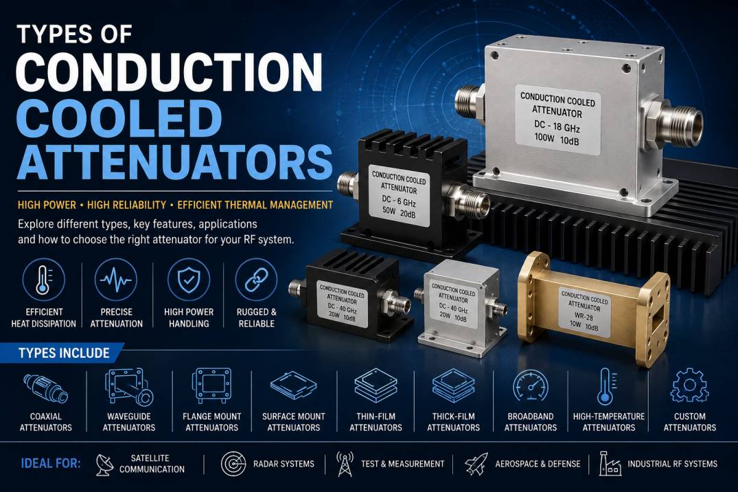
Conduction cooled attenuators are specialized RF and microwave components designed to reduce signal power while transferring the generated heat directly through a conductive thermal path. They are particularly important in high-power and thermally constrained RF systems where conventional air-cooled components may not provide sufficient thermal performance.
An attenuator introduces a controlled amount of insertion loss into an RF signal path. While attenuation reduces signal amplitude, part of the RF power is converted into heat inside the attenuator. In high-power applications, managing this heat is essential for maintaining stable electrical performance and preventing component failure.
Unlike conventional air-cooled attenuators that depend primarily on natural or forced airflow, conduction cooled attenuators transfer heat from the resistive element through the component body, mounting surface, chassis, cold plate, or heatsink.
These attenuators are widely used in aerospace, defense, radar, satellite communication, RF test equipment, electronic warfare, telecommunications, industrial RF systems, and other high-reliability applications.
What Is a Conduction Cooled Attenuator?
A conduction cooled attenuator is an RF component that reduces signal power while dissipating internally generated heat through direct thermal conduction.
The attenuator typically contains precision resistive elements configured to achieve a specified attenuation value and impedance. The resistive network absorbs a portion of the RF energy and converts it into thermal energy.
The heat then travels through a low-thermal-resistance path toward a mounting surface or external cooling structure.
A typical conduction cooled RF attenuator consists of:
- RF input connector
- RF output connector
- Resistive attenuation network
- Conductive body
- Thermal interface or mounting surface
- Heat-spreading structure
- Mechanical mounting features
- RF shielding structure
The exact construction depends on the operating frequency, attenuation value, power rating, package style, and cooling requirements.
Why Are Conduction Cooled Attenuators Important?
RF systems are becoming increasingly compact while operating at higher frequencies and power levels. This creates significant thermal-management challenges.
When an RF attenuator absorbs high levels of power, the absorbed energy becomes heat. If this heat is not removed efficiently, the component temperature can rise and cause:
- Performance degradation
- Increased insertion loss
- Resistance changes
- Connector damage
- Thermal stress
- Reduced reliability
- Permanent component failure
Conduction cooling provides a direct thermal path from the attenuator to the equipment chassis or cooling structure.
This makes conduction cooled attenuators particularly valuable in systems where:
- Airflow is limited
- Fans are undesirable
- Equipment is sealed
- Space is restricted
- Weight must be minimized
- Reliability is critical
- Thermal management is integrated into the equipment structure
How Does a Conduction Cooled Attenuator Work?
The basic operation involves two simultaneous processes: RF attenuation and thermal conduction.
RF Attenuation
The incoming RF signal enters the attenuator through the input port. The internal resistive network absorbs a controlled amount of RF power.
For example, a 10 dB attenuator reduces the output power to approximately one-tenth of the input power in linear power terms, assuming an ideal matched system.
The remaining RF energy exits through the output port.
Heat Generation
The RF power absorbed by the resistive network is converted into heat.
For a high-power attenuator, this can represent a substantial thermal load.
Heat Conduction
The generated heat travels through the conductive internal structure toward the external mounting surface.
The equipment chassis, cold plate, heatsink, or thermal interface then removes the heat.
This creates a complete thermal path:
RF Energy → Resistive Element → Conductive Body → Mounting Surface → Cooling Structure
Major Types of Conduction Cooled Attenuators
Conduction cooled attenuators can be categorized in several ways, including attenuation value, power handling, frequency range, mechanical construction, RF technology, and mounting configuration.
The major types include:
- Fixed Conduction Cooled Attenuators
- High-Power Conduction Cooled Attenuators
- Surface-Mount Conduction Cooled Attenuators
- Flange-Mount Conduction Cooled Attenuators
- Coaxial Conduction Cooled Attenuators
- Waveguide Conduction Cooled Attenuators
- Thin-Film Conduction Cooled Attenuators
- Thick-Film Conduction Cooled Attenuators
- Broadband Conduction Cooled Attenuators
- High-Frequency Microwave Conduction Cooled Attenuators
- High-Temperature Conduction Cooled Attenuators
- Custom Conduction Cooled Attenuators
1. Fixed Conduction Cooled Attenuators
Fixed conduction cooled attenuators provide a predetermined attenuation value.
Common attenuation values include:
- 1 dB
- 2 dB
- 3 dB
- 5 dB
- 6 dB
- 10 dB
- 15 dB
- 20 dB
- 30 dB
- 40 dB
The attenuation value remains essentially fixed during normal operation.
Applications
Fixed conduction cooled attenuators are used in:
- RF transmitters
- Radar systems
- Satellite equipment
- RF amplifiers
- Test equipment
- Electronic warfare systems
- Communication systems
Advantages
- Simple construction
- Stable attenuation
- High reliability
- Excellent repeatability
- Suitable for high-power RF systems
2. High-Power Conduction Cooled Attenuators
High-power conduction cooled attenuators are designed to absorb significant RF power while maintaining an acceptable operating temperature.
They use thermally efficient materials and construction techniques to move heat away from the internal resistive element.
Power ratings may range from relatively low levels to hundreds of watts or more depending on frequency, duty cycle, mounting conditions, pulse characteristics, and thermal design.
Important Specifications
When selecting a high-power conduction cooled attenuator, consider:
- Average power
- Peak power
- Pulse power
- Duty cycle
- Operating frequency
- Case temperature
- Mounting temperature
- Thermal resistance
- VSWR
- Insertion loss
- Attenuation accuracy
3. Surface-Mount Conduction Cooled Attenuators
Surface-mount conduction cooled attenuators are designed to transfer heat directly into a PCB, chassis, metal carrier, or thermal spreader.
They are useful when compact dimensions and direct thermal integration are required.
Applications
- Aerospace electronics
- Defense electronics
- RF modules
- Compact transmitters
- Microwave circuits
- Phased-array systems
- Satellite payload electronics
Advantages
- Compact footprint
- Direct thermal path
- Low profile
- Easy integration into RF modules
- Reduced reliance on airflow
4. Flange-Mount Conduction Cooled Attenuators
Flange-mounted attenuators incorporate a mechanical flange or mounting surface that provides both physical attachment and thermal conduction.
The flange is typically attached to a thermally conductive chassis or cold plate.
Benefits
- Secure mechanical mounting
- Efficient heat transfer
- Repeatable installation
- Suitable for high-power systems
- Easy integration into equipment structures
These attenuators are particularly useful in rugged aerospace and defense systems.
5. Coaxial Conduction Cooled Attenuators
Coaxial conduction cooled attenuators use coaxial RF transmission structures to carry the RF signal between the input and output ports.
They are commonly available with connectors such as:
- SMA
- N-Type
- TNC
- 2.92 mm
- 2.4 mm
- 1.85 mm
- Other specialized microwave connectors
The external body or mounting structure provides the thermal path.
Applications
- RF test equipment
- Microwave systems
- Communications equipment
- Radar
- RF amplifiers
- Laboratory instrumentation
6. Waveguide Conduction Cooled Attenuators
Waveguide conduction cooled attenuators are designed for microwave and millimeter-wave systems that use waveguide transmission.
Instead of coaxial connectors, they incorporate waveguide interfaces.
Applications
- Radar systems
- Satellite communication
- Microwave backhaul
- Aerospace systems
- Electronic warfare
- High-frequency instrumentation
Waveguide attenuators are selected according to the waveguide band and mechanical interface.
7. Thin-Film Conduction Cooled Attenuators
Thin-film technology uses precisely deposited resistive materials to create controlled RF resistance values.
Thin-film attenuators can provide excellent electrical consistency and are suitable for applications where tight RF performance is required.
Characteristics
- Precise resistance values
- Compact construction
- Good high-frequency performance
- Repeatable electrical characteristics
- Suitable for microwave applications
Thin-film designs are frequently considered when dimensional precision and RF consistency are important.
8. Thick-Film Conduction Cooled Attenuators
Thick-film attenuators use relatively thicker resistive materials deposited onto a suitable substrate.
They can provide good power-handling capabilities while maintaining practical manufacturing costs.
Applications
- RF power circuits
- Microwave modules
- Industrial electronics
- Communications systems
- Defense electronics
The appropriate technology depends on the required frequency, power, thermal resistance, accuracy, and physical construction.
9. Broadband Conduction Cooled Attenuators
Broadband conduction cooled attenuators are designed to operate over a wide range of frequencies.
A broadband attenuator must maintain acceptable:
- Attenuation accuracy
- Return loss
- VSWR
- Insertion loss
- Power handling
across its specified frequency range.
Applications
- Test and measurement
- Broadband amplifiers
- RF laboratories
- Communication systems
- Signal conditioning
- Electronic warfare equipment
10. High-Frequency Microwave Conduction Cooled Attenuators
High-frequency conduction cooled attenuators are designed for microwave and millimeter-wave applications.
At higher frequencies, mechanical dimensions, connector geometry, material properties, parasitic effects, and manufacturing tolerances become increasingly important.
These attenuators may be used in frequency ranges extending into tens of gigahertz depending on the design.
Applications
- 5G and advanced wireless systems
- Radar
- Satellite communication
- Aerospace electronics
- Microwave test equipment
- Millimeter-wave research
- Electronic warfare
11. High-Temperature Conduction Cooled Attenuators
High-temperature conduction cooled attenuators are designed to operate reliably in environments where the equipment temperature is elevated.
The design must consider:
- Material stability
- Thermal expansion
- Resistive element temperature coefficient
- Connector performance
- Mechanical stress
- Maximum operating temperature
These attenuators are useful in aerospace, defense, industrial, and high-temperature RF applications.
12. Custom Conduction Cooled Attenuators
Custom conduction cooled attenuators are developed according to application-specific electrical and mechanical requirements.
A custom design may specify:
- Frequency range
- Attenuation value
- Power rating
- Connector configuration
- Mounting interface
- Body dimensions
- Thermal resistance
- Operating temperature
- Environmental requirements
- VSWR
- Return loss
- Pulse power
- Duty cycle
Custom attenuators are useful when standard catalog components cannot satisfy the system requirements.
Conduction Cooled Attenuators by Attenuation Value
Another useful way to classify attenuators is according to attenuation level.
Low Attenuation
Typical values include 1 dB, 2 dB, and 3 dB.
These are commonly used for:
- Fine signal adjustment
- Impedance matching
- Power balancing
- RF level control
Medium Attenuation
Typical values include 5 dB, 6 dB, 10 dB, and 15 dB.
Applications include:
- RF signal conditioning
- Amplifier testing
- Transmitter protection
- Receiver input control
High Attenuation
Typical values may include 20 dB, 30 dB, and 40 dB or higher.
These are useful for:
- Strong signal reduction
- Transmitter testing
- RF isolation
- Laboratory measurements
- Signal simulation
Conduction Cooling vs Air Cooling
| Feature | Conduction Cooling | Air Cooling |
|---|---|---|
| Primary heat path | Solid thermal path | Airflow |
| Fan required | Usually no | May be required |
| Sealed equipment | Excellent | More difficult |
| Mechanical integration | High | Moderate |
| Noise | Very low | Fans can produce noise |
| Maintenance | Low | Fans may require maintenance |
| Compact systems | Excellent | Depends on airflow |
| Aerospace applications | Highly suitable | Application dependent |
| Thermal interface | Chassis/cold plate | Air/heatsink |
Conduction Cooling vs Conventional RF Attenuators
A conventional low-power attenuator may be designed primarily around RF performance, physical size, and cost.
A conduction cooled attenuator must consider both RF and thermal performance.
Key additional design factors include:
- Thermal resistance
- Case temperature
- Mounting temperature
- Heat-spreading capability
- Interface material
- Chassis conductivity
- Duty cycle
- Power dissipation
Therefore, a conduction cooled attenuator should be evaluated as part of the complete thermal system.
Key Specifications of Conduction Cooled Attenuators
When selecting an attenuator, several electrical and mechanical parameters should be evaluated.
Frequency Range
The operating frequency determines the RF design, connector choice, materials, and attenuation accuracy.
Attenuation
Attenuation is specified in dB and determines how much the signal is reduced.
Power Rating
Power rating indicates how much RF power the attenuator can dissipate under specified conditions.
Always distinguish between:
- Continuous-wave power
- Average power
- Peak power
- Pulse power
VSWR
VSWR indicates impedance matching performance. Lower VSWR generally means better matching.
Return Loss
Return loss measures reflected RF power relative to incident power.
Higher return loss generally indicates better impedance matching.
Insertion Loss
Insertion loss describes the reduction in signal level introduced by the component beyond its intended attenuation characteristics.
Thermal Resistance
Thermal resistance indicates how effectively heat can move from the resistive element or case to the cooling structure.
Lower thermal resistance generally provides better thermal performance.
Operating Temperature
The operating temperature range defines the environmental conditions under which the attenuator is specified to function.
Connector Type
Connector selection depends on frequency, power level, mechanical requirements, and system architecture.
Thermal Management in Conduction Cooled Attenuators
Thermal design is one of the most important aspects of a conduction cooled attenuator.
Suppose an attenuator receives 100 W of RF power and has a 10 dB attenuation value.
For an ideal matched attenuator, approximately 90% of the input power is absorbed by the attenuator and approximately 10% reaches the output.
That means approximately 90 W becomes heat that must be removed from the component.
This demonstrates why thermal management becomes critical as RF power increases.
Thermal Interface Materials
The thermal path between the attenuator and chassis may involve:
- Direct metal-to-metal mounting
- Thermal grease
- Thermal pads
- Thermal interface films
- Conductive mounting compounds
The selected interface should minimize thermal resistance while maintaining mechanical reliability.
Materials Used in Conduction Cooled Attenuators
Common materials may include:
- Aluminum
- Copper
- Copper alloys
- Brass
- Ceramic substrates
- High-temperature resistive materials
- Specialized RF laminates
Material selection depends on:
- Thermal conductivity
- Electrical conductivity
- Weight
- Coefficient of thermal expansion
- Corrosion resistance
- Mechanical strength
- Operating temperature
Applications of Conduction Cooled Attenuators
Aerospace
Aerospace systems have strict requirements for size, weight, reliability, and thermal management. Conduction cooling is particularly valuable where airflow is restricted.
Defense
Defense RF systems frequently operate in rugged environments and may require compact high-power components.
Applications include:
- Radar
- Electronic warfare
- Tactical communications
- RF countermeasure systems
- Avionics
Satellite Communication
Satellite electronics often require efficient thermal management because cooling resources are limited.
Conduction cooled attenuators can transfer heat directly into spacecraft thermal structures.
Radar Systems
Radar transmitters and receivers can generate substantial RF power and heat.
Attenuators are used for:
- Signal conditioning
- Receiver protection
- Calibration
- Power measurement
- RF testing
RF Test and Measurement
Test equipment uses attenuators to control signal levels and protect sensitive measurement instruments.
Conduction cooled versions are useful when high RF power must be dissipated within compact equipment.
Telecommunications
High-power RF communication equipment can use conduction cooled attenuators for signal conditioning, testing, and RF subsystem protection.
Electronic Warfare
Electronic warfare systems require high-performance RF components capable of operating across demanding frequency and power conditions.
Advantages of Conduction Cooled Attenuators
Conduction cooled attenuators provide several important advantages.
Efficient Thermal Management
Heat is transferred directly to the equipment’s thermal structure.
Fanless Operation
Because cooling can be achieved through conduction, external airflow may not be necessary.
Compact Design
They can be integrated into compact RF modules and chassis.
High Reliability
Reducing dependence on mechanical cooling systems can improve system reliability.
Suitable for Sealed Equipment
Conduction cooling is well suited to sealed electronic systems where air circulation is limited.
Aerospace Compatibility
Their low-profile and chassis-integrated construction can be advantageous in aerospace systems.
Limitations of Conduction Cooled Attenuators
Despite their benefits, conduction cooled attenuators also have limitations.
Dependence on Mounting
Thermal performance depends heavily on the quality of the mechanical and thermal connection to the chassis.
Installation Sensitivity
Poor mounting can increase thermal resistance.
Higher Design Complexity
Thermal and RF requirements must be considered simultaneously.
Higher Cost
Specialized high-power and high-frequency construction can cost more than basic RF attenuators.
Thermal System Dependency
The attenuator cannot be evaluated independently from the chassis or cooling structure in high-power applications.
How to Select a Conduction Cooled Attenuator
The selection process should begin with the electrical requirements and then incorporate thermal and mechanical constraints.
1. Determine the Frequency Range
Identify the minimum and maximum operating frequencies.
2. Determine Attenuation
Select the required attenuation value in dB.
3. Calculate RF Power Dissipation
Determine how much input power will be absorbed and converted into heat.
4. Check Duty Cycle
For pulsed RF systems, average and peak power must both be considered.
5. Evaluate Thermal Resistance
Verify that the attenuator and cooling structure can maintain acceptable temperatures.
6. Select the Connector
Choose an appropriate RF connector according to frequency and power requirements.
7. Check VSWR and Return Loss
Ensure the component meets the required RF matching specifications.
8. Verify Mounting Requirements
Confirm that the attenuator can be mechanically integrated with the chassis, cold plate, or thermal spreader.
9. Check Environmental Requirements
Consider:
- Temperature
- Vibration
- Shock
- Humidity
- Altitude
- Corrosion
- Vacuum
- Outdoor exposure
10. Consider Customization
If standard specifications are insufficient, consider a custom conduction cooled attenuator design.
Common Mistakes When Selecting Conduction Cooled Attenuators
Ignoring Thermal Mounting Conditions
A power rating is meaningful only under its specified thermal conditions.
Looking Only at Peak Power
Peak power may be significantly different from continuous or average power.
Ignoring Duty Cycle
A pulsed system may have a high peak power but a lower average thermal load.
Selecting the Wrong Frequency Range
The attenuator should provide the required RF performance across the complete operating band.
Using an Inadequate Thermal Interface
Poor thermal contact can dramatically increase component temperature.
Ignoring Connector Power Handling
The connector and RF interface must also withstand the required power and frequency.
Conduction Cooled Attenuators for High-Frequency RF Systems
At microwave and millimeter-wave frequencies, small mechanical features can influence RF performance.
Important considerations include:
- Connector geometry
- Internal transmission-line dimensions
- Dielectric properties
- Surface finish
- Manufacturing tolerance
- RF shielding
- Parasitic capacitance
- Parasitic inductance
For high-frequency systems, the mechanical and electrical design must be developed together.
Conduction Cooled Attenuators for Pulse Applications
Many radar and defense systems operate with pulsed RF signals.
For these systems, selecting an attenuator based only on continuous-wave power can be misleading.
Important parameters include:
- Peak pulse power
- Pulse width
- Pulse repetition frequency
- Duty cycle
- Average power
- Thermal recovery time
The attenuator should be evaluated according to the complete pulse profile.
Future Trends in Conduction Cooled Attenuator Technology
The demand for advanced conduction cooled attenuators is increasing as RF systems become smaller, more powerful, and more thermally constrained.
Important trends include:
- Higher RF power density
- Smaller package sizes
- Improved thermal conductivity
- Higher-frequency operation
- Millimeter-wave applications
- Advanced ceramic substrates
- Improved thin-film technology
- Integrated thermal interfaces
- Aerospace-grade packaging
- Custom RF thermal solutions
Future RF systems will increasingly require attenuators that provide both high electrical performance and efficient thermal management within compact packages.
Conclusion
Conduction cooled attenuators are essential RF components for systems where signal attenuation and thermal management must be addressed simultaneously. Unlike conventional air-cooled attenuators, these components transfer heat through a conductive path into a chassis, cold plate, heatsink, or other thermal structure.
The major types include fixed, high-power, surface-mount, flange-mount, coaxial, waveguide, thin-film, thick-film, broadband, high-frequency, high-temperature, and custom conduction cooled attenuators.
Selecting the right conduction cooled attenuator requires careful evaluation of frequency, attenuation, power rating, pulse characteristics, VSWR, return loss, thermal resistance, operating temperature, connector type, and mounting conditions.
For aerospace, defense, radar, satellite communication, electronic warfare, telecommunications, and RF test systems, conduction cooled attenuators can provide an effective combination of RF signal control, compact packaging, and reliable thermal management.
Frequently Asked Questions
1. What is a conduction cooled attenuator?
A conduction cooled attenuator is an RF component that reduces signal power while transferring the heat generated by RF absorption through a conductive path to a chassis, cold plate, heatsink, or other cooling structure.
2. What are the main types of conduction cooled attenuators?
Major types include fixed, high-power, surface-mount, flange-mount, coaxial, waveguide, thin-film, thick-film, broadband, high-frequency, high-temperature, and custom conduction cooled attenuators.
3. Why are conduction cooled attenuators used in high-power RF systems?
High-power RF attenuators convert a significant portion of RF energy into heat. Conduction cooling provides an efficient path for transferring this heat away from the resistive element.
4. What is the difference between conduction cooling and air cooling?
Conduction cooling transfers heat through a solid thermal path, while air cooling relies on natural or forced airflow to remove heat.
5. What is a fixed conduction cooled attenuator?
A fixed conduction cooled attenuator provides a predetermined attenuation value, such as 3 dB, 6 dB, 10 dB, or 20 dB, while using a conductive thermal path to dissipate absorbed RF power.
6. Can conduction cooled attenuators be used for radar?
Yes. They can be used in radar systems for signal conditioning, receiver protection, calibration, testing, and RF power management, provided their frequency and power specifications meet the system requirements.
7. What is thermal resistance in a conduction cooled attenuator?
Thermal resistance describes how effectively heat moves from the attenuator’s heat-generating region to its cooling interface. Lower thermal resistance generally indicates a more effective thermal path.
8. What factors determine the power rating of a conduction cooled attenuator?
Power rating depends on factors including frequency, attenuation, thermal resistance, mounting temperature, case temperature, cooling conditions, duty cycle, pulse characteristics, and component construction.
9. Are conduction cooled attenuators suitable for aerospace applications?
Yes. Their compact, fanless, and chassis-integrated thermal design can make them suitable for aerospace electronics, avionics, satellite systems, and other applications where airflow and space are limited.
10. Can conduction cooled attenuators operate at microwave frequencies?
Yes. Specialized conduction cooled attenuators are available for microwave and millimeter-wave applications, with performance depending on the specific frequency range and RF architecture.
11. What connectors are used with conduction cooled attenuators?
Depending on the frequency and application, conduction cooled attenuators can use SMA, N-Type, TNC, 2.92 mm, 2.4 mm, 1.85 mm, waveguide interfaces, or other specialized RF connectors.
12. Are conduction cooled attenuators suitable for pulsed RF?
Yes, but the attenuator must be selected according to peak power, pulse width, pulse repetition frequency, duty cycle, and average power rather than peak power alone.
13. What is the role of a thermal interface in a conduction cooled attenuator?
The thermal interface connects the attenuator’s conductive body to the cooling structure and helps minimize thermal resistance. Proper mounting is critical for achieving the specified power-handling performance.
14. What industries use conduction cooled attenuators?
They are used in aerospace, defense, radar, satellite communications, telecommunications, electronic warfare, RF test and measurement, industrial RF systems, and microwave electronics.
15. How do I choose the right conduction cooled attenuator?
Consider frequency range, attenuation, average and peak power, duty cycle, VSWR, return loss, thermal resistance, operating temperature, connector type, mounting configuration, environmental conditions, and the available cooling structure.










